It has been several weeks since my first blog but in that time I have been on a steep learning curve and very busy.
Most of what I am about to mention I had actually written in a draft blog but I failed to finalise and publish it before the writing of AER 1. To be fair most of what I did draft went into AER 1 so if you’re likely to read AER 1, I wouldn’t bother continuing from this point!
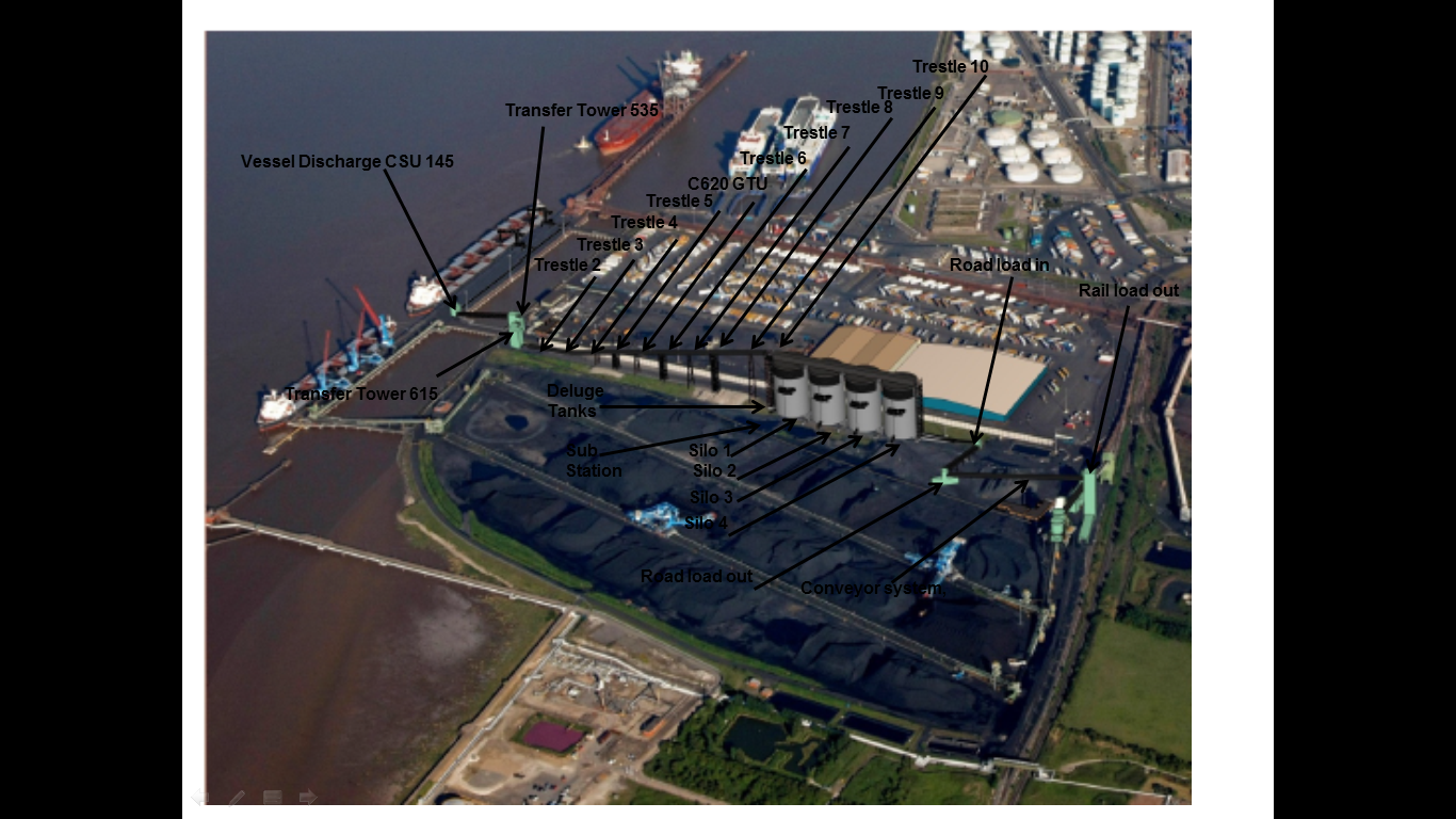
After my first real on site experience with the rail load out silo steel roof I quickly graduated from working as a site engineers assistant to being given a section of work to really get my teeth into. As such I have spent the last 3 weeks piling and resolving the 535, 615, Trestle (T) 2,3,4,5,6,7,8,9,10 and C620 Gravity Take Up Conveyor 620 (GTU C620). It is proving to be a great opportunity as I various issues that has thrown up.
The following picture I prepared for AER 1 and highlights the area of the site I will be working on, effectively Transfer Tower (TT) am now able to work on this element of the project from the ground upwards and see the entire element through from clearance of the site to turning the conveyors on.
The first part of the work has been driving 163 x 27m (13m and 14m sections) 0.27m2 pre-cast RC displacement piles for the foundations of all the previously mentioned elements of the section. To start I was using the GPS equipment to mark out the extremities of the piling area for the plant to break out and prepare a suitable surface. This involves breaking through the 400mm concrete slab that was previously one of the main routes in and out of the complex for the HGVs (hence the thickness), clearing it away, backfilling with a suitable aggregate and compacting. Once the area had been prepared I marked out the exact locations of the piles for the rig to drive them through the next day. I was working 1-2 days ahead of the piling rig to ensure that it was continually piling, trying to minimise the amount of expensive standing time. All Royal Engineer Troop Commander bread and butter stuff up to that stage.
The main issue I had was pile refusal and breakages.
There were 25 breakages, 10 refusals and 2 where the final rake was too large and therefore required replacing. These issues were largely in a couple of the foundation bases.
From the surface it is difficult to establish whether the pile is broken or not and I naturally questioned what the driver was telling me when they started to break one after another. To that end I sat in the cab, with the driver, to see the breakages for myself. The driver was under the impression that the piles were breaking at around 5-8m. Once in the cab it was clear to see that obstructions were being encountered at about 5m due to the number of blows per 0.25m driven length significantly increasing (30-50 where normally 5-20, 5T hammer, 250mm drop) and this would continue through till approx. 8m. This band was where the breaks were suspected to be occurring as the piles were ‘kicking away’ from the driven course. This could be proven when compared to the penetration record of successfully driven piles where an increased stiffness (significantly increased blow count 50 -100) was seen at around 20m+ demonstrating that the toe of the pile had reached the correct depth. If the pile had broken around 5-8m this increased stiffness was not encountered as the upper section would shear off from the lower and simply slide passed it, thus not achieving the correct depth. This was not always the case but as a general rule it indicated a broken pile.
The procedure for a broken pile was initially simple as I would contact the designer with either a recommended location (predicted from the broken pile and 2D off set estimation) or request new co-ordinates. Within a few hours I would receive a confirmed new location to re-plot and drive. At times this new location would drive successfully but not as a general rule. A few of the piles in a couple of the trestle bases required 3 or even 4 replacement positions and the pads were extended in 2 directions to accommodate the new positions. In fact the increased slab dimensions negated the requirement for 6 piles in one location, reducing it to 5, due to the increased capacity of the shallow foundation. On 2 of the pads I decided to stop driving the piles due to the fact that any viable solution was becoming more difficult with the area quickly becoming an underground forest of RC.
The nearest borehole sample I could find was from approx. 100m away and confirmed this obstacle belt of made ground to a depth of 7.4m which included chunks of RC, railway sleepers and large rubber fenders!
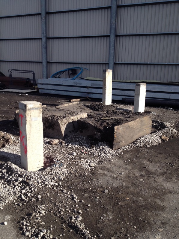
3 x rubber fenders dug out at 3M!
Various solutions were discussed from deep excavations to drilling and eventually the use of steel H-section piles. We managed to ‘find’ a 9.5m 206x206mm steel section to use as probe and drove it right through the middle of the most troublesome base. For my part this was a confidence boosting moment as a number of the management watched the pile being driven (having not been completely content with the number of piles breaking) and it demonstrated behaviour exactly as I had been describing. The number of blows increased at 4m as it entered the obstructions and the pile virtually stopped dead at 6m requiring an increased hammer drop of 850mm to persuade it through the obstruction. This it did and after 8m the number of blows reduced significantly as it had driven through the obstruction and continued normally.
I spent all day Monday consolidating all the paperwork and sending all the info (including the steel results) to the designers for a redesign of 2 of the foundations where a total of 6 piles still require to be driven. I await the outcome and if I have time I will have a bash myself to compare to the actual design that comes back – all good TMR 1 stuff. However things move apace and today we received the RC details for TT535 and 615, so the steel has been ordered and I have been back out marking pile cut off points for crunching and the base ground beam positions for excavation and blinding by the end of the week. As I type this the section manager has just handed me the remaining RC details for the trestle bases – no rest for the wicked.

What was the motivation for selecting prestressed concrete piles if the ground conditions were known to be unfavourable and steel, as you have just demonstrated, would have driven wothout issue? I’m looking for some sort of time, cost, quality thoughts and the ownership of risk. What is the contract form for the ground works how is it packaged, who’s carrying the risk and how is this all being accounted for?
I like this case history…..you’ve put the refusal down to man-made stuff and saved my blushes as I had looked at the lithodgraphy and identified that you were working near some middle Chalk which is fairly famous for chert bands-there are a large number of cases of this buggering-up ground works….The boreholes I have, have a note on one indicating that the drillers had 9 hours chiselling to get through on one….er there’s a bit of a clue!
I wonder…you will no doubt have assessed the driving energy that the H pile could reliably take…?….no? I didn’t think so,although I probably gave you marks for the same problem on Coffer……
I agree with Richard .. the CPR gold is in:
a) the value of S.I.
b) Contractual – if the SI info was passed to the piling company where is the line on unforseen ground conditions and therefore compensation events?
c) when the piling bloke says ‘this is standing time’ when is it and when isn’t it ? they’ll claim standing for every minute they’re not shoving piles in the ground)
d) When a change in design is ordered..does this open the claim floodgates?
…….I TOLD YOU the ground was a risk
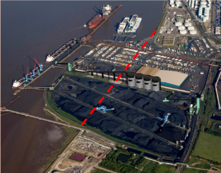
Pre-stressed concrete piles had already been used extensively across the site (400+ per main silo and several hundred elsewhere totalling 2000+) with a refusal/breakage record of about 3%, not really a significant number and hence not deemed a risk for this section. The ground conditions are not unfavourable as such, but there tends to be pockets of resistance probably a specific lorry load of fill for the made ground that cause the problems. In AER 1 I mention briefly that I was told late on that the band of resistance could be due to the approximate location of the old sea defence. I have added the aerial photo at the end of my blog to illustrate the fact that this could be the case as the approximate line of the wall, or at least the dismantled wall, runs through my piling area. I think another argument for the selection of the piles is the fact they are generally better for rapid installation where noise and vibration are not an issue (def not here) and where a granular material is predominately being piled through. The borehole sample in my AER shows predominate SANDS, after the made ground, down to 18.4m and the borehole John sent me bears this out with SANDS and GRAVELS to approx. 20m and stiff CLAYS beyond (where the toe ended up). Larger RC displacement piles are therefore more suited due to the compaction of this coarse grained granular material increasing the bearing capacity and stiffness, this would not be so apparent with the reduced CSA of the steel section. I also think that a steel solution is likely to be significantly more costly due to material cost and the potential requirement for a longer pile (reduced shaft and base capacity/resistance of steel section). However I agree that there is more to this than my simpleton’s answer but I have not had a lot of time to do any in depth analysis of anything yet, as I mentioned things are moving apace and I’ve been flat out again today. I have written about the experience of this episode in AER 1 but I agree that greater analysis is required, answering some of your TCQ, risk, compensation, contractual questions will likely form part of TMR 1 once I start getting my thoughts onto paper.
And of course I assessed the driving energy the H-Section could take – who wouldn’t??.
I asked myself ‘what is the engineering behind the assumption this pile will go in…..what is the risk?’
‘Mr pile operator will you give me 10mins (wishful thinking on my part) to do a fag packet calc on the capacity of this section’
‘Bore off mate, I’ve knocked hundreds of these sections in through much worse’. Calc done.
I have to dash now as we’re digging the TT615 base at the moment for the ground beams and its rather closer to the main HV cables, powering all the jetty infrastructure, than I’m comfortable with!
Big grins all round – a response like that will deal nicely with the technical question at CPR. Follow it with the Risk identification/mitigation contractual bits that John is pointing you towards and you won’t need to answer much more! Great stuff.
Joe
As the other 2 have said – ideal CPR stuff…..and DO input – do not forget them.
Kind Regards