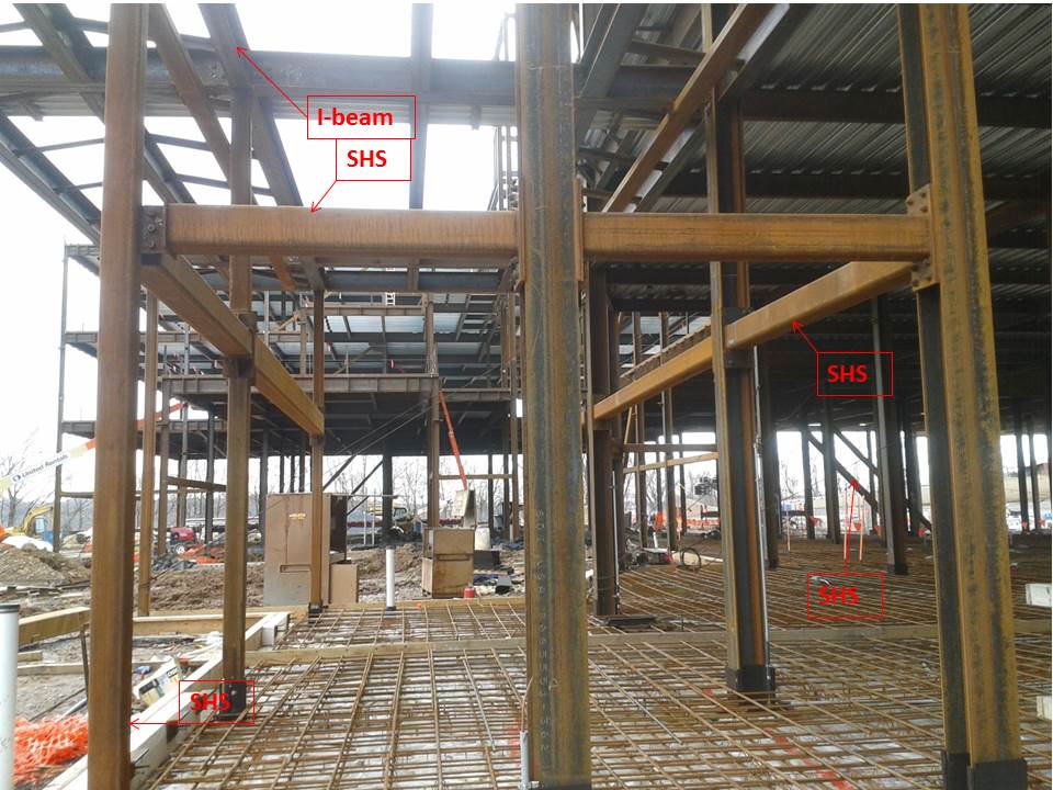
SHS vs I-beams???
Steel buffs unite!….I’m trying to decipher why the structure has used I-beam columns throughout the site and then occasionally SHS columns (generally on the outer columns). In addition, the ground floor horizontal cross bracing uses SHS rather than I-beams. On questioning the contractor – who were not the designers – they could only assume it was for blast protection. Maybe so, but I’m not convinced as it’s also used within the building for diagonal bracing. Thoughts?
With the sudden onset of Spring, the contractors are making hay whilst the sunshines…at least a bit of it anyway. Concreting has commenced once more, although one would have anticipated more being laid in the time available. It would appear that the subcontractor thinks it cheaper to have less manpower and work longer, rather than swarm the site and lay more concrete in one go…once again, we can only speculate, it is the contractors baby to manage as they see fit and from the last schedule review we held with them they guaranteed us they can meet the deadline within 3-days….a big shout! Precast concrete curtains have started to arrive on site and should hopefully start to be put up next week.
I still haven’t got access to the USACE system. They have reworked the application process for ‘foreigners’ and I’ve just found out that I’m the guineapig…the problem is that no one knows what to do with this guineapig when it comes to IT; frustrated to say the least. Nevertheless, I’m trying to make best speed of what I can do without access so am also now undertaking reviews of upcoming construction of two main access control points to the site we are on…encompassing a large amount of environmental, drainage, wetland mitigation as well as interesting security and VBIED mitigations.

The SHS columns look pretty scrawny compared to the I-Beams which look like they are main floor load carrying columns. Maybe they are the sacrificial layer to absorb the pressure wave caused by blast almost like a car crumple zone? That would explain why they are SHS to give them no weaker axis as the threat of loading would be from all outer directions? You should email Mr Portal Frame or the guy with big hands from Nusteel!
I like the conept of a crumple zone for FPE over robustness considerations. I have to confess to being a little saddened that your first port of call for advice wouldn’t have been your old friends in PEW but perhaps that is because you know we’d ask questions leading to answers rather than just give answers.
Howard,
There are frequently peculiar reasons for things like this, not least of which is exposed elements and architectural desire but if it is all to be concealed and definitely a design decision as opposed to buildability option then we’re into structural reasons. You might like to think about this in terms of global stability, the internal forces likely to be carried as a result of potential actions applied, robustness and, I would suggest, end condition and effective length. Angela has quite correctly mentioned equal about both axis and hinted that you might therfore wish to think strut and not beam… I look forward to your thoughts on this.
Richard-I knew you would be reading this and I thought I would get a smile from the others by remembering our guest lecturers! I also decided to think outside of the box for the reasons why they would be used in blast protection. I was looking forwards to it either being shot down as a crazy idea or it actually having something to do with robustness.
So it’s games time?? Just to be clear on the crumple zone concept – these elements are quite short: 1/2 to 1/4 the physical length of other elements and have what appears to be a moment connection at each end. We’re talking a very small effective length and remeber it length squared that counts i.e. they’re something on the very stocky side of the stocky/slender piece which means big numbers for compresion capacity and therefore not a crumple zone (and blast doesn’t work like that, but we’ll cover that on phase 4). Think about the moment connection and look for some global stability…
There’s a whole lotta strange in the picture – none of which I can figure – so I look forward to updates Howard (btw they look like RHS rather than SHS ?)
Firstly Angela – when you’re looking at a structural frame the columns will generally look far less able than the beams – when you design something and see it up for the first time you’ll panic ( look far extreme left – all look usual BAR the ground storey lift – a rule of thumb 152×152 to 2 ; 203×203 to 5 …)
Here everything looks HEAVY. I take it that’s it’s not multi-storey – something above,say 10 floors?
SO here’s a list of weird:
Tube is costly – of itself and particularly connections ( see the flange plate connection front left as a prime example- what would be a simple flange plate for an open section becomes a capping plate plus flange plate for the RHS)
The plated connections in the foreground centre and left look like moment connections ( with 8 bolts they must be) but very unusual into the weak axis of the column ‘H’ sections . I can zoom but can’t makes these out- there must be a cover plate welded between the H flanges.
The plated connections second back right are definitely moment connections into the H from the tube- so I’m starting to think this is some steel robustness core
The end plate second back left ! Has a vertical stiffener on the end plate and is expensive because the bolts will have had to have been flow drilled in to the vertical tube Also the onward tube looks even bigger. This lot looks like they’re expecting Osama’s buddies to turn up in usual combustible garb
Since the main building has simple composite wriggly tin floors already in place I wonder what, if anything is going in here – Often you’d use tube for aesthetics, but not here because, it would have to be fir protected with intumescent paint to remain exposed and this would be an off site process – so these columns are going to disappear…
Finally if tube is being used for bracing it means the bracing loads might be compressive perhaps because they cannot cross cheaper angle or flats – sometimes it is because the architect wants
TY all for your insight …the best I’ve had yet. At the topping off ceremony I managed to corner the structural engrs who designed the building albeit almost 2 years ago. On asking the Q I threw in the tumbleweed…structural engineers parted and suddenly needed to refill their drinks!! Thankfully the senior remained and tried to explain briefly. In short, it certainly is nothing to do with blast prot. She commented that SHS are 40% more expensive than I-beams thus weren’t used frequently; but they were predominantly used on:
+Diagonals – for ease of joint connections.
+External horizontals – because the external precast concrete curtains will be ‘hung’ from these horizontals thus needed to be ‘strong’ in multi-axes.
Obvious when you know how!
Hmm, Bull. I note a horizontal SHS in your pghot with an I beam on the same line above it: Easier to hang from? Lacking adequate strength in one dirtection?? and see John’s comment above about connections – definitely not easier and very definitely not cheaper. So who cocked up the drawings, becasue the client is paying for this…