Archive
Holes and rattlesnakes!
There has been little tangible movement on the flood repair since my last blog other than to’ing and fro’ing of submittals from the contractor for his dewatering plan (or lack of), erosion and sedimentation plan and random others such as concrete and pozzolan specs. It has taking even longer when the chain comprises of the subcontractor, contractor, USACE area office, USACE design office and then additional third parties – state Dept of Transport or State enviro guys – I sit in the middle getting annoyed and cross-eyed. Even with my immature engr eyes I have picked up errors in submittals as simple as not supplying the right concrete ‘psi’ despite it being clearly stated in the specs. Despite the paper-pushing, the clock has started for the contractor; I can only persuade and remind them of the repercussions of late completion but this is preaching to the converted somewhat so the ball is really in their court.
I have continued with the QA on the HQ site. Today was my first soiree into the E&M world…..DALT testing! A quick google search as to what exactly that meant – Duct Air Leakage Testing. Thinking I’d be out of my depth, I was pleased to see that in the initial briefing and explanation for 12 of the witnesses (incl me) that it was quickly apparent that only about 2 of them knew what exactly was going to happen having been baffled by a handout of 20 pages of which 2 pages were only relevant, while the rest all kept quiet trying to look both interested and knowledgeable – the veneer crumbled rapidly when the uniformed guy in the corner with a funny accent started asking questions!!
Adjacent to the office is another USACE project I have been keeping my eye on – a large warehouse that has just started foundation work. The ground is a mix of silt, sand and clay and general debris (having had an entire ground penetrating radar scan) with a high water table of approx 0.5m. The line of attack therefore is to build geo-piers (otherwise known as rammed aggregate piers). The technique is exceptionally simple – a 12-15ft shaft is formed by the ‘rammer’, it is then withdrawn and layer upon layer of aggregate is poured and rammed/compacted into the hole – see below.

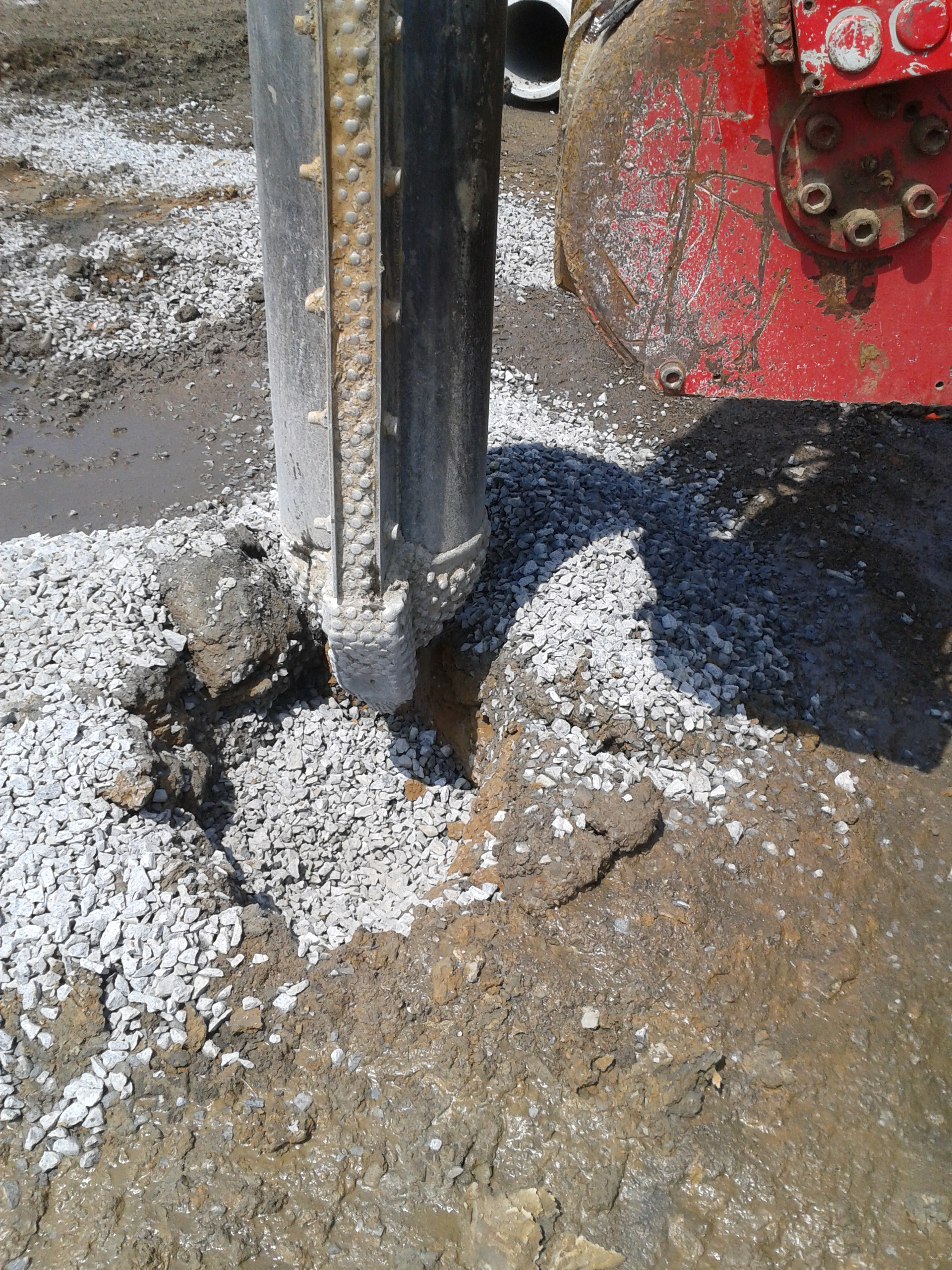
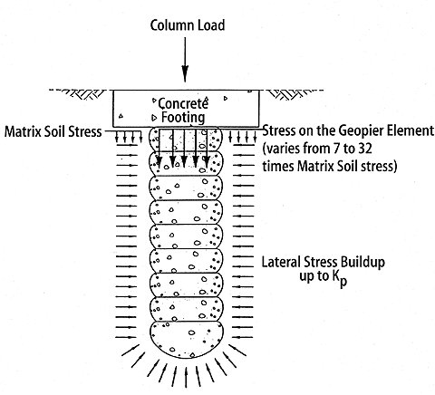
I sense John putting on his reading glasses now….rather than our typically taught shallow or deep foundations, these are known as ‘intermediate’. The rammer tool has 45deg edges to press the rock laterally – this ‘preconsolidation’ technique pre-strains and pre-stresses the soil below the drilled bottom, creating a bulbous base of aggregate upon which succesive layers are piled and compacted (each layer no more than 0.3m). The ramming therefore creates a very stiff dense rock pier (”load goes to stiffness”) but also improves the strength and stiffness of the soil surrounding the pier, through compaction >> increased lateral stress >>increased effective stress >> increased shear strength (Mohr’s circle) . It does however involve a huge amount of piers, 3600 for that matter under a warehouse approx 200m x 100m, but each rig can complete approx 50 piers per day; one more is inbound (with a top hopper). In this case no steel is being used, but it can be incorporated to prevent uplift.
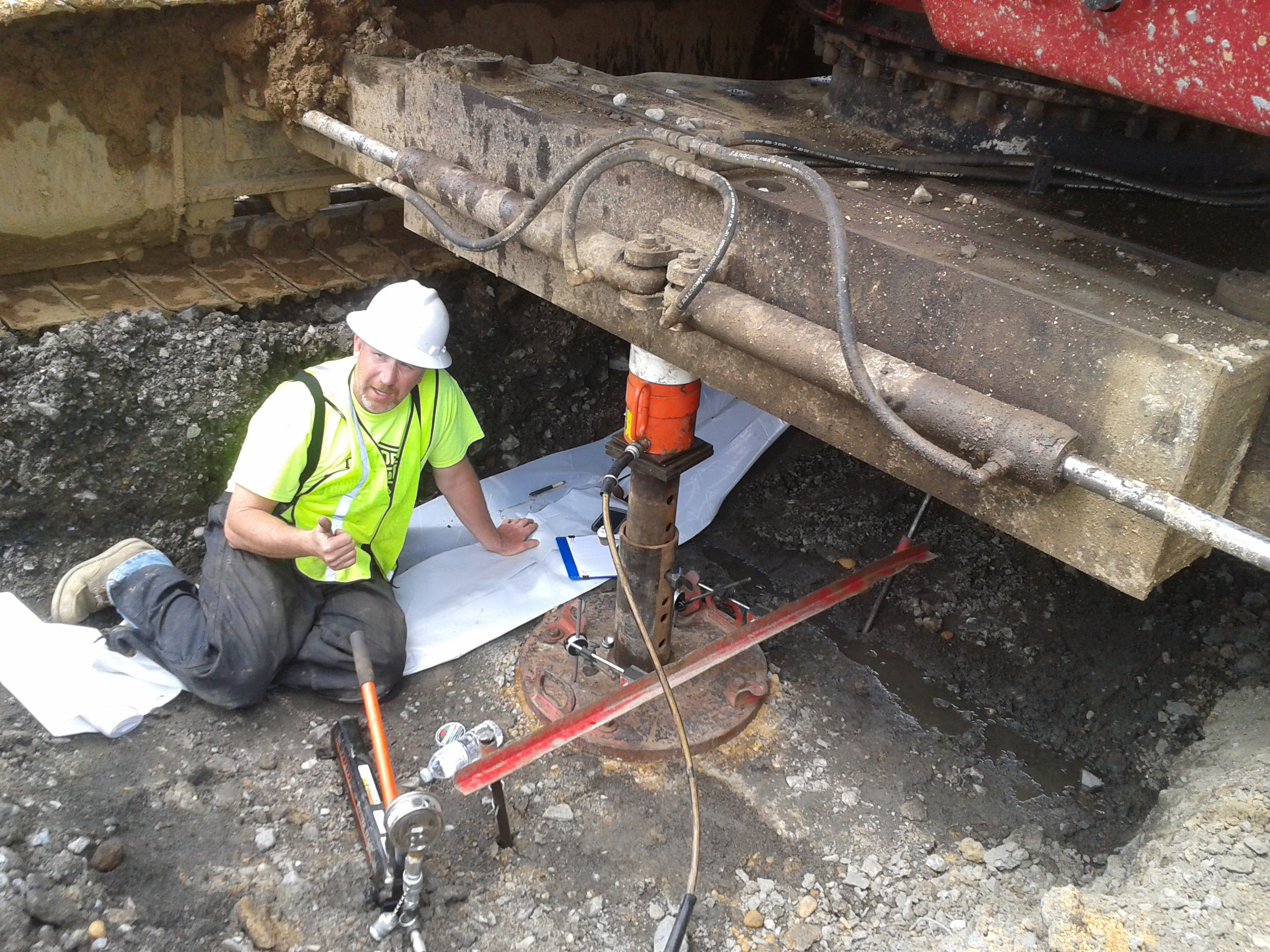
One day in we conducted the modulus test on one pier – the top foot (sacrificial) of pier was hoed back, while a pressure of double the design load was placed upon it (550kN/m2). Settlement was then recorded as pressure was increased, as was the rebound when pressure was released. We await exact figures and analysis but down and dirty figures were a total settlement of approx 8mm, with a rebound of 7mm – recall the consolidation curves.
In other news, we just enjoyed a long wkend (memorial day yesterday) full of BBQs with friends and family. Smoked, slow cooked, pulled pork is the food of choice for BBQs out here having eaten it 3 days in a row – certainly not complaining!! The SI joined us for a few days last week – no doubt he is telling tales of our 10ft rattlesnake fight on the Appalachian trail…I certainly am! Weather has now hit the 30deg C so the outdoor pool at work got a visit today at lunch – tough life!
Power Available?
The last few weeks have been hectic, subcontractors have been difficult to manage and we have invested a vast amount of time programming every room to give all subcontracts strict deliverable dates. This has included tons of work shops and study groups and now we can see the light as it will soon all be added to the main contractual programme to bring The New Children’s Hospital (NCH) back on target, loosing three months of delay in seven months of work, back on target by Christmas!!
However I have done a lot of work with the Power On Programme which needed to be changed to Power Available as Power On portrayed the wrong message, it basically means power will be available to be used but in matter of fact will only be on the HV side. This process has included inspections of the LV switch boards attached photo below there are six for the three substations and the UPS boards are yet to be built, and we started installing the HV switch gear yesterday.
The different colour are for essential and Non-essential. The front two boards are for the Northern Substation and Plant Substation is at the back, I re-visited yester day and they are a lot further ahead looking at Factory Acceptance Tests on the 6 June and delivery on the 9 June.
The next challenge is the Corridor of Death which is slowly progressing and I am trying to get the subcontractors to utilise the model which they are contractually to do as much as possible. We have had to move one Fire Hydrant Pipe which has been in location since last October as Fredon Mechanical Services Subcontractor modelled there pipe wrong and did not even model the brackets themselves. The corridor is becoming an increasing concern and we called in the director of the main problem child subcontractor yesterday to try and resolve some design and shop floor problems. This meeting will hopefully see change and progress watch this space for an update!
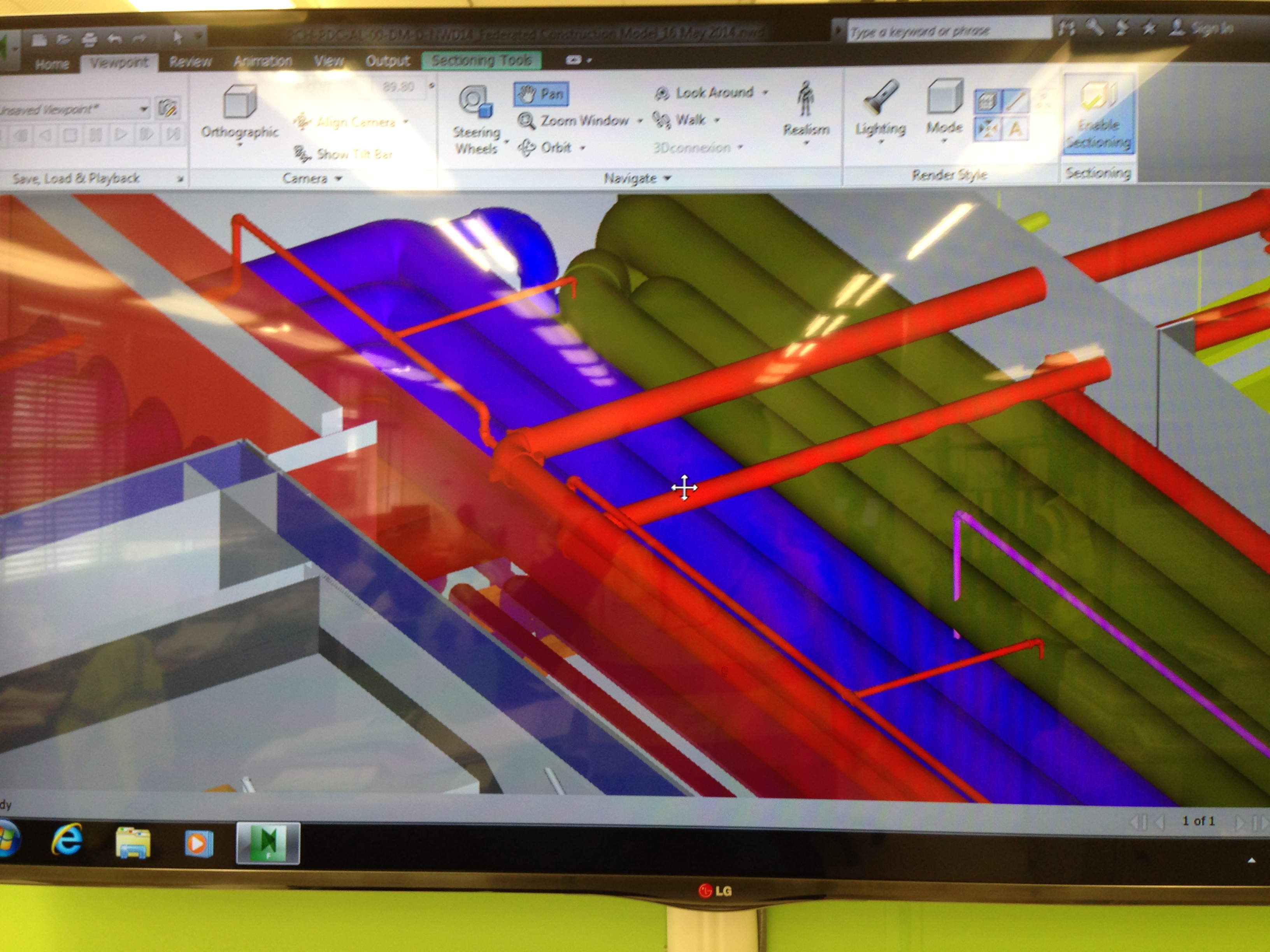
To prove we do use modelling attached is an area I am working on at the moment, the interface between corridor and main service riser.
We have also started to see progress in all the Plant rooms and these should start to progress over the next few weeks……
Like for like, but not quite…
The pace of life in Aberdeen is picking up and people are actually starting to ask my opinion and give me more responsibility. In the last couple of weeks there are two jobs that have taken up a significant portion of my time; the modification of lifeboats to increase their capacity and the modification of 34 cabins on the Clair asset. Both of these projects combined will go most of the way of increasing the capacity of the platform from 120 to 154, which is the key enabler for the turnaround next summer. The cabin upgrade is going okay so I’ll only cover the lifeboats in this blog.
The Lifeboats
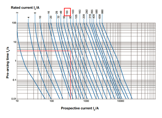
The lifeboats task has been rushed through a little bit and was supposed to be in two phases, with the first phase being like for like. Things have not turned out like that at all. Phase 1 is the recertification of a davit A frame used to lower the freefall boats into the water using a hydraulic pump unit (HPU); it is now definitely not like for like. Despite going through several levels of technical checks it turns out that the original 17kW motor has been changed for a 26.4 kW motor by the vendor and they failed to inform BP. At first it was assumed that the increase was because there must be a bigger pump in the HPU. However, this is not the case and it appears it was just the vendor standardising their HPUs. From their point of view it makes perfect business sense to standardise their units but it is criminal to not inform the client on what was supposed to be a like for like swap. As result of the change in motor there is now a problem with cabling. The current installed cabling is 6mm2 three core cable rated to 36A. Since time is very tight with when the job should go offshore the vendor is saying they cannot swap back to the 17kW motor and that the best solution is to de-rate the motor to 22 kW and change the protection device to accommodate the slightly larger motor. The calculation below is why this won’t work and why we are left with two options: 1) increase the motor and change the cabling or 2) leave the cabling and go back to a 17kW motor. What I have put below will be confirmed (probably more accurately) by WGPSN next week but this is what I think:
The old motor is rated for 17kW, with Ifl = 28 A
The new motor is 26.4 kW
In is the nominal current of the protective device.
The protective device is selected from a time – current characteristic curve where Istart up is 8 x IFL (for a motor) = 8 x 44.5 = 356A
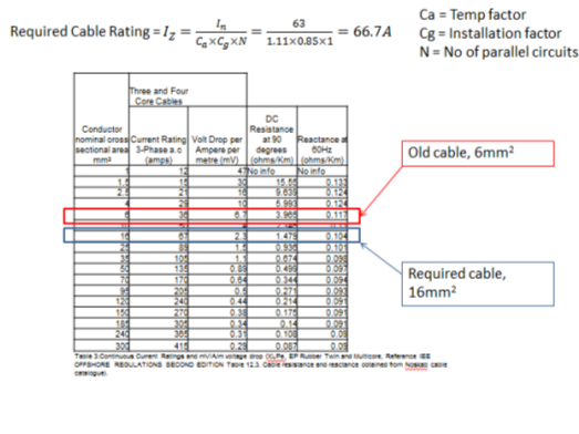
Should the cable need to be replaced then the job may not go offshore because it will involve someone from operations risk assessing the work because there are other live cables in the pillar that feeds the HPUs. The asset may not be happy with this.
Risk Assessment
The other phases of the lifeboats are pretty much on track but there has been a great deal of risk assessment done regarding the construction because there is overboard work, scaffolding, hydraulic fluid and new technology involved. The whole process is very meticulous but occasionally there is a lapse.
When asked what was the mitigation for hydraulic fluid falling into the sea the response was to use big Norwegian thumbs to plug the hole or do it at night so nobody can see!! That sounds more like a Sapper’s approach to risk assessment.
I must stress, this was a not what was captured as the mitigation.
I will keep you up to date with this task because it is due to go offshore for the scaffolding in Jun.
Other news
I have been sampling the delights of Scottish cuisine and have come across a strange soup and a deep fried Mars bar. I’ve not tried the soup, I’ll save that for Joe Wood when he comes to visit, but the Mars bar was actually quite nice.


Cakes and Pipe Jacking
I have been rather quiet as I realised that all I seemed to be writing about was what size cast iron pipe we unexpectedly uncovered on our drainage run and what was going on with the latest in the HV cable installation saga. Well nothing has changed there we are on big old cast iron pipe number 6 in the last 10m of drainage, the client are getting excited about us damaging the HV cables and we are now extended the HV sub station slab because they put the wrong size GRP housing on top of it.
At the end of last week we had a team meeting to discuss roles and responsibilities as the Project Director has realised that they may have scrimped too much on construction management staff. We have no resident temporary works engineer or quality assurance person and these are the areas that the project are crashing and burning. At the start of the week I was looking at a promotion to being the resident engineer of the block G construction-think Ex COFFERDAM but 40m wide and 100m long with 2 stages of propping! In the initial meeting I pointed out that they might want to consider the detail of the connection of the waler to the sheet piling as they were suggesting a 1m gap to allow the construction of columns. They said not to worry about it as they would use wedges, until I pointed out that wedges spanning 1m taking vertical components of the forces probably wouldn’t work! So they went back to the drawing board and asked to move the columns in a bit!
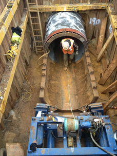
OIC Power and Drains again! But this is taking an interesting step as we are planning our pipe jacking exercise to tunnel under Battersea Park Road. In a nutshell the masterplan is to build a cofferdam to launch the pipe jacking machinery to cut a 70m tunnel approx 5m BGL to meet with an existing sewer on the other side of Battersea Park Road. watering scheme.
Pipe jacking launch shaft in top left corner tunnelling 68m with the final 30m under a raised section of the Battersea Park Road bridge: and a typical pipe jacking launch shaft:

General works:
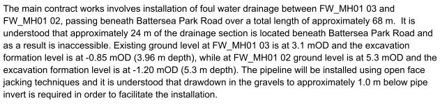
The main issue is one of John’s favourites: GROUNDWATER! In the foul drainage run we have had to sump pump a considerable amount of water flowing through the Terrace Gravels, which is also slightly tidal as we are about 300m away from the river.
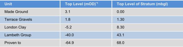
![]()
The plan is to control the groundwater with a de-watering system:
Likely issues:
-Proximity and state of dilapidation of the Battersea Park Road Bridge.
-Proximity of Network Rail lines.
-Risk of settlement of bridge foundations.
-Risk of encountering unknown services or obstructions.
-BOUNDARIES/PROPERTIES-although we can’t be tunnelling through much worse than the gravels which will be pouring water in! Unless we hit an old brick pile or more of the old gas works infrastructure.
-GROUNDWATER-we are pretty much in the worst case scenario.
-CONTAMINATION-So far we have been OK with de-watering around the site so fingers crossed it can just go down the foul sewer.
Without looking at my notes they were the main points I remember from John banging his hand against the wall! No doubt I will have more to write on this over the next few weeks.
On a plus point I held a Colossal Cake Sale for Help for Heroes in the canteen and we made £220. I mentioned to our Environment/Schools/PR person that I could come in uniform and she held me to that offer. The problem was mine was all in the attic in Poole. So after a quick cycle to a friend’s house 5 miles away I squeezed myself into an ex-Army Air Corps Adjutant’s tailored(!) green kit to sell our cakes for an hour. I was overwhelmed by the generosity of some of the guys on site and the support from both the managerial staff and groundworkers. Not a bad outcome for a couple of hours work.

Fighting Fire with Fire
The last couple of weeks have been dogged with industrial action, which has resulted in the loss of around 4 days work. The dispute is centred around a change to Australian legislation governing the access of union officials to site. Previously, a union official could access any site if they deemed that there was an urgent safety issue, and demand that work cease until the issue had been resolved. This translated to a carte blanche for union officials to wreak havoc on construction programmes, and chuckle while site management frantically tried to replace a first aid box that had a broken seal, for example.
The new laws require union officials to give 24hrs notice to site management, so as to enable them to rectify the issue without having to stop work on the site. This has gone down badly with the unions who are doing their best to beat major companies (as far as I know, this is not restricted to John Holland) into flouting the law and allowing immediate access. The tactics to date have been to call 2 hour union meetings, which they are entitled to do. The clever part is that they will hold meetings for select trades at different times of day so as to ensure there are never enough of the right people on site to pour concrete.
There have been several incidents of union officials turning up on site and gaining access before John Holland staff have a chance to respond. The JH head office response has been to employ an Ex Columbian Army Commando to guard the site – hence the blog title, fighting fire with fire. Whilst he really does look the part as a visual deterrent, it would be severely frowned upon if he were to employ his ninja skills to scalp a union rep at the entrance to site. As such has been instructed to call the PM if he sees anything. His presence has also antagonised the union members; an outcome I think most of us could have foreseen.
Switching subjects, I was hoping for some advice from the floor. As we are about to pour one of the level 5 slabs, the Building Code of Australia suggests that we are obliged to have a fire hydrant system and fire hose reels in place and working up to level 3. Several JH staff members are concerned with the security of the fire hose reels, particularly as we are in the middle of a Uni campus and the little scrotes have accessed site after hours on several occasions. I only need to think back to the time Steve Crosby-Jones emptied out a 30 storey tower block of students after a couple of beers at Cov Uni, to gauge the likelihood of turning up to a flooded site in the morning. This site isn’t particularly hard to access so the security of the hose reels will need to be localised. It will also need to allow easy access to use the hose if required. Does anyone have any experience / suggestions that they could share?
I have included a picture of one such fire hose reel to help you visualise the problem.
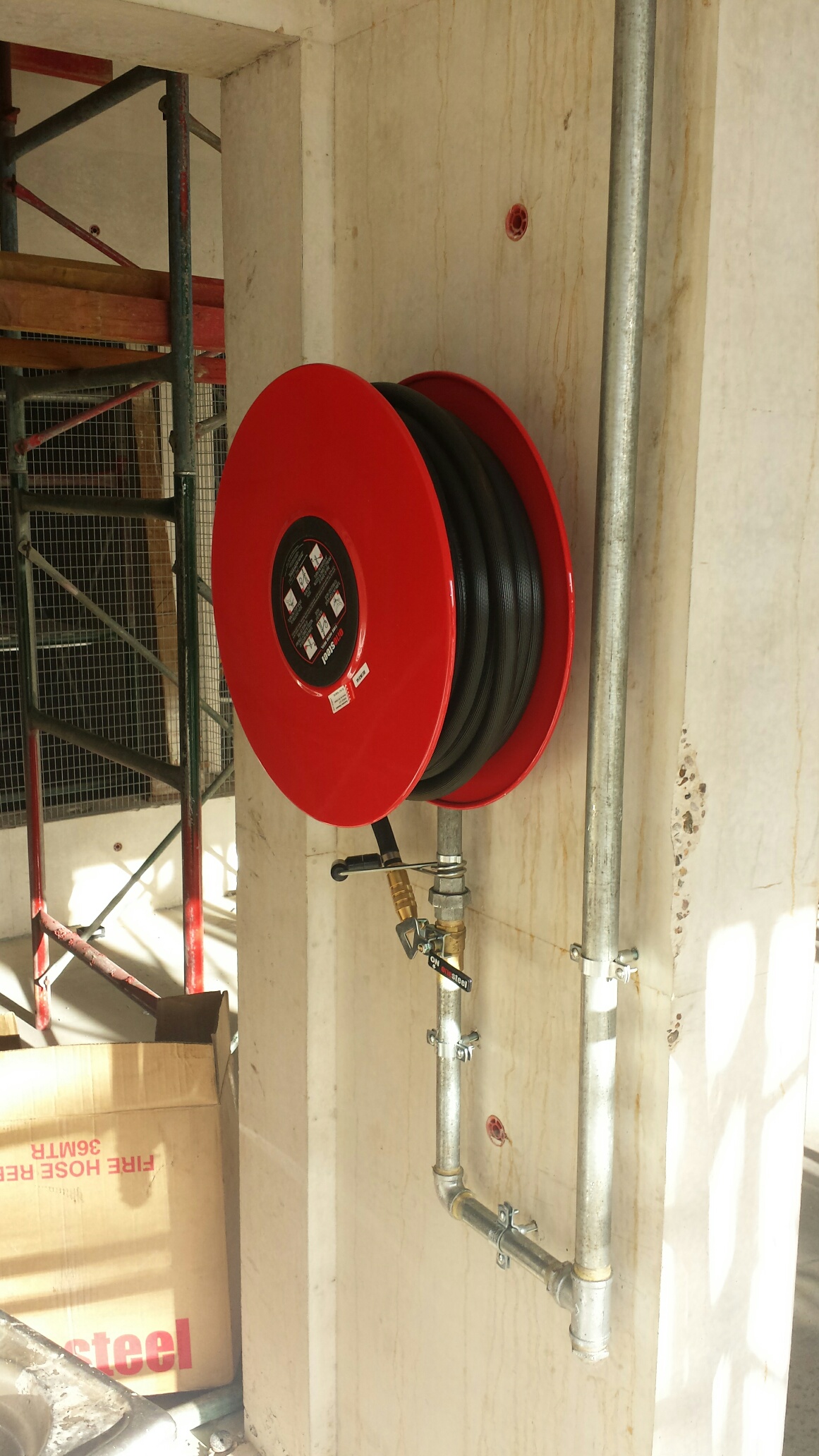
Fire Hose Reel on Level 2
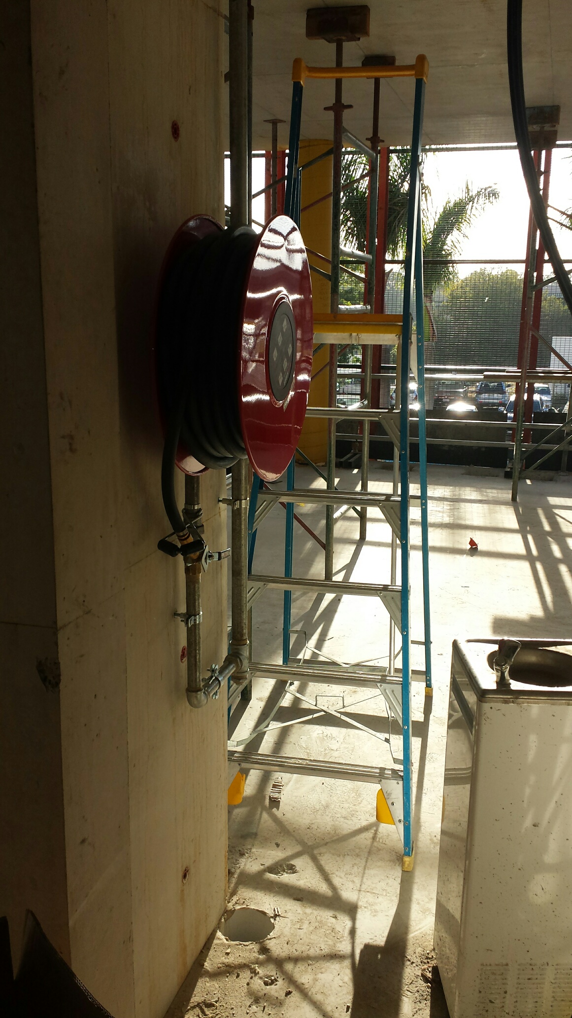
From the other side
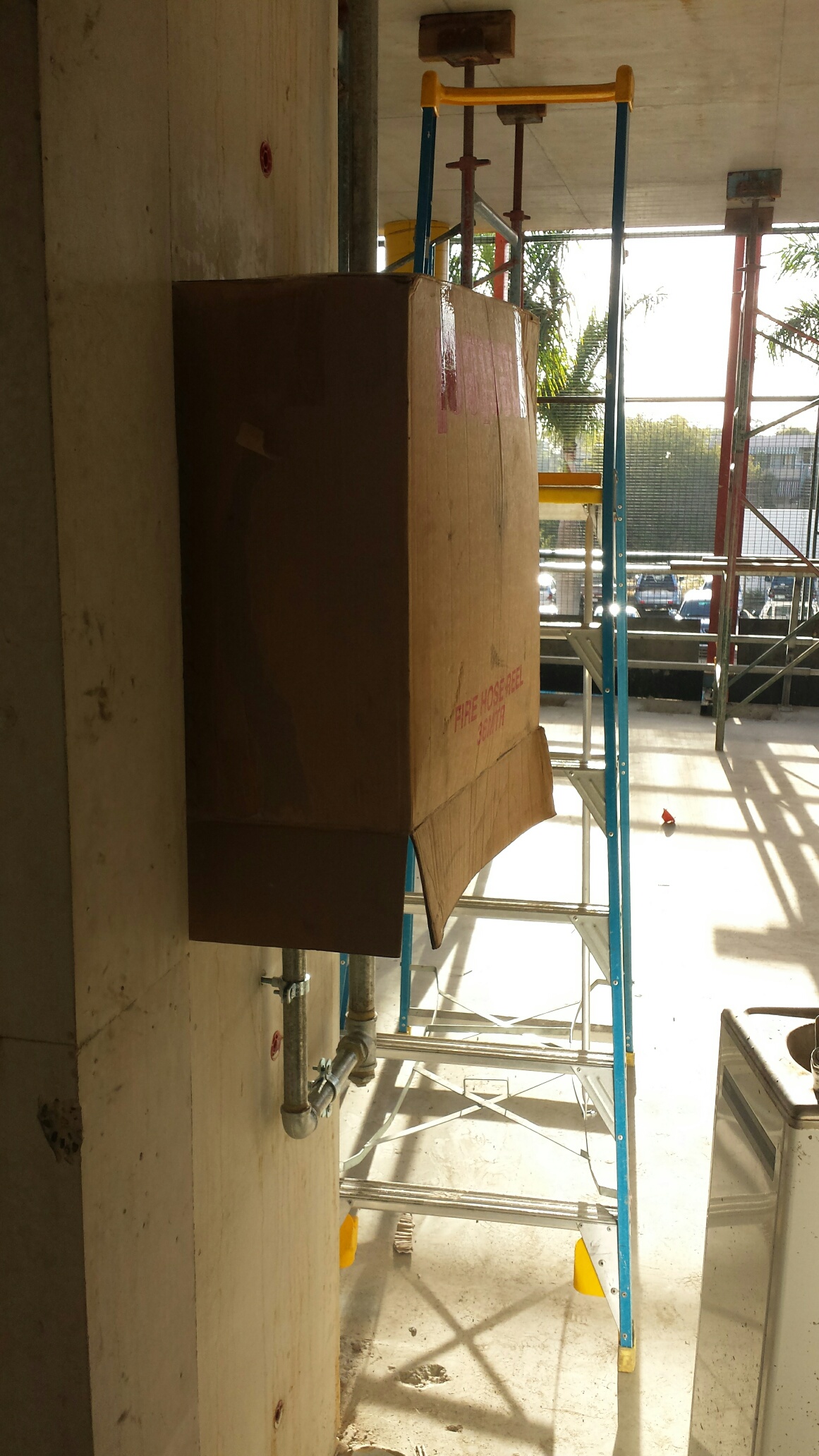
Demonstrating the current protection.
In other news, we had a work trip to see the Brisbane Broncos play the Gold Coast Titans on Friday. Those who know me will appreciate that a fair few beers were consumed, particularly as it turns out that my boss is even more of an animal than I am! The result was me doing the plank on a kerb stone whilst trying to get rid of hiccups at 3 in the morning.

The plank!
I’ve got piles…in the ground
I’ve spent a lot of my time checking and re-checking steel reinforcement schedules the past 2 weeks. I have very little confidence in the scheduler appointed by the steel makers (Onesteel), and I have picked up numerous mistakes. Some of them may be innocent, but others are obviously in hope to sneak in extra steel as they are paid by weight. Our client will only pay us based on minimum lap lengths, and have issued what they expect the schedule to be, however I have found mistakes in their schedule too (wrong diameters of bars that do not match the drawings issued to us). This made me dig deeper and it seems they are also not following the bar bending sizes in their own standards. There is also some incredibly difficult reinforcement to make work in the headstock. This has been put off for some time due to firefighting other more pressing issues, now it is crunch time. Everything is complicated due to it needing to sit in a glorified bathtub 6m up in the air (just a really big 20 tonne, 12.5m formwork bathtub). SO I’ve been trying to draw lig sets that sit inside other closed ligs (The magic trick with 2 steel rigs that click together springs to mind).
Piling progress has been painfully slow. The brand new hammers that came from Singapore have not been dropping consistently. We thought that one was fixed on the second rig (the manitowok), but then it started to blow hoses. So 3 days were lost due to replacing all the cheap Chinese hoses with high pressure ones made in Australia. Thankfully, it now seems to be working OK, so its moved to pier 3 and started on the Southern end. This is where the critical path is, and where the bridge needs to start getting built from. The casting yard is to the South of the main site and the sequence for girder casting has always started at pier 3. The work done on the North of the site was just to keep the piling rigs busy till the access track was completed. In effect buying us time.
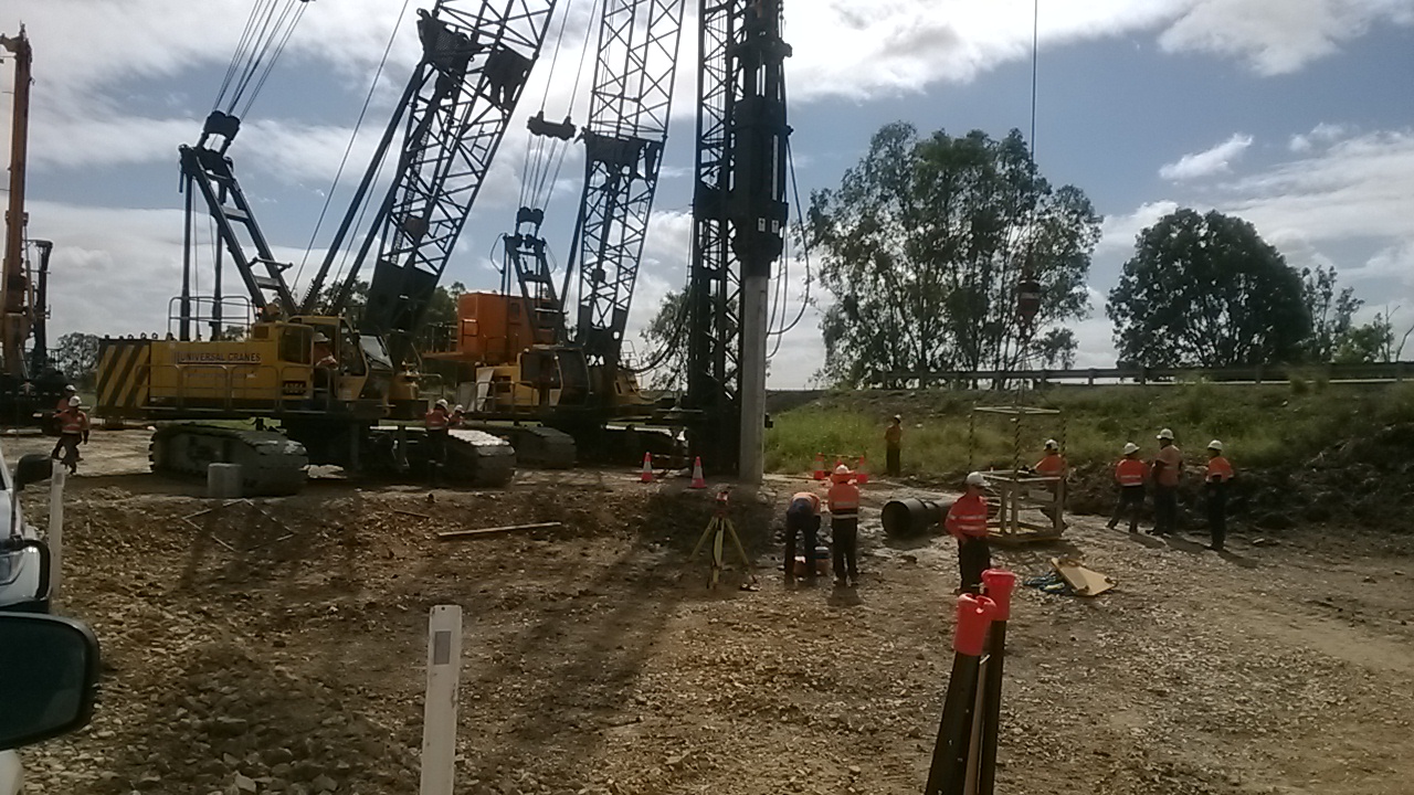
Rig 1 (the Waltman) is still suffering from inconsistent blows every 50 to 100 strikes. After 3 experts have been flown over from Singapore, all with a boxful of parts it seems to be getting better. As I type it is moving from the North to the South of the site to start working there on Monday. By my count the pilers are now 2 and a half weeks behind schedule. I’ve lost time how many iterations of my program I’ve gone through now, constantly changing the plan to meet what can be delivered by the pilers.

The 2 test piles that need to be tested with PDA were finished by rig 2 yesterday. The first one came up well with about 4000KN once it hit the weathered rock layer we were aiming for, however the second one hasn’t (Its at the opposite end of the pier). It could be that the rock layer is deeper here). I called a stop to the driving at the limit of the overdrive allowance as if we drove any deeper there would need to be a lot of remedial work done in fixing up pile to ensure sufficient splice length in the pilecap. While there are ways to deal with such an event it has not been covered or costed in the contract. As such if the client want us to go further than their design we will need to be instructed to and will cost the works accordingly. I’ve also learnt how to use the PDM machine, in the event of someone being off sick or on holiday. It’s a fairly simple bit of kit – I just need to get better at the calculation done following the data gained. And learn CAPWAP for my TMR…

Running parallel to this I’ve been finishing the beast that is the substructure methodology and AMS. This needs to cover all the risks involved with everything from breaking down the piles, excavating, formwork installation (for pilecaps, columns and headstocks), concrete pumping and then stripping the forms. This will take up a lot of my time in the coming week as we near the first pilecap excavation. Oh and the pile cropper should arrive this week, I’m sceptical as to how much time it will save us, but I will let you know in the next blog…
Oh, and the crossing across Scrubby Creek is finally finished.

And now for my next project……
Like my colleagues, the blog has been on hold whilst I finish my thesis. Since then it has been hi tempo in the office too, as we complete (mostly) the Marine Terminal HVAC design and start on a UAV hangar design in upstate New York. As rather a lot has happened in the last few weeks I shall try and make this bite size.
Quantico: My invitation from the USMC meant I was able to sit in on a 1 star R&D briefing on the latest energy saving measures to be implemented. This included not only changes in policy but a whole host of kit that can either harvest or generate energy to supplement current needs. This includes boots that can charge your radio batteries as well using waste generator heat to wam up shower water. A very ineresting experience particularly as the USMC seems to have less money than we do and is getting industry to do the research for them rather than doing it themselves for the sake of those lucrative government contracts. Needless to say some of this experience ended up in my thesis.
Caven Point: As with all design project coming to an end, this has been a period of mind changing and total redesign. This including swapping ouot VRF for VAV systems, totally removing VRF from workshop areas and changing all the asociated air handlers, make up air units, louvres, fans etc accordingly. Then at the 90% we received requests for additional items including, extra partition walls in large office areas (total recalculation for the room(s) and equipment resizing), changing A/C to just ventilation in three warehouse rooms (more equipment redesign), Air Curtains over all roller doors (to stop flies and heat loss – a ‘helpful suggestion’ to the end user from one of my team) and all this with a week to do just after the thesis deadline. The lack of communication between the design team has beenthe biggest frustration in this period. It still happened that every day I log on and there is a change on the drawing that affects me considerably or the user has realised that something is not quite as they remember asking for and needs changing. Part of the game I know but the inability to stick to the design requirements set out at the beginning of the project has added delays. The whole process is so rushed that any Contractor taking this on stands to make a fortune in changes due to design issues. At least I won’t be around when that happens……..
Fort Belvoir VCC: I attended the project kick off meeting in early April which turned out to be a classic case of ‘You can lead a horse to water…’ with some of the shareholders. To recap, this is a visitors control centre which processes people attending mostly retirement functions who are not DoD employees. A glorified guard room in short. However this facility must also be a 24hr facility, blast protected and strategically placed, just in case the worst ahppens. Located after the turn in to base but before the main gate, it is still a design that needs refining hence the meeting. What started off as formality eventually ended in a 3 hour contradictory argument. But to explain this I need pictures:
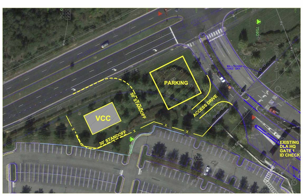
Option 1 the Garrison Teams favourite optioin
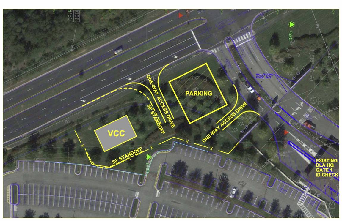
Option 2 Everyone elses favourite
From the start the Garrison maintenance team said option 1 was the only choice. We questioned this because it clearly interferes with traffic going in to the main gate, causing a potential bottleneck which stop entry to the post or could easily be missed in which case the only way to get back to it is to go on to camp, turn around and go back on the highway. We were politely told this would not happen because the only people using this facility were going to be going to retirement parties normally held mid morning, coming infrequently and that people turning around behind the gate is just what happens (I should add that this is the most heavily guarded gate I have seen in the US!). When we pointed out option 2 offered a far less likely chance of causing obstruction because it could be accessed off the main highway and if we made this road 2 way and no one would ever need to go through the gate in order to turn round, thus improving security. We were told that this choice would obstruct the rush hour traffic on the highway because up to 100 people could need passes all at the same time, any time of day (probably rush hour) and that the gate guards were quite happy waving people through to turn round! There was still no resolution after 3 hours so it was left to an admiral to make the call. I think he diplomatically chose a design that was a compromise. From the mechanical point of view, one of the staff was keen to get renewable energy in to the building. They wanted solar water heating and a geothermal heat pump. We presented the case that solar water heating was not financially viable for a single toilet sink and that a geothermal heat pump would be $40,000 more than air source heat pump and would take over 30 years to pay back. The customer went away unconvinced that money should be a barrier to green technology!
Fort Drum UAV hangar: Because the VCC was so small I was given the chance to put my radiant floor heating research to the test with my next project. This is $30 million UAV hangar in Northern New York State where the minimum temperature is around -30 degrees and 35 degrees in the summer. Most of the building is a standard design but the loads for the location need to be recalculated. However the hangar floor (25,000 sq ft) is going to require full underfloor radiant heating and no one in my department has any experience so I get first go! We have no design software for this so it is back to hand calcs to work out all the losses etc for sizing. Still no idea how I will draw this system either. And a 65% design is due in 2 weeks!

A UAV hangar
OPD: In the USACE Officer Professional Development course we are given the chance to get an insight in to the responsibilites of the District from the eyes of the Commander which means seeing some pretty interesting stuff in the local area. We started with an American PFT complete with 2 mile run, which we all passed, before heading off to the debris vessels. These are used to keep the water ways clear of logs and other debris as well s scooping the bodies out when aircraft land in the Potomac. Next was the Springfield site where a specialist team was clearing mustard gas and UXO from a former university house basement using equipment that would not look aout of place at USAMRICD. This required great tact from the team in dealing with the public who are understandably twitchy about having UXO in theback yard! We visited the Washington Aquaduct to see how USACE produces most of the water for the DC area before a visit to the new Intelligence Community Campus Building. The current buildings are being ripped out, including the fascade, then are being rebuilt as lecture facilites to meet modern code as they were nearly all built in the 50’s and 60’s. This propject had encountered numerous problems with the public, who did not want to see any new building and were against all construction (even if it is in the National interest). This resulted in delays and a reduction in height of the multi storey carpark so that it is below tree top height. Our next day started with a VIP trip to the Pentagon. This building is absolutely enormous (2.4 times the floor space of the Empire State Building) and was modernised recently to be a little town with every single type of shop so no one ever needs to leave. We were given a brief on the role USACE plays in the DoD and then saw the site of the 9/11 impact where a Chapel of Reflection commemorating those who died, is located. After a hasty lunch we tool the metro to the Capitol Building where were given a guided tour which included showing us the few areas the British did not burn down in the War of 1812. We are able to see the Senate debating but this was not that exciting with only 2 senators in the chamber. The final part of the experience was a trip to Arlington National Cemetary which is managed by USACE too and is still Army property. The plot size is enormous and they are having to expand to meet the projected demand until 2050 (barring no more major wars obviously). The most impressive part was seeing the guard change at the Tomb of the Unknown soldier. If you think you can do rifle drill, google this and find out how it should be done!
And in other news:
The weather has been a little unpredictable recently, with a retaining wall collapsing that took half a street with it in central Baltimore. The rivers rose 6ft in 12 hours and we are getting the same again tonight. Wildfire season has started in California which only mention because the USMC base I was invited to in order to see the demo of the equipment mentioned at the briefing has just been evacuated!
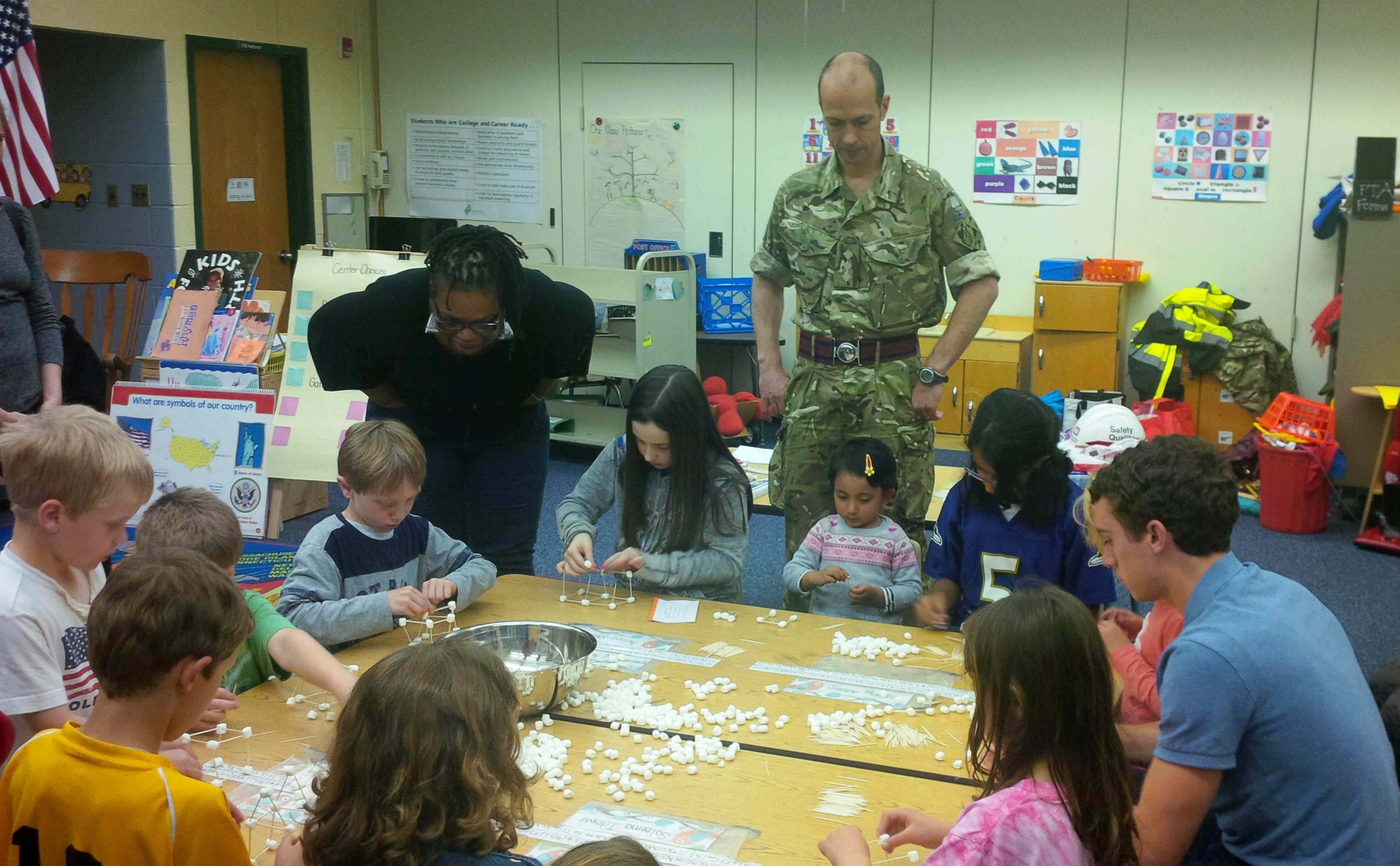
I was able to volunteer for a STEM evening at a local Elementary school where the kids learned how to build bridges using toothpicks and marshmallows. This was optional for the kids but amazingly we had 3 full classes and a merry time was had by all.
And on the home front Warrick is really enjoying baseball and develping a good swing, Ava has now turned 4 and we are making the most of the last few months by day tripping to New York, Philadelphia and Amish country with a break in Ocean City due in 2 weeks. So much to do so little time……
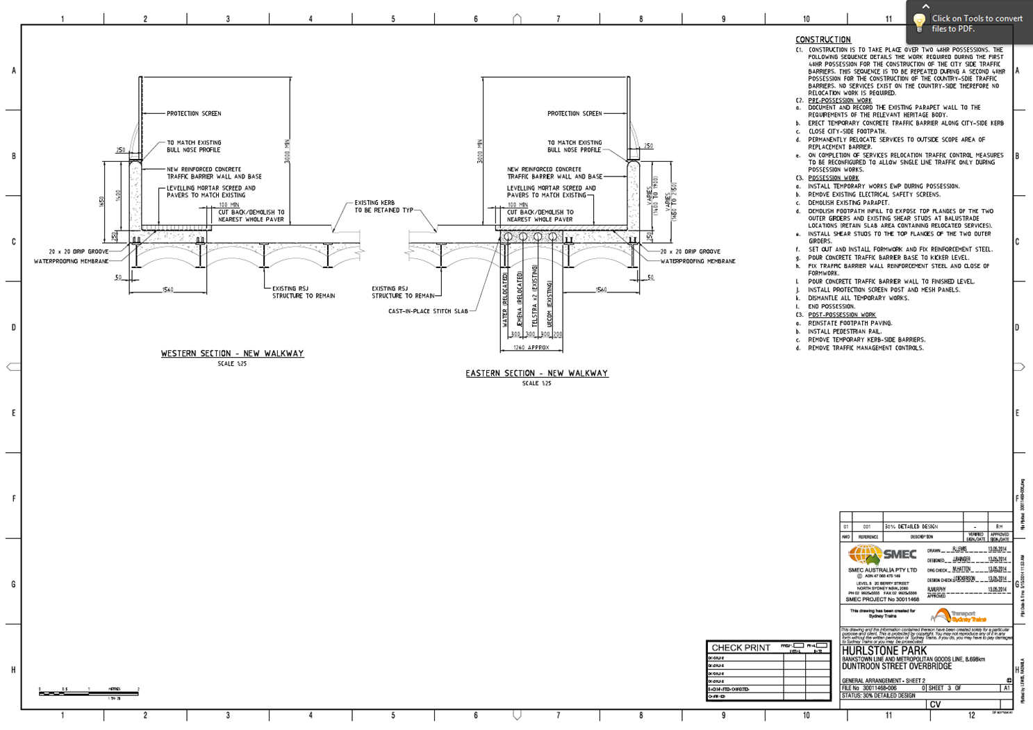
Bridge Parapet Traffic Barrier Design
It has been a while since my last offering but now that my thesis is in and forgotten for the time being and I have finally started my CPR reports here is an update on life in the design office.
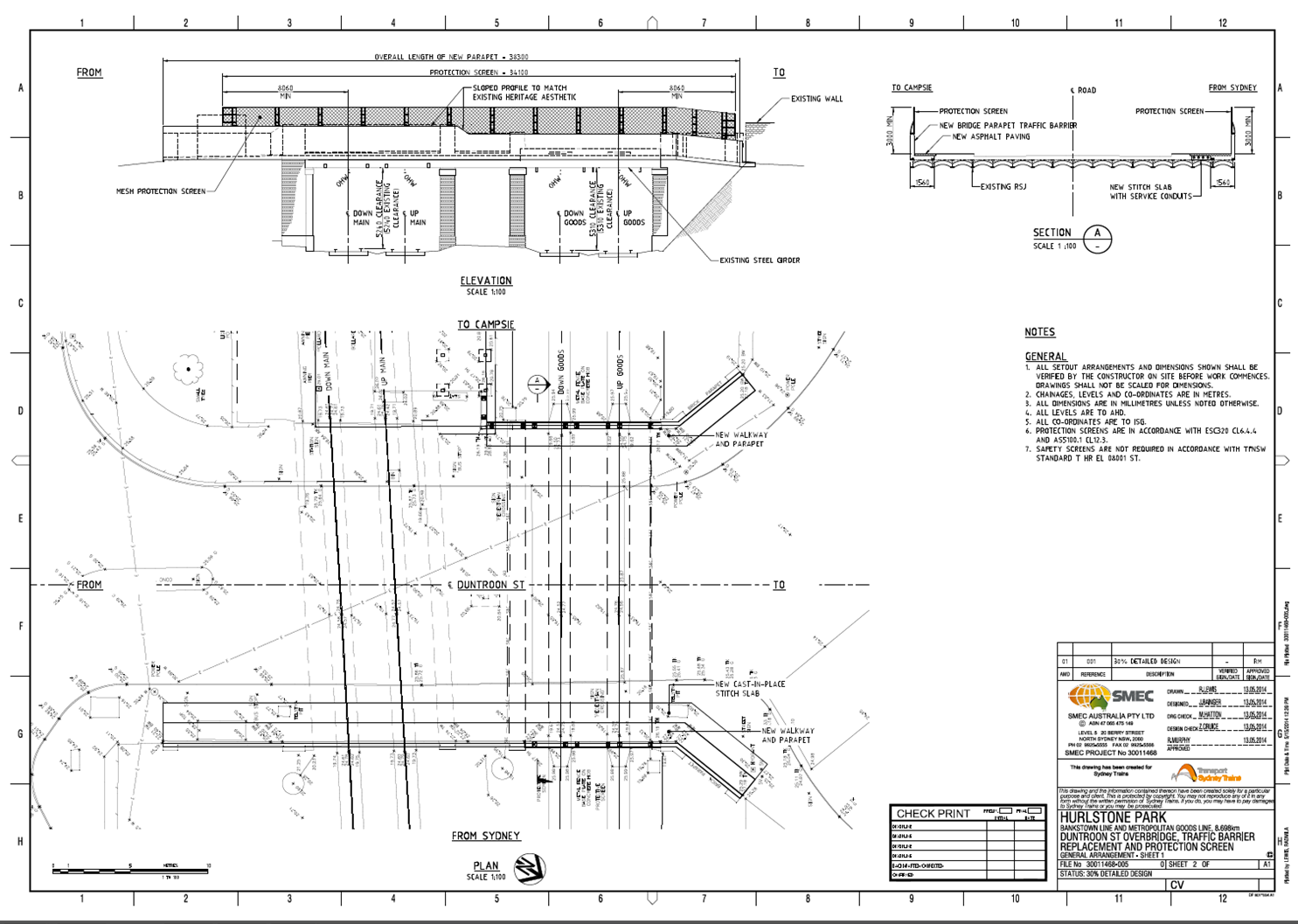
I seem to be the popular choice at the moment to compile and submit tenders, which doesn’t seem to be affected by the fact I have not won any yet because I have just received another one (no doubt my last) while also currently managing three design projects. Over this attachment I have been involved in nine projects (6 tenders and 3 design/PM). The one I have been working on intermittently over the last few months is the detailed design of a traffic barrier to replace an existing masonry parapet in order to comply with current standards. I have subsequently designed a cast in-situ barrier to be constructed on the outside of a 100 year old ‘jack arch’ rail overbridge. I have also modelled the bridge using Microstran to see if the existing structure can accommodate the traffic impact loads. A traffic assessment at the concept stage identified that an intermediate traffic barrier performance was required which stipulates an outward horizontal load of 180kN at 1.1m above road/footpath level, as well as a longitudinal load (to be applied simultaneously) and a vertical load (to be applied as a separate load case). The Australian Standard AS5100 (Bridges) does not explicitly provide a detailed analysis procedure for bridge barriers. As a result, current practice uses American Association of State Highway and Transportation Officials (AASHTO) design procedure based on yield line analysis. The design deliverables for the project are; Concept, 30% detailed, 70%, 100%, IFC. I have just finished getting the 30% DD drawings together to submit to the client (Sydney Trains) by the end of this week in a hope to have the 70% design complete and submitted by the time I leave. I have had to commission a Statement of Heritage Impact (SoHI) and I am now in the process of getting the environment team to produce a draft Review of Environmental Factors (REF) that may be affected by construction such as dust, noise, heritage, social and economic impact to the area. Because it is an overbridge that spans over two rail lines the work will impact rail services during two planned 48hr possessions as well as closing one lane and possible both to vehicle traffic during construction. The amount of work and consideration involved for all aspects of the project all stems from successfully identifying the stakeholders at the very start and you soon realise how many people, organisations and authorities are involved in successfully implementing a project. Below are the drawings at 30% design not showing reinforcement.
I have also been involved in ongoing managerial aspects with the maintenance centre column repair design as per previous posts and a fire protection upgrade design on a cable shaft at central station in the middle of Sydney CBD. I have not carried out any design for this but I have been given the job of PM to bring the project to completion. I also recently submitted a tender for a 1.7km cable route design which was valued at just under $300K with a rather vague scope of works. There was little time to clarify or ask for more detail on most of this – largely because of the fair tendering process every consultant must be informed if a question is asked and meanwhile you lose precious time which you may not have – so I compiled it based on the site inspection and project brief. The client (Sydney Trains) subsequently came back to all the consultants that submitted a bid and have changed the scope somewhat. It appears they put little thought into the original brief and this additional information contradicted previous information. I subsequently revised our originally fee to just under $400K having it reviewed by senior management. The whole episode made me view the client as very unprofessional and rather annoyed me. For instance one comment stated that all assumptions in our proposal should be deleted and the proposal should be based on factual information and the fee should account for the risk accordingly – what planet are these jokers on? It seems very odd – and the seasoned pro’s in the office viewed this in the same way – that the client expects to be entirely risk free. Especially if their own SoW is woolly at best. One of the first tenders I did had a 1000 page brief with various attachments and it was almost too much information, this was a 3 page brief with a rather ‘chip shop’ ppt presentation attached to it. When trying to compile a lump sum fee it very difficult to try and price a project when you haven’t got enough information but you want to be competitive. If the client is not clear on what he wants and asks the design consultant at tender that he is to tell them as part of the scope – which seems quite common in Australia – then surely the client must accept a certain level of risk because the supplier will have to make even more assumptions at the tender stage due to lack of clarity. I would be interested on everyone’s views on this and wonder if any of the other phase 3 lot have been involved in tenders and have had similarly clueless clients?
On other news, the family enjoyed a nice cruise up the eastern coat of Australia at the start of April up to Cairns and the Barrier Reef which was great. Ethan is like the energizer bunny and never stops. Being on a ship meant it was an easy way to travel as your hotel goes with you and by the end of the holiday everyone seemed to know Ethan by name having seen him run about the place for the past 2 weeks with me calling his name trying to keep track of him. It is hard to believe he was only 6 months old when we arrived in Australia and he is now fast approaching his 2nd birthday and Pip is now 5 months pregnant with no.2!

Rejected concrete
Saturday 3rd May has become a dark day on the progress of the Liverpool street station. Following on from the success of the level 106 slab the level 101 slab should have been more straight forward. The amount of concrete to be poured for the 101 level was calculated at 220m3 which was 100m3 less than the 106 level. In addition the steel fixers had work extra shifts to ensure that all the steel was in place prior to the pour, the 106 level had seen steel fixers completing the steel as the concrete was being poured.
With all this in place the pour should have taken only six hours however 8hrs after starting, the pour was not complete. The principle delay to the pour was due to the poor standard of concrete that arrived at site and a miscalculation in the quantity required, with a further 7 loads having to ordered.
At the pre pour meeting on the Friday I had raised my concern over the fact that the previous pour had seen concrete being pumped into form work before the slump tests were complete. If any of the slump test had failed dramatically we would have had severe difficulties in removing the failed concrete or even identifying were it had been poured. In my mind this would have meant the entire slab would have not met the required strength. With my concerns aired I found myself armed with the clip board and in charge of the slump test. Unfortunately this would result in me being struck of many a Christmas card list. The concrete supplier, Cemex, had won the contract based on price. Although I don’t have the exact contract comparison details, I have been informed that Cemex use their own brand of additives to keep cost down however this would seem to have disastrous consequences on their mix.
The concrete specified was a C50/60 mix and the slump was specified between 580 – 620 average diameters. The first delivery of the day managed a less than impressive 520mm. A discussion with the site engineer saw the concrete accepted. However the second delivery spilled off the slump testing board managing a estimated diameter of 680-700mm. Further discussion with the site engineer and the Cemex technician saw the concrete accepted with promises of improvements in the mix. However this inconsistency was set to continue and of 34 loads (full load 7.6m3) of concrete on order I ended up rejecting 6 loads with the majority of the remaining loads being highly questionable. Many of the questionable loads that were accepted were overly loose rather than stiff. Despite failing the slump test they were accepted on the basis of perceived risk of the concrete reaching the required strength against the risk of creating a cold joint.
A cold joint is formed when the time between concrete loads is sufficient to allow the curing of the poured concrete to be different to that of the next load, ultimately creating a concrete joint. As the position of this joint can’t be controlled this can result in a weakness as this may be at a steel reinforcement lap joint or an area of steel without the required anchorage to achieve the required tensile stress.
The risk was transferred to Cemex with verbal and written confirmation that the concrete will reach the required strength. Despite this reassurance from Cemex this does not sit easy in my mind as the question that was not addressed was whether the concrete strength would be reached in time to allow us to strike the formwork and then to excavate.
In addition to the structural issues the loose concrete also prevented the power floating of the surface to achieve the required smooth finish. Power floating requires the concrete to be firm enough to be stood on with enough flex to allow the power float to smooth the surface. Three hours after completing the pour the concrete was to loose to power float and a paddle finish had to be used to complete.
This has thrown up a number of contractual issues concerning the strength and finish of the concrete. The concrete was required to meet 30Mpa cube strength in 24hrs, however this took over 48hrs to achieve. The delay has had the knock on result of delaying the excavation through the 101 level to the 95 level. With over 3000m3 of soil to remove the two week excavation to working level is now going to be very tight with very little scope for further delays due to unforeseen ground conditions. The finish surface of the concrete is to be exposed the paddle finish applied as power floating could not be achieved has had to be raised a s a ‘Non Compliance Report’ and negotiations with the client and designers have continued throughout the week to seek a resolution and to avoid arbitration.
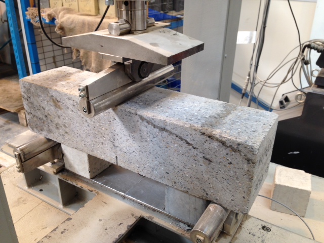
Strong as a Kit Kat – Part 2
The last blog saw me trying to understand the issues surrounding the high failure rate in the concrete in the primary lining, with respect to flexural strength. In a pincer movement reminiscent of the Zulus at Rorke’s Drift, Richard and John exposed my mild bluffing surrounding the testing procedure….
So here is me attempting to be John Chard…
Why test for flexural strength?
Concrete is a brittle material with a low tensile strength. Adding steel fibres to the mix will enhance toughness and ductility defined by the BS as follows:
Toughness – the ability of fibre reinforced concrete to sustain loads after cracking of the concrete ie its energy absorption capacity
Ductility – general ability of the material to sustain load beyond a yield point that defines the limit of elastic behaviour (onset of cracking). (Concrete without reinforcement would be brittle and demonstrate an abrupt loss of strength beyond elastic range.
The sprayed concrete that delivers the structural propeties of the tunnels is steel fibre reinforced (SFR).This ensures that the structure is able to sustain significant ground movements without sudden brittle failure. Therefore the trials procedures will seek to test the ‘Residual Flexural Strength’ ie the flexural tensile strength retained after cracking.
Testing
The CrossRail specification for Sprayed Concrete Linings specifies BS EN 14651 as the test method for approving:
1. Flexural Strength
2. Residual Flexural Strength
The test beams are centrally loaded as shown below, by the 3 point method. The specimens are notched at mid span to induce a crack via stress raising
Performance of the test sample is specified by the relationship between the applied load and the Crack Mouth Opening Displacement (CMOD). This measurement can either be measured directly, or calculated in terms of central deflection
Measurements are taken as follows:
F(L) is the load corresponding to the limit of proportionality (LOP)
F1 @ CMOD1 = 0.5mm
F2 @ CMOD2 = 1.5mm
F3 @ CMOD3 = 2.5mm
F4 @ CMOD4 = 3.5mm
The slide shows a typical graph of load, F, against CMOD (BSEN 14651:2005)
Flexural Beam Test Correlation
Flexural Strength
f(L) is calculated in terms of the centre span load, F(L) as follows:
f(L) = 3FL/2bh
h = depth of beam above the notch
b = section width
L = span
Residual Flexural Strength
Crossrails specification tests values of residual flexural strength @ deflections of 1mm and 4mm respectively. However, this is not measured directly, and is measured as a CMOD, which adds an approximation to the calculation (I’ve asked the test centre why they do this…awaiting response). At these values, the beam must retain values of 1.8 and 1.4 respectively.
REFLECTIONS
1. CMOD v Deflection. Other than reliability of measurement, I dont know why CMOD would be used over direct deflection measurement (yet). Whatever the reason, the approximation adds a level of uncertainty that we can ill afford. The example test result above shows a beam which has failed, by a tiny amount, and which is typical of many of the beam failures. Perhaps a wider understanding of this testing method may mean that a tolerance is imposed such that this group of slim failures may edge over the line and achieve a pass?
2. Testing Method. Prompted by the Great Orator, I considered the 3 point testing method as discussed above. This method implies a failure method of coexistent shear and bending. 4 point testing methods for pure bending are specified in the EFNARC beam test (European Federation of Producers and Applicators of Specialist Products for Structures). The BS EN 14488 beam test largely adopts this method, and is mentioned in the CrossRail spec under structural requirements. I’m wondering whether the performance requirements were designed to one test procedure (4 point), and the 3 point test, and its differing pass criteria, were defined for use?
Am I John Chard yet????????
