Archive
Drove my Chevy to the levee, but….
the levee was dry…well not yet actually, because we still haven’t approved the dewatering plan!!
The Danville flood wall remediation is now in full swing, and is taking up all my time (not helped by the 5hr return journey to site), so my attention has switched from the HQ DLA. To be honest, it’s no bad thing as struct/civ involvement is now minimal, and I’m not getting much more from it. Instead of being a small fish in a big pond, I now have the con which is really satisfying.
I have managed to get hold of some photos of the damage caused by the Hurricane in 2011 to the wall – the raise d’etre for my remediation project…
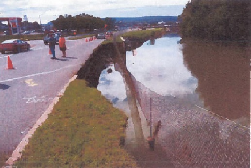
Looking south; the washed away wall sat 1m to the right of the fence

Looking North-East once river level lowered; the area to the left of the wall is what was washed-out (30m of wall).
The list of issues we’ve had is endless; the primary headlines are as follows:
– Unforeseen ground conditions. The biggest issue to date – who would have guessed??
- The temp shoring plan was designed by Larson’s group and hinged on tie-ing into an existing sheet pile on the north end and into the existing concrete wall on the south. Of course, as luck would have it, despite us supplying drawings that showed a sheet pile, there hasn’t been one found to date. As such, the excavation on the north end has had to cease at 5ft until a solution is devised – initial discussions with the designers suggest trying to minimise cost and time by using some of their H-piles they have in their yard and slotting in timber lagging between them. Of course there will be an REA submitted by the prime for lost hours and unforeseen ground conditions (USACE has to approve any new design iot prevent Heath Robinson work…and the approval is allowed to take 30 days!). This will be heated negotiation – from our standpoint, though the drawings were wrong, we did not dictate the shoring design of tieing into the sheet pile so the risk of it being there was borne by the designer. The other issue resulting from the lack of sheetpile is how the actual wall will now end, as we had designed it to tie into the sheet pile. After much debate, we agreed that if a sheet pile was there it wouldn’t do much anyway to cope with an extreme flood event as seen in 2011. In addition, we are fully conscious that this design is extreme overkill and forced onto us by the Dept of Transport – we would have been content to leave the remedial solution of rock armour fill and be done with it. Thus the wall will end abruptly but be surrounded by rock armour.
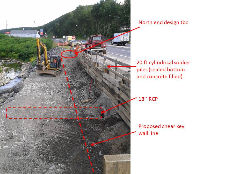
Looking North, standing on existing wall
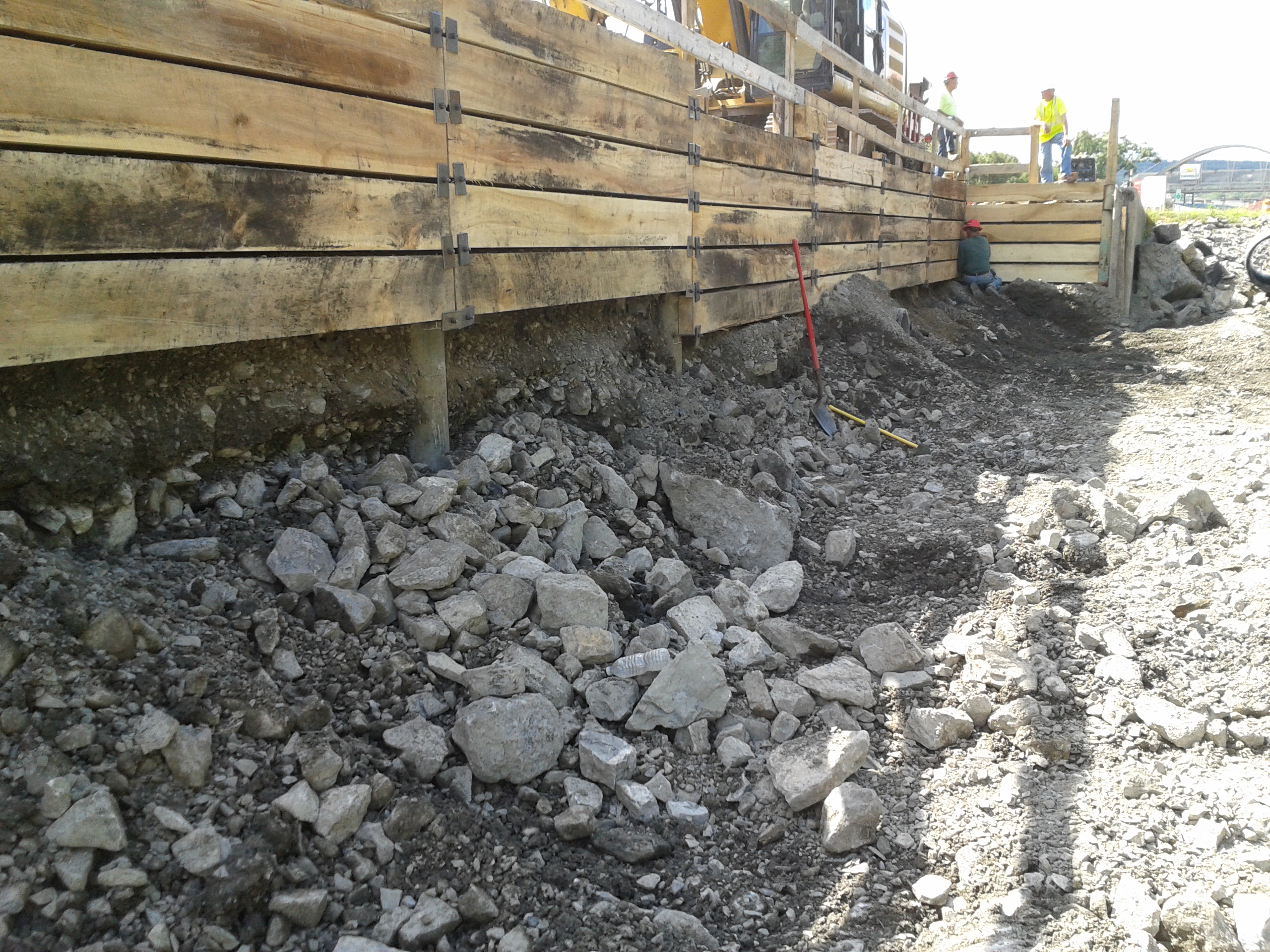
Looking south, excavation in 5ft lifts before lagging and welded attachments installed
- The geo-analysis and boreholes indicated the necessity for drilling through ‘rock’ (betw 8-10ft) in order to gain their sample to 22 ft. That therefore pushed the shoring design immediately away from sheet piles to the present circular tubes with welded bolts and plates and timber lagging. To date, I can count on one hand the amount of ‘rocks’ (>30cm) that have been excavated – normally parts of broken up concrete wall used as emergency fill; the remainder is 95% gravels – everyone is therefore asking the question as to what happened with the borehole samples (3 taken; 1 every 10m), especially as the shoring redesign was one fo teh main causes of several months of delay.
- The damaged concrete wall is now starting to be unearthed – we are unsure how much is there but I estimate at least an 18ft length (x 2ft width) at present. This will incur removal costs that have not been agreed upon as yet as it was guess work as to how much we would find…additional homework with answering RFPs.
- The 18inch reinf concrete pipe that runs perpendicular through the site taking runoff from the road to the river was initially decided to be dealt with by propping it up. Upon excavating down to it, it is actually damaged so has been removed and temporarily replaced with a plastic pipe. This has actually expedited site work, but we will have to pay for a new one.
– QC and safety ability of the prime. The prime has used their own guy as the QC rep and the safety offr. That is fine…if he was actually capable. Every time I have been on site there have been issues. To be fair at the moment there is not a great deal to check QC wise, so errors are pretty obvious. Annoying that I have to pick them up which results in disappointed Dad type chats…to a 50+ yr old! Somewhat aggravating as well that every question I ask, his comeback is: ”Let me ask the sub”! (the sub is essentially running the show!). Another classic was my question on D+2 – ‘where’s the E&S control’ (a pre-req for any constr); reply: ‘there isn’t any’! Needless to say that was the wrong answer; upon me going through E&S plan which he submitted to USACE I then asked where the Inlet protection was (i.e. filter bags attached to drain grillages) to which his response was: ‘What’s inlet protection?’…queue more disappointed Dad expressions, turn the page and show him the drawings!! As for safety, his inability and inaction has now become almost humorous – taking photos of welding (with welder and assistant not wearing eye pro!), workers not wearing high vis (in a heavily trafficked zone), standing right next to an area that has caved in behind the shoring and not thinking to do anything about it. Sadly, today I’ve been writing up an assasination on him upon request of the USACE area engineer who will use it as additional arsenal when chatting with the prime’s CEO and scoring their performance on the gov database. These nuggets are but just a few of his errors; he takes great photos though!
– Specs, drawings and standards…who wins? Well, of course standards do, then specs and drawings. The ‘as-built’ drawings (built in the ’70s) show joint spacings at 30ft intervals. As a result, the contractor has planned their formwork, rebar etc for such spacings under the pretense that the wall is to be built ‘as-built’ (total wall distance is 90ft). However, they have now seen that our specs say that joint spacings should be a maximum of 24ft, and the designers drawings show 20ft. Our answer to their obvious clarification RFI was that backed up by ACI and ASTM – a max of 24ft for a gravity walls. Queue – delays, rework, REAs, but again our standpoint is that construction must be done by specs unless superseded by standards – both of which coincide; we cannot be blamed or pay-out for errors resulting from using as-built drawings that were not built to today’s specs.
– Means and methods. As the government’s (client’s) representative we cannot dictate means and methods; this is quite useful at times for keeping one’s hands clean of risk, however I find it exceptionally frustrating when seeing things on site that can be expedited with a bit more planning and forethought, enabling concurrency of work. The QC manager however, though not particularly capable, is quite receptive to my ‘suggestions’ or ‘if I was to do it, then …’. A potentially major problem has however cropped up as a result of not knowing the means and methods when approving plans in piece meal. I have grave concerns that there is no sediment control on the most obvious largest issue – the excavation; thankfully the plant op is pretty handy so debris has been minimal if not nil, but all it will take is one storm and tornado and the pristine protected trout stream will become but a cloud..and the Dept of Environment will be throwing down a rather hefty fine…on the contractor mind, not us. Just because we approved the drawings does not absolve the contractor of responsibility or risk; our rational for approval was that the dewatering diversion dyke would also act as a sedimentation barrier hence we approved it…the diversion dyke is part of the dewatering plan which still hasn’t been approved yet for a variety of fairly minor issues, and has been held up by the QC manager for a week having mislaid its location in the approval chain on the bespoke USACE IT system that we use for communicating drawings, specs, RFI, REAs, submittals, payments etc.
In other news, the family headed out on a long weekend roadtrip through Pennsylvania into New York state, stopping off for one night at Finger Lakes renown for its countless wineries, then up to Niagara Falls – amazing experience, and well worth the miles! 

Understanding the risk in depressurisation well design
Blomfield Box Depressurisation Design.
Situation General. A review of the ground water monitoring was carried out earlier this month by the design authority (Mott McDonald) following concerns raised over the effectiveness of the current and the future depressurisation designs proposed by the primary contractor (Laing O’Rourke). The design authority highlighted its concerns over the proposed equipment and methods to be used to depressurise the sand and silt layers within the Lambeth Group of soils, on which London and much of the South East of the UK based.
Ground Investigation. There wasn’t one. Prior to ground works commencing on site the site was occupied by a building. The handover of the site was delayed. On the handover of site piling works commenced and no site specific ground investigation was completed, considered to be a luxury rather than necessity given the delays already against the programme and the potential financial implications of further programme delays. Despite the lack of a ground investigation the ground was assessed and has subsequently been proven during the excavation to follow the form typical for London Clay overlying the Lambeth Group of soils.
Engineering Risk .In the case of C502, the engineering risk is not asses to be the ingress of water to the excavation but the risk is due to the high pore pressure within the soil increasing the risk of base heave at the base of the excavation and shear failure of the exposed soil between the contiguous pile wall. In order to design against this risk the requirement is reduce the pore water pressure in order to increase the effective stress and thus the strength of the soil at the base of the excavation. Whereas water ingress is a property of a high permeability soil, high pore water pressure is a result of low permeability soil and as such the two conditions require different well designs to address the riskAdditional risks are identified as programme delays whilst works are halted pending the approval and implementation of an appropriate depressurisation system.
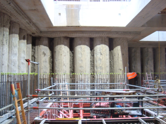
Contiguous pile wall with gaps exposing soil.
Current Depressurisation. The C502 contract and site (Liverpool Street) is in close proximity to the running tunnels being constructed adjacent and beneath the C502 site by the C510 contract. The nature of tunnelling has required C510 to have carried out depressurisation of the ground and since Aug 2013 C510 have been pumping at a rate of 300 to 600 l/hour from a system of ejector well points. The well points have been located in the sand / silt horizons identified during the C510 ground investigation. The ground investigation had shown that the pore water pressure was above the accepted levels specified by Crossrail. Following pumping by C510 the pore water pressure was demonstrated to have been reduced through the monitoring of a network of piezometors. In contrast C502 had adopted a deep large diameter well system with submersible pumps that are situated beneath the sand and silt layers within the Lambeth group of soils and have only achieved 100 to 200 per day. The two concerns that have been raised are:
1. C502 does not appear to have taken into account the effect of the depressurisation effect of the C510 ejector pump system in artificially lowering the pore water pressure. On completion of the running tunnels parallel to the C502 site, C502 will no longer be able to rely on the effects of C510 pumping.
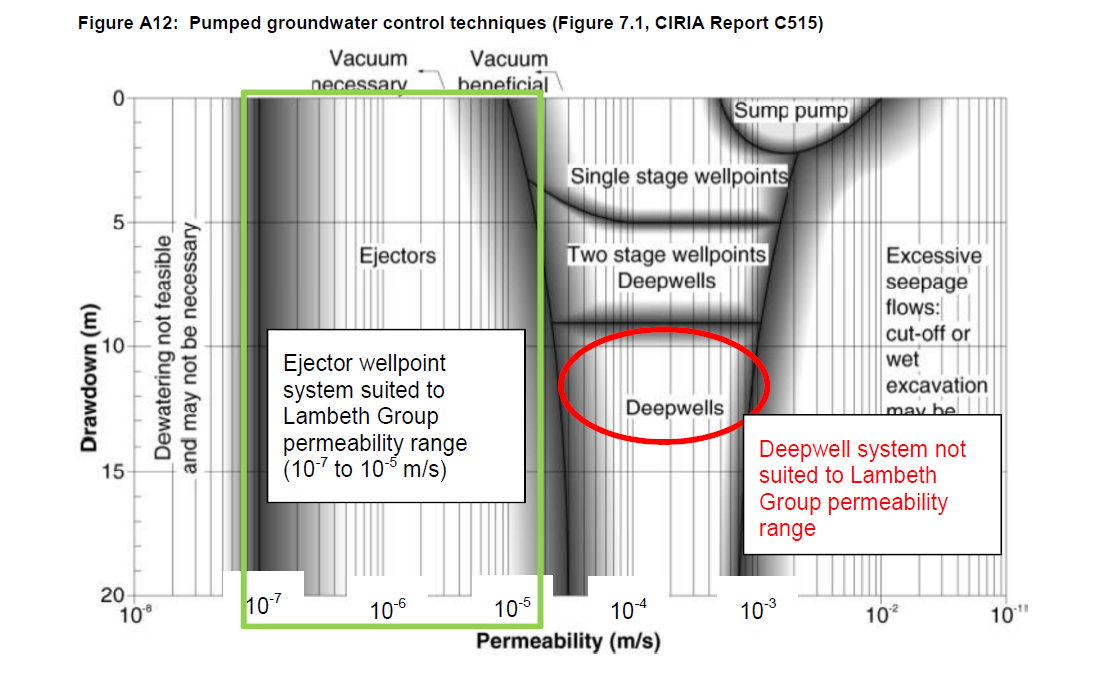
2. The use of submersible pumps within the Lambeth group of soils will not be efficient enough in lowering the pore water pressure to within the acceptable levels due to the low permeability of the sands and silts.
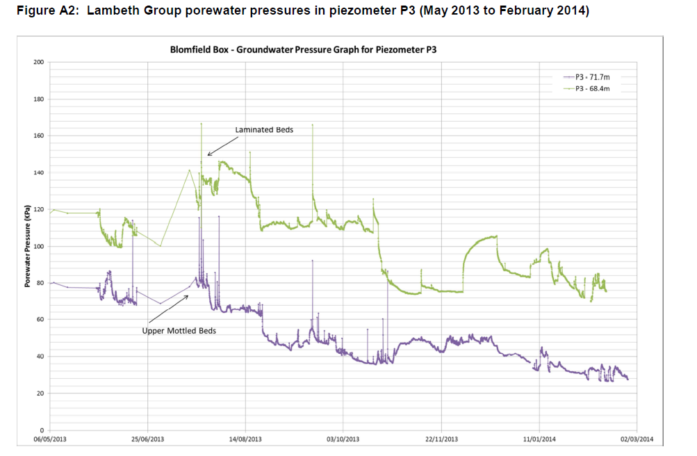
In the case of C502, I have assessed that the current depressurisation system that has been employed is not appropriate for addressing the actual risk posed to the project. The above graph clearly shows the impact of the c510 ejector pumps on the porewater pressure with a steady decline in the pressure, althoug it still remains above the Amber levels set by Crossrail. Over the period of Dec 13 C510 stopped pumping during a pause in works. Over this period C502 continued to pump however the porewater pressure rapidly rose within the laminated beds. Then steadily reduced once C510 recommenced pumping, but still remaining aboe the amber levels. This is clear evidence that the current well design is insufficient to address the risk of high porewater pressure.
Well Design. Although further research is required to understand the details of the plethora of different well systems available currently, it is important to ensure that the correct system is employed to address the identified risk. The systems can loosely be categorised as Deep Well system or Vacuum assisted systems
Vacuum Assisted Wells. The basic principle of a vacuum system is that by generating a vacuum within the well an area of low pressure is formed which in turn lowers the porewater pressure. These systems are best employed in soils of low permeability in which pore water does not freely flow and must be drawn out of the soil to lower the overall porewater pressure.
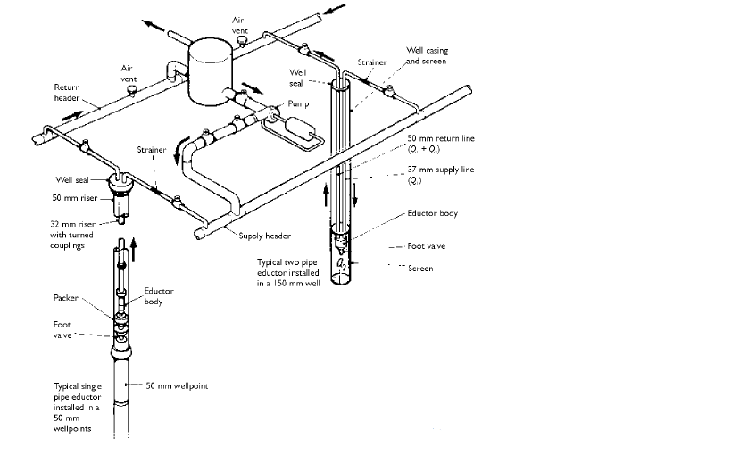
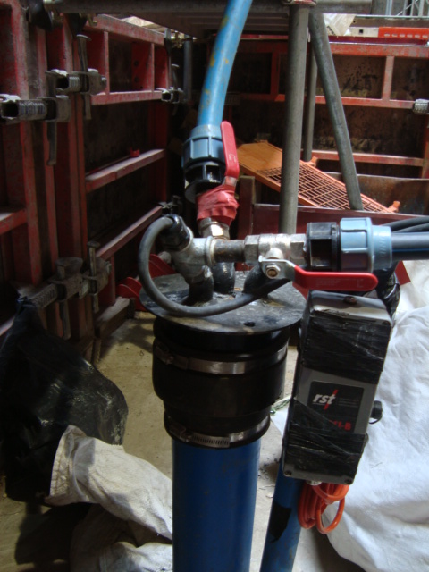

Diagram showing layout of vacuum well system & Onsite Vacuum well
Submersible Pump Wells. A submersible large diameter well relies on a high permeability soil to create an area of low pressure and to establish a hydraulic gradient. These well systems are suited to high water flow and are used to address the risk of ground water ingress to a site.
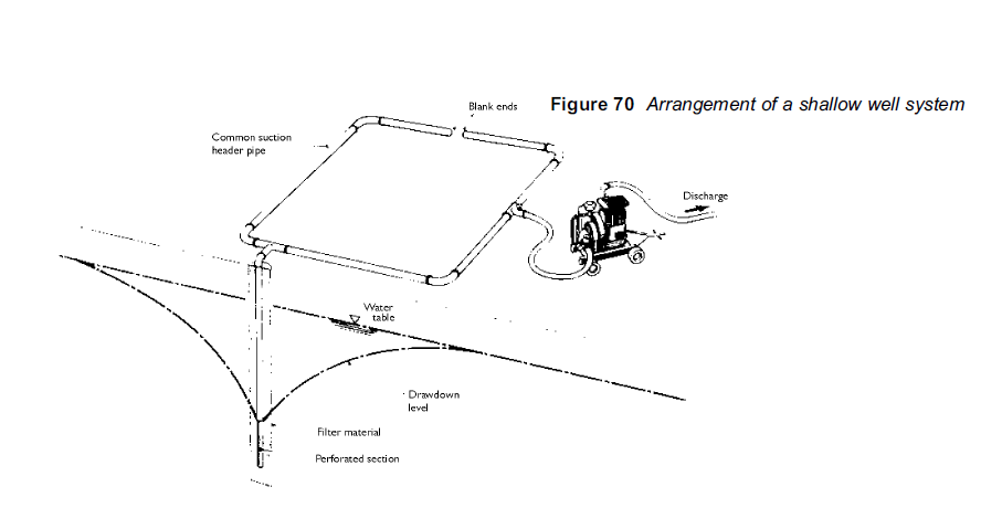
Diagram showing submersible well system
Conclusion The publication of a report from Crossrail that has required C502 to revise their depressurisation system has caused a level of disagreement on site with many of the engineers seemingly missing what the actual risk. There appears to be a common misconception amongst the site engineers that high volumes of ground water ar symptomatic of high pore water pressure and the risk of base heave. As a result many do not share the Crossrail concerns of high pore pressure posing the risk of base heave and are appose to utilising a vacuum system that will delay the programme and cost ultimately more to install and run.
I can hear Johns words once again” never assume anyone really knows what they are talking about”
Red Card Moments – Part 2
Following the PFA ambush of last week, BFK have found themselves backpedalling to find a solution. A contract wide issue that is still being discussed by senior management up in the ‘Deathstar’; however, down at Fisher St, we critically need a self compacting mix trialled and approved before the middle of next month, should the PFA risk manifest itself. So with an empty chair where the materials manager used to sit, and our Materials Tech jumping ship, we were down to a cast of one….
Requirements
The client’s materials and workmanship specification for cast in situ dictates mix design and trial requirements as follows:
Temperature: 2 key points:
- At the time of deposition of the concrete, shall be in the range 5 degrees and 30 degrees. (A planning figure for expected heat gain is approx 10 degrees per 100kg of cement per m^3. Our mix contains 270kg per m^3, and therefore a 27degree heat gain on a 30 degree ambient temp would remain in spec because….
- The upper temperature limit of the placed concrete should not exceed 60 degrees C. Designed to minimise the risk of thermal cracking.
Testing. During trial mixtures need to demostrate results for:
- Compressive Strength
- Consistence
- OvenDry density
- Fresh Density
- Bleed
- Segregation
Testing is conducted on at least three specimens from at least three batches, andis in accordance with Annex A of BS EN 206-1:2000 and is a thrilling good read!
Temperature Testing
In order to demostrate the temperature gain and the max temp value, a 1m^3 sample is poured into a ‘coffin’. This coffin is installed with thermocouples which will measure the core temp, surface temp and the ambient temp during curing. This setup is shown below.

1m^3 of self compacting mix. Note green thermocouple wiring
Temperatures will be recorded by the data logger at a rate of every 30mins for two weeks.

Ruggedised data logger will record data over a two week period
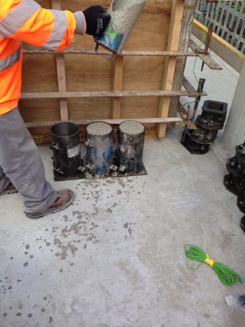
Concrete Strength
Requirement:
In Situ Concrete strength requirements, C8/10(12hrs), C32/40(28 days)
Test cubes will be crushed at the following frequency, in accordance with the specification. 1 x 12hr, 1 x 24 hr, 3 x 7 day, 3 x 28 day, 3 x 56 day. This frequency will give indicative early age strength gain for reassurance, followed by the criteria test at 28days. This allows concurrent activity…I have written the Materials Compliance report for approval by the client on the basis of the early age stregth gain;it has been approved, on the caveat that it does gain the 28day strength. If this criteria is not met at 28days, the 56 day cubes will be crushed, and the results will be demostrated to the client for approval.
Consistence
A slump/flow test is conducted in accordance with BS EN 12350-2. A critical feature of the self compacting mix in this instance is the workability. The location in the works dictates that the concrete pour would be difficult/unsafe to effectively vibrate into position, and thus a flow to allow movement into these areas is an imperative.
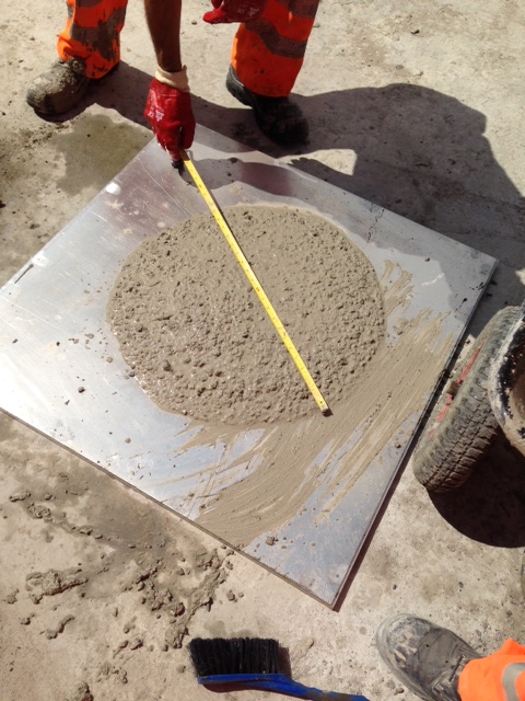
Note sample has been allowed to reach its full diameter at measurement.
The specification requires samples to acheive a flow result of 490mm – 650mm. This sample achieve and average measurement of 550mm. Additonally, bleed was visually inspected on this sample and considered to be the within limits
Segregation
Three cylinders of 150mm diameter and 300mm height were cast for the batch. The cylinders are then sliced into 6 sections of equal thickness. The mass of each slice is then measured and the density calculated to determine density variation throughout top to bottom of the sample. The average variation from the top to bottom of the cylinder shall not be greater than 10% of the mean density of the concrete

Segregation in the sample will be demostrated by aggregate gradually moving to the bottom of the cylinder, thus increasing the average density to the bottom.
So with help from the concrete supplier, we’ve designed and tested a self compacting concrete mix, that thus far is performing as required by the specification. If it continues this way, my mix design may well be used throughout cast secondary lining throughout the western tunnels. Terrifying….
BUT…before there is a mass protest/retirement at PEW!
Just as I was about to publish this, I’ve just received a slightly panicked email. Due to concrete suppliers switching to GGBS after the PFA shortage, and a problem with the discharging of ships at the Port of Entry at Tilbury, UK GGBS stocks are currently at 30%! Brilliant…
It’s DO heaven.
The project has evolved in recent weeks with several variation orders taking the total value of the work from £63m to £121.5m. These additions include £6.5m worth of variations to the initial contract covering a number of smaller embellishments and alterations, £2.5 for a RC slab in the coal yard adjacent to the site, £2m for a radial arm stacking conveyor also for the coal yard and £47m for IRFT 2. IRFT 2 is a sizeable extension to the facilities currently under construction including 4 more RC Biomass storage silos, an extension to the existing conveyor system and another rail load out facility and accompanying silo. The work on the coal yard slab and the piling for IRFT 2 has started and extends the duration of the whole contract from October 14 until July 15. Part of the site (phase 1) was commissioned on 22 May 14 and now fully operates from the lorry load in area to the rail load out facility. This allows large Biomass container ships to dock at the port, where HGVs can be loaded directly and then the pellets can be transferred to the rail load out point for onward movement to Drax power station. Part of this commissioning included testing and individually commissioning all of the electrical, safety, dust and fire suppression systems and the establishment of an operations team to run the facility. To date over 13000t of wood pellet have been loaded and transported to Drax power station. The completion date for IRFT 1 phase 2 (the rest of the site) is currently delayed by 22 working days / 30 calendar days and as such performance testing of the plant is scheduled to begin on 13 October 2014, the site is running a 12 hour day / 7 day week to maintain progress. The progress for IRFT 2 is currently on schedule with work having started on 09 June 14.
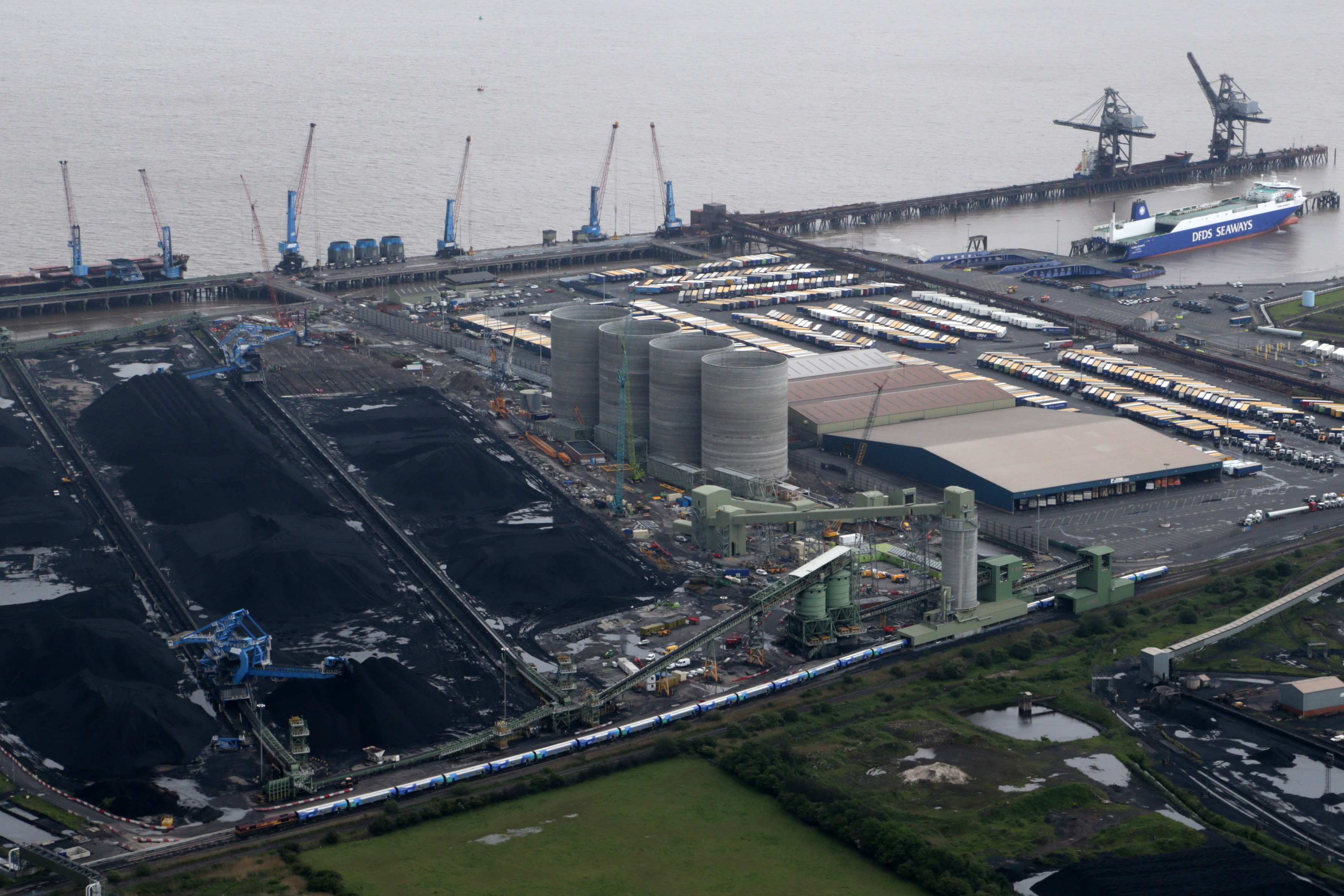
The current site.
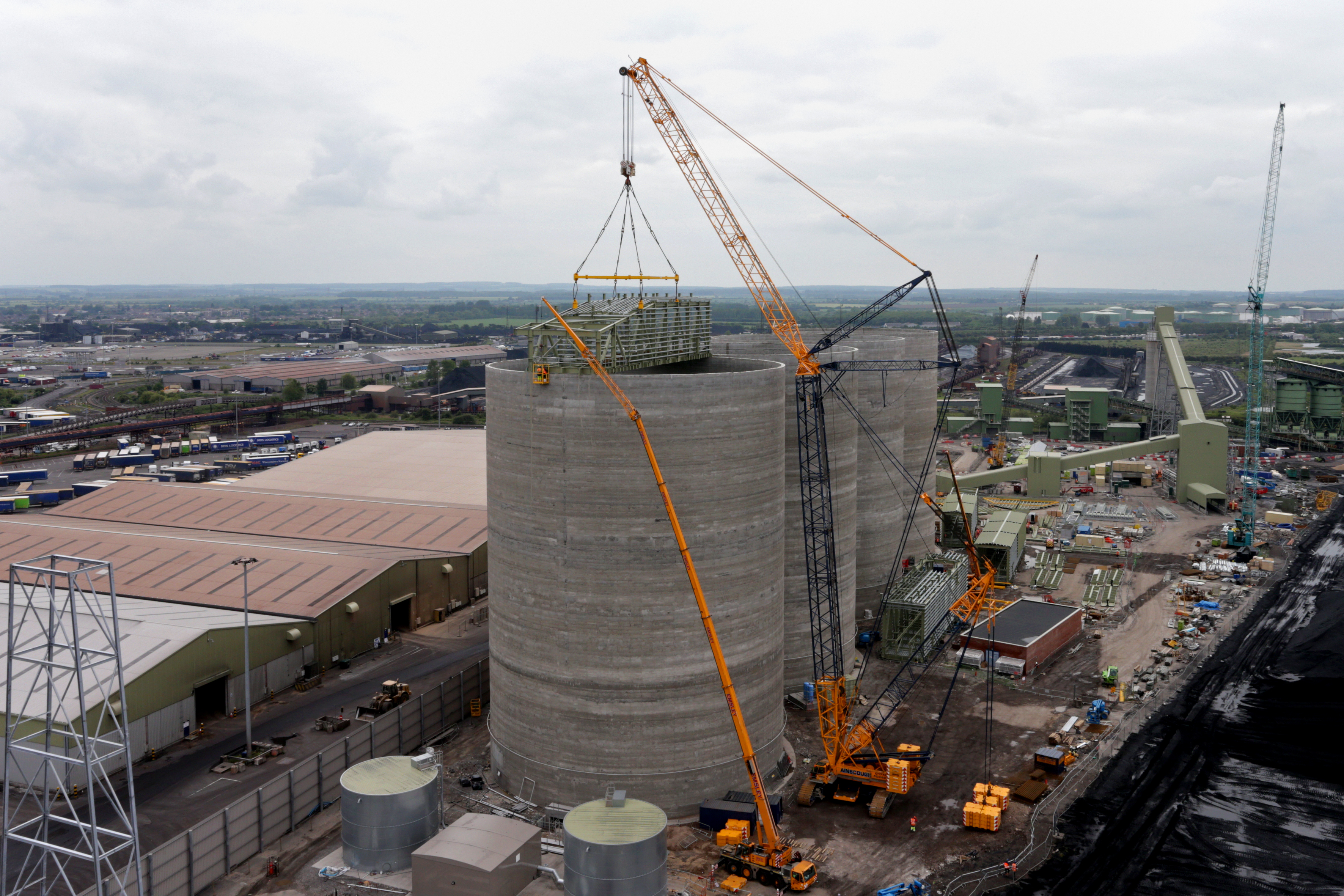
Roof truss lifted onto silo 1.
My part in this, the dwarf wall, continues although at a slower pace due to increased pours for the roof slabs to cap the IRFT 1 silos, but I now have other projects to keep me busy in my section of works.
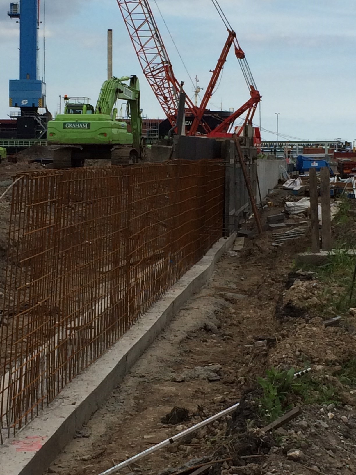
The Dwarf Wall continues.
These additional duties are allowing me to knock off quite a few of the harder to achieve DO’s.
I am now also responsible for the excavating and placing of several 100m’s of HV ducting and a water deluge main for the fire suppression system of the previously constructed Conveyor 620 system. Whilst technically simple the mountain of paperwork I have had to complete for each section has allowed me to gain some purchase working towards the difficult DO’s. The ducting effectively runs between the various substations, old and new that border my section of works, hence the responsibility, and cross a significant number of existing live and non-live services.
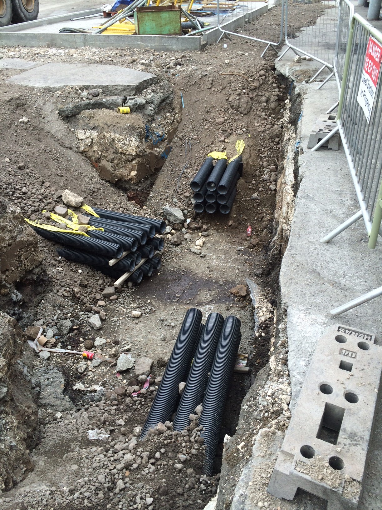
Ducting runs into a future manhole.
I have completed an overarching method statement and risk assessment for the task, breaking it down into individual sections or ducting runs between the existing and to be constructed manholes. This includes the procedures for working parallel to and crossing over existing services including live HV cables; a detailed traffic management plan due to several road closures (not popular with the client, ABP, running a very busy port) and the safety precautions for working in deep excavations.
Prior to this I had to conduct an in-depth analysis utilising all the available drawings provided by the client, utility companies and a Graham commissioned GPR survey to pinpoint all the services. I then verified these findings with a CAT Scan survey having just completed the CAT and Genny course (one for the CPD record).
I have then been briefing the subcontractors outlining the programme of works, the methodology, the risk mitigation procedures and any residual risk before getting them to sign up prior to sending all the data through to the client for their final approval.
All of this activity has allowed me to progress towards a number of DO’s (B2, C1, D1, E2).
I have also volunteered to mentor a year-long placement student who started in earnest last week. This additional responsibility has allowed me to consolidate my experiences to date and share MY extensive knowledge. I felt it necessary to step off on the right foot so I immediately grilled him for definition of undrained shear strength to gauge the depth of HIS knowledge…..there was a long pause…..an awkward shuffling of the feet…..a look to the left and the right for moral support…..and then came the McGuirk 1000yard stare…..he didn’t know, can you believe it?? I couldn’t. What are they being taught at uni these days? I gesticulated wildly, banged the desk and was about to unleash my pavlovian response when I got distracted by a chocolate digestive. I’m surprised I’m still talking to this simpleton but I’ll tough it out for now as it is proving another excellent opportunity to knock off some DO’s (C3, D1 and 2 and E4)!
I should have the ducts finished by the end of this week, the wall by the following week prior to my summer leave. On my return I am likely to be given an independent command……my own bespoke site about a mile down the road to build a sub-station all by myself! I have also requested to be part of IRFT 2 rail load out silo slip forming team to ensure that I get the maximum exposure to as many different construction processes as possible. No real reflections this time but plenty of DO progress.
The Network Rail Road not so grand opening
Well the Network Rail Road was meant to open on the 26th Apr but due to various issues that I will go into a bit later that did not happen and only a small portion was opened. Grand opening number two was the 30th Jun and I hoped to write a great blog with pictures of us all celebrating a milestone, but 2 weeks later we are still not finished. So why has such a simple task of building an access road been so difficult I hear you all ask. Let me explain…
Here is what was explained to me back in Feb:
Mission: To construct the Network Rail Access Road once all services have been installed.
Concept of Operations
Intent: To open the Network Rail Road for construction traffic.
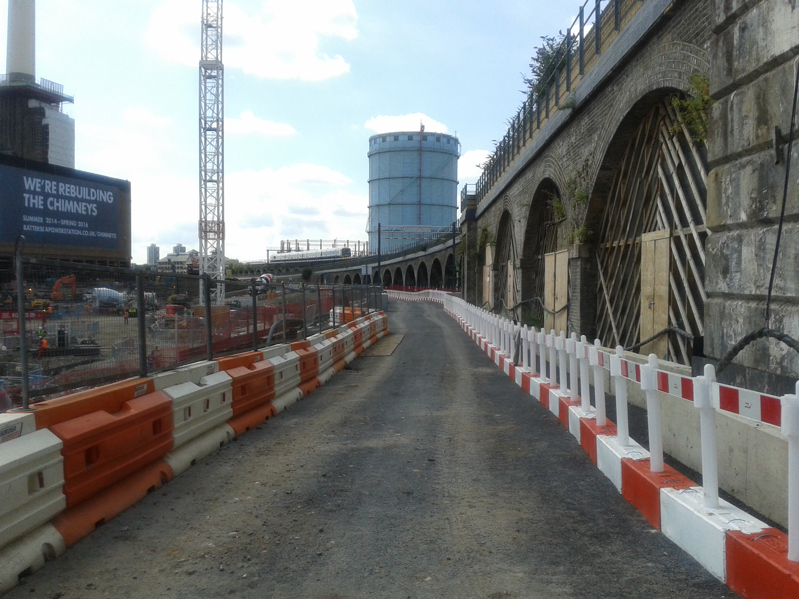
Scheme of Manoeuvre: Install deep foul drainage, then surface water drainage, followed by shallow services such as HV, potable water, rising main and comms, install the final road build up and surface. The diagram below highlights the main locations with the road running along the left side of the picture.

Main Effort: To open the road for construction traffic use by 26 Apr.
Constraints: The road is bounded by the Network Rail arches (the main line into Victoria) in the West, the sheet pile cofferdam of the basement in the East and the River Wall to the North.
Again it all sounded pretty straightforward, the sub-contractor had a realistic looking programme and they had already made good headway on part of the deep drainage when I turned up in Feb. So what has gone wrong?
Issue 1. The major problem has been a temporary works issue that arose from a contractual decision. The capping beam of the sheet pile cofferdam for the basement was originally in the groundworks sub-contractors (O’Keefe) package but as a cost saving effort it was taken out and put into the concrete frame sub-contractors scope (Byrne Brothers). With the contractual team happy in the thought that they had saved a few pennies the construction team carried on building. It then became apparent at the start of March that we kind of needed the capping beam to hold up the road that we were building and now the contractor had changed it wasn’t going to be built for a few more months.
Solution: To cut a long story short we ended up getting O’Keefe to design a temporary retaining wall for the road to allow the construction of the road and the formation of the capping beam. This was in the form of a king post wall made from UCs and trench sheeting and pre-cast L-sections (my idea stolen from John’s retaining wall lectures!). The pre-cast sections were suitable for south of the pumping station where they would fit in with the services but not for the north. These were installed quite quickly and the south section of road was opened on the 26th Apr as planned. The king post wall installation added another 6 weeks and probably 10’s of thousands of pounds to the cost of the groundworks package.
Issue 2: The road level was designed to give enough cover for the shallowest main service which was the rising main. The Project Director wanted as many of the smaller branch connections to supply the bridge arches (mostly clay drainage pipes) in as possible prior to the surfacing of the road. Once constructed it was apparent that these were not going to have enough cover under the road.
Solution: Ramp over them, chuck some trench plates over the top and hope they don’t get trashed!
Issue 3: Nobody had actually designed the northern section of the road. The design engineers Buro Happold had helped with the suggested temporary levels of the main part of the road and this was signed off by the Carillion Temp Works Designer (TWD) (who doesn’t work on site or solely on this project).
Solution: The Carillion Project Manager suggested an idea to the TWD, he said no, we amended the design to his comments, the Environment Agency Flood Defence Consent people said yes so we cracked on and built it.
Issue 4: On the grand opening take 2 on the 30th Jun the Project Director walked the road with Byrne Brothers (who will be the main user) and they deemed it was not fit for purpose. Despite being built to the designs it was both not wide enough (for 2 way traffic) and too wide (not enough room to construct the capping beam). They had intended to have unloading areas for the tower cranes and vehicles passing at numerous points along the road.
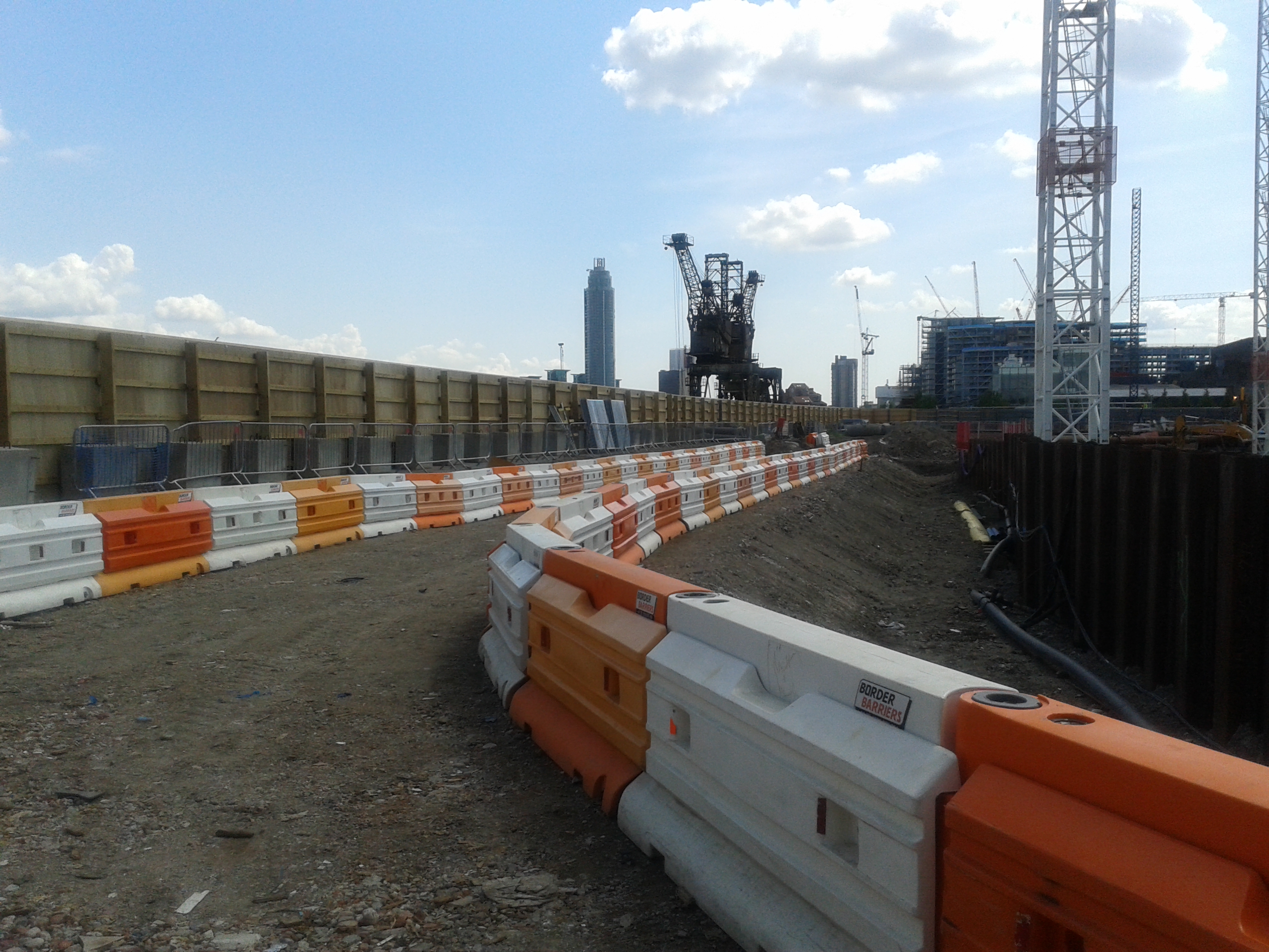
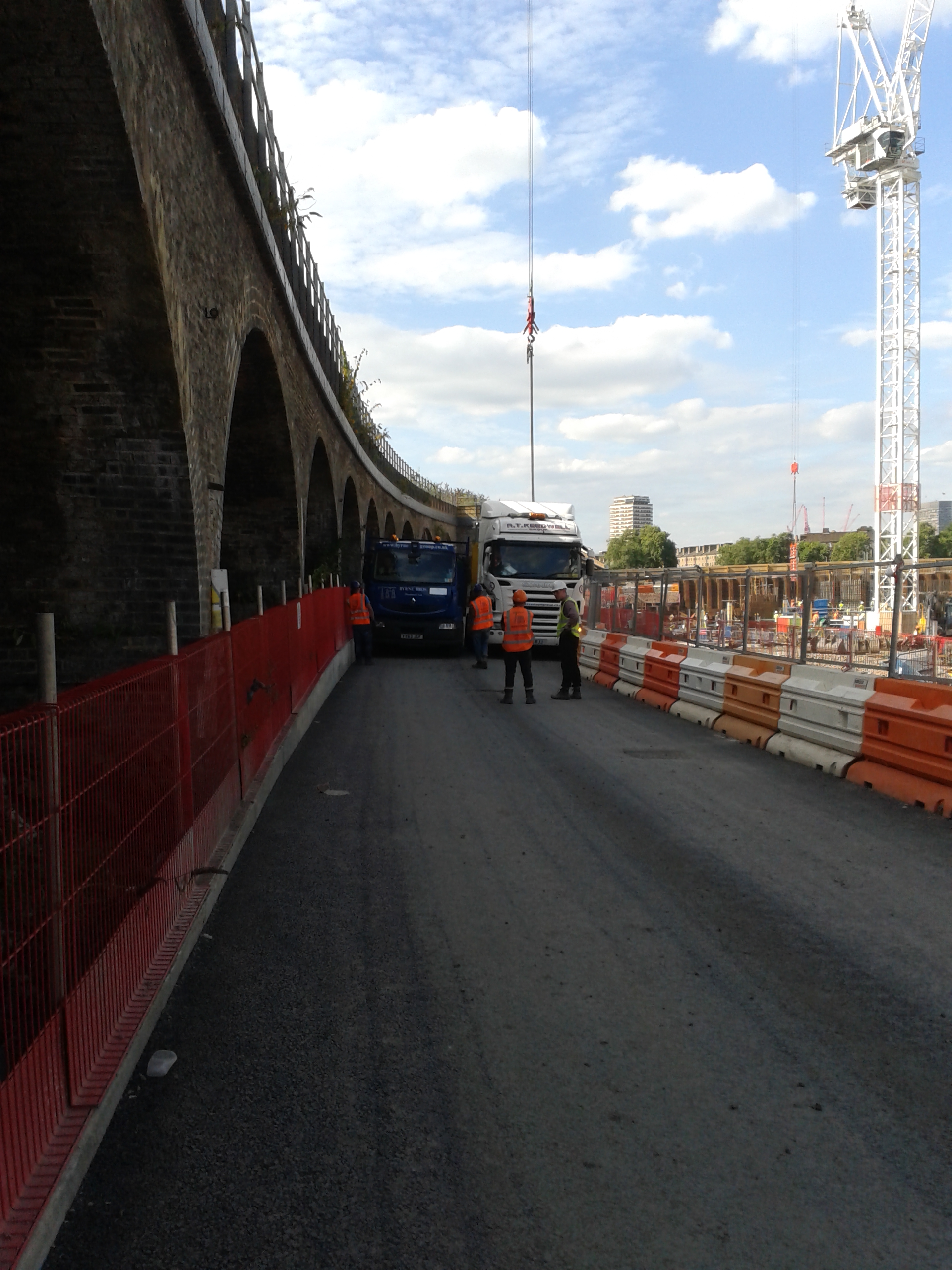
Solution: Remove the pedestrian walkway, push the vehicle barriers closer to the edge, make it wider in the north (ignoring the design of one TWD and using another ones design that allowed for more surcharge on the sheet piles) and hold your breath and close your eyes as your truck squeezes past the artic lorry:
So what have I learnt from this rather frustrating and costly ordeal?
Communication is key. The section engineer in charge of Byrne Brothers is too busy to attend construction team meetings and therefore has never communicated the actual intended use of the road. If the sub-contractor and I were told that they intended to unload vehicles then we could have flagged up the width issue months ago. We could have also planned the barrier system to ensure the widths were adequate rather than build everything then strip it out again.
Plans should be war gamed. The decision to remove the capping beam installation from the groundworks package has significantly affected the road construction. Changes to the plan should be communicated and discussed with everyone that it may affect so problems can be identified early.
Have a clear reporting chain. Too many people have been involved in making rushed and ill-informed decisions with regards to the road and nobody has been the single point of contact in charge of it’s construction. I was given the responsibility of monitoring the installation but it became apparent that I had not be told the end user’s actual requirements. Decisions were made by the Construction Manager that then didn’t work on site and he should have delegated the responsibility of designing a solution to me or one of the other section engineers who work frequently on the site. We could then brief potential solutions to allow the senior management to make an informed decision.
Well tomorrow I get to draw up the second sketch of remedial works and hopefully some white line loading bays will get painted on the road on Sat and I can have the grand opening take 3 on Mon. In the mean time I will be trying to help design an elevated footpath to help widen the road some more! I think a more detailed (and slightly less sarcastic) analysis of these technical and managerial issues associated with the Network Rail Road could be the next TMR topic for me.
Engineering is not the only risk.
Situation.
The northern wall of the Blomfield Box Superstructure runs parallel to the London Underground District line. A heavy duty fence had been erected to provide the required barrier between the two sites and to protect both personnel working on site and trains from construction activity. Concerns over safety and constructability of the current design of an insitu RC wall and aluminium rain screen cladding.
Build-ability: With the heavy duty hording in place there is no means to access the other side of any formwork to strike the formwork once the concrete has been poured. Left in place form work was looked at to overcome this issue but the issue of affixing the rain screen cladding would still be a problem.
H&S: In order to construct the rc wall and cladding access from the track side would be required to erect formwork and to fix the rain screen. Due to the live track this would only be achievable during engineering hours (0100-0500 daily) during which time the track is in places still live other than those sections that work is taking place.
Commercial: The closure of the line and works completed during engineering hours is very expensive with cost payable to both London Underground for line closure and in overtime for the Laing O’Rourke operatives. It would also have a knock on effect of additional labour cost as those working over night would not be available to work the next day shift, therefore additional operatives required to ensure the day work is not affected.
The proposed solution was to use a precast concrete cladding section that could be lowered into place and fixed from the inside to remove the problem of live track side working and to reduce the need to work in engineering hours. The requirement for the precast is as per the Project Managers Instruction below:
1 Change the cladding arrangement at Blomfield Box North Elevation from the current “aluminium rain
screen on RC/ Blockwork substrate”, to single skin Pre Cast concrete plank spanning vertically as per
a. Liaise with C138 – Peter Churton, and agree: 1) Loading; 2) Fixing restraint requirements; 3) Any
changes required to the concrete profiles; all to be subsequently recorded and agreed in an ICD.
b. Design, detail, manufacture and install cladding in such a manner that the works can be achieved
without the need for temporary access/disruptions to the railway face of the building.
c. The joints in the PC planks to be detailed with solid mortar/ grout infill with adjacent planks locked
together by interlocking rebar detail, generally as provisionally agreed with C138/ CRL during visit to
Explore this winter.
The issue that has now arisen is that the PMI was issued having not consulted all departments and has been to constraining in its direction and has resulted in a period of abortive works that have subsequently lead to compensation proceedings.
The new issues:
Non Structural: the precast wall is now to be a cladding/fascade and not a structural wall. This means all connections must not become load pathways and load the wall. As the superstructure will now be acting as canterlever and we have been told to assume a 20mm deflection the connections must be flexible enough to account for this.
Fixed grout connections: The connections have been stipulated as grouted. This has given us a number of issues: Firstly the grouting of joints means that there will be no flexibility in the joints, therefore the panels will need to be stacked on top of each other and that the 20mm deflection will need to be accounted for in the connection between the superstructure and the precast panel and not between the panels themselves. Secondly the purpose of using precast panels was to remove the requirement to access from the LU live track side. The use of grout to seal the connections still requires some form work to prevent the grout flowing out of the connection during pouring and then the form work would have to be struck from the track side.
Architecture and planning: the accepted precast drawings by the architects and the planners show the precast panels fixed externally to the superstructure. This however requires that the precast panels are fixed to the original rc wall location as there is no structural plinth directly at the base of the precast panels new location.
Heavy duty fence line: Having set off down a proposed method of affixing the precast panels to the superstructure and having though we had resolved the structural and architectural issues I thought I would just check the fence alignment. One survey and painful lesson in using AutoCad I discovered that the space between the heavy duty fence and the precast panels would only leave 40mm of space in which to manoeuvre the panels into place. Time spent in reconnaissance and all that….In during my investigation of the heavy duty fence line I raised concerns that should we proceed with installing any wall be it RC or Precast once fixed in place there would not be room between the electrical cable rails and the new wall to access the fence to allow for its removal. As a result the fence would become a permanent feature. This I knew to be unacceptable to LU.
M&E: The show stopper however has come in the form of permanent services. The original design of the services was hard against the RC wall. The new precast panels once fixed external to the superstructure would only leave 200mm gap. This presents a maintenance issue as the connections would have to be exposed in order to account for any deflection and would therefore require inspection and maintenance. Having raised this with Crossrail and that we would need alterations to the M&E it soon transpired that this was not possible without incurring huge redesign costs. IN addition the possibility to use access hatches through the M&E ducts to conduct future inspections and maintenance would also cause large commercial issue in the future. The ducting is to be used to provide ventilation to the shaft, station platform and running tunnels. Any interruption to the ventilation would result in the closure of the station. As a commercial business this requirement for periodic station closure to maintain the precast panel connections is not acceptable by Crossrail.
Conclusion:This fire and forget approach is becoming a bit of a theme on site with departments and individuals reacting to issues and concerns raised without fully working through the consequences. While in this case it was for us to resolve the issue the constraints placed on the changes allowed little room for manoeuvre. After all the design changes and arguments over the structural design of the panels and waterproof connections the elephant it the room turned out to be the heavy duty fencing. Originally proposed as a means to avoid live track side works the precast panels still require the fence to be removed and this can only be done live track side.
We are back to square one, the PMI has been retracted and we have been instructed to now propose a new solution or accept the original designs and the risk that are associated with this. The abortive works that have been completed have now been passed to the commercial team to proceed with compensation proceedings against Crossrail and all for a getting out of the office and fully understanding the situation on the ground. This episode harks back to John and his lessons on retaining walls in that the designs only show the wall in place but if temporary situation won’t allow you the path to the permanent state then you may need to rethink the permanent state. And a lesson from myself in that sometimes the temporary and permanent conditions must consider not only the engineering risk but also the commercial and other department risks.
The pace quickens
The last two weeks since returning from Tasmania have been rather hectic. It was nice of my site engineers to leave everything untouched so that it took the first week just to catch back up.
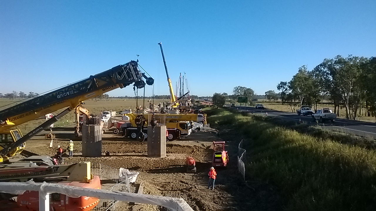
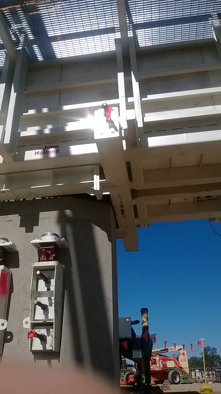
The Form, Reo, Pour process is now in full swing for the pilecap and column section of the substructure. There have been a few teething issues with the formwork, particularly where the pilecaps interact with the columns. This is now resolved and we’re pouring about 2 pilecaps and 2 sets of columns every week, with 2 headstocks soon to be added to that weekly tally. The 280t crane has also arrived on site and been commissioned, ready to lift the girders…if we ever get any.
The changes to the reinforcement in the headstock were finally approved after a meeting with the us (main contractor) the steelfixers (our subby), the clients rep (on site inspectors) and the designers (AECOM). We came to a workable option that satisfied our need for prefabrication and the designers need for torsional reinforcement. Though I still can’t understand their concern when we only needed to change a small section of bars. I did quiz them but got nothing back. I’ve also seen the cage successfully lowered into the bathtub (formwork) and the pour is planned for tomorrow.
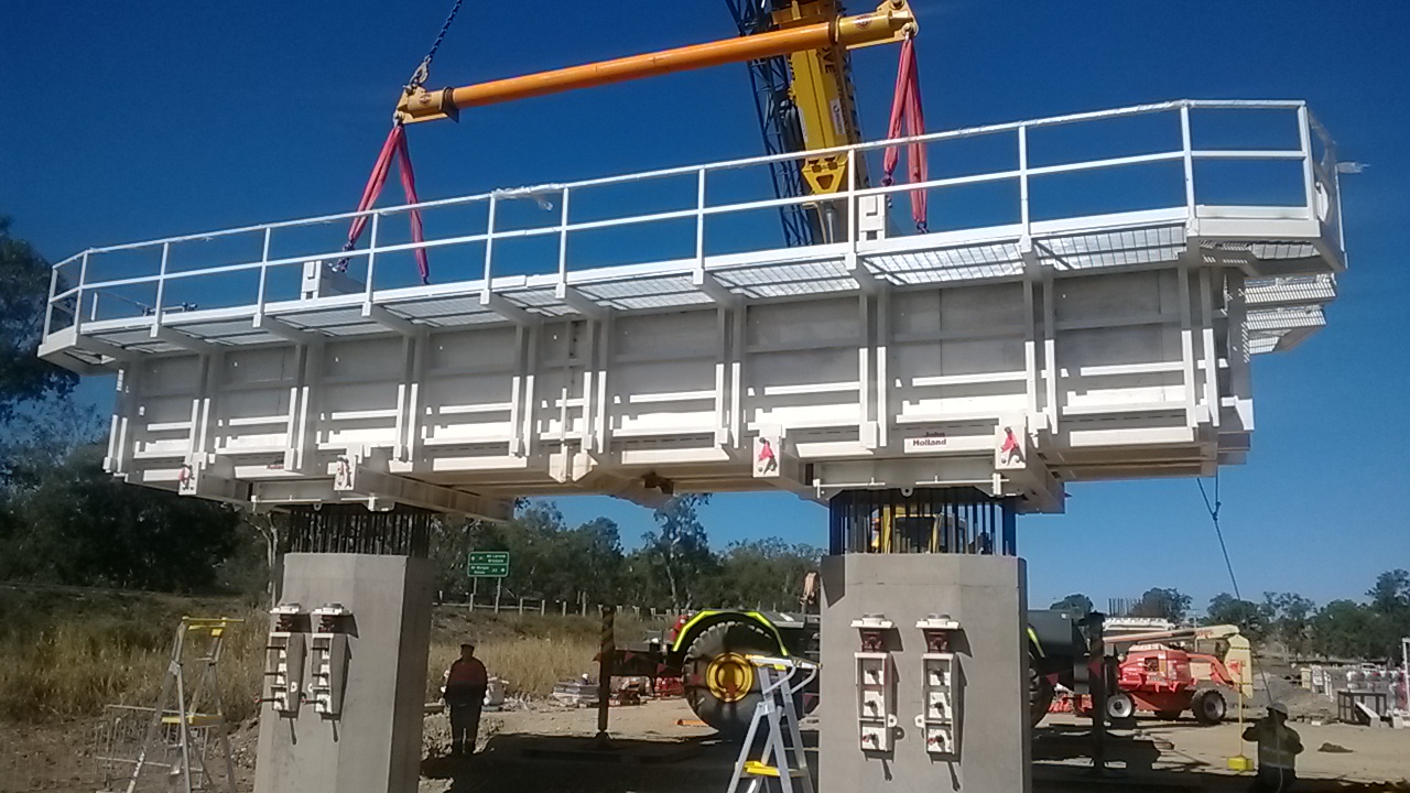
There have been issues up at the precast yard recently that I will probably cover in another blog, as the safety investigations are on going. As a bit of background john Holland have built their own precast yard for this project to make the 700 or so girders for the 2 bridges. These are 35m long prestressed pretentioned girders with a lot of strands in them (I’ll get more info in the following blog). The first incident was a prefabricated section of reinforcement for the girders toppling over. While no one was injured, due to the size of the cage and potential to harm this is being classed as a 1P incident (notifiable to the Aussie equivalent of the HSE). The second was during a girder pour 4 strand couplers failed while in tension. With 200KN on each strand this was really dangerous. I will get some of the photos of them smashing through some wooden boards and into the stressing trench wall. Again no one was injured as the controls were in place to stop this. I’ll get more details when I can. Without wanting to second guess the investigation the control appear to have been in place, and as they have let us continue work they must be pretty happy with the process and controls.
The piling crew has now kicked things up a gear and one rig managed to install 8 piles on its own yesterday, when they are only planned for installing 4. This might have a major impact on the supply of piles to keep the rigs busy. At this rate they will catch the casting program in 4 weeks time. To mitigate this the plan is to split the rigs and send one over to start bridge 2 early. All the piles on bridge 2 are spliced and this will slow the rig down considerably. It will also buy more time for me to prepare everything for the cofferdams that are needed for pier 1 and 2 in scrubby creek.
There have been a number of minor dramas and modifications to the headstock formwork to get it to the stage shown in the photos. The first drama was the project manager not approving the purchase order for the stressing jacks in time to get them on site! I’ve now had to go to VSL at short notice and get them here to fill the gap till I could get some kit here (as it happens I got a bargain on some kit from another JHG job that is coming to a close). Trying to rush through a short term subcontract has been a nightmare, mainly due to the terms and conditions that VSL work under. They only want to be liable for 5% of the contract value, but as the contract may only be a few thousand dollars this just isn’t acceptable – if their stressing fails the damage could be in the tens or hundreds of thousands of dollars. However, I’ve managed to get someone onto site though a bit of a loophole (but with the commercial managers blessing).

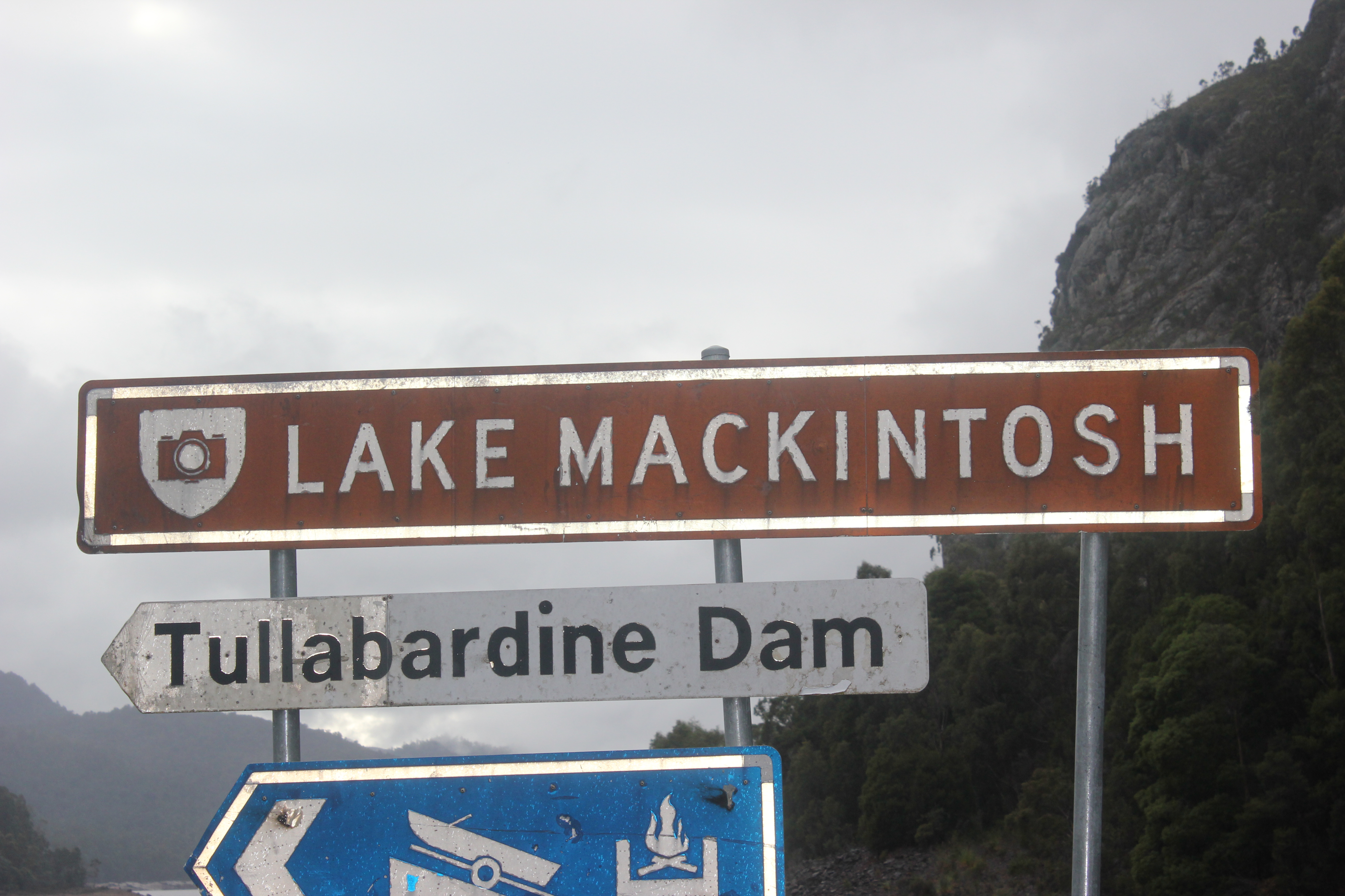
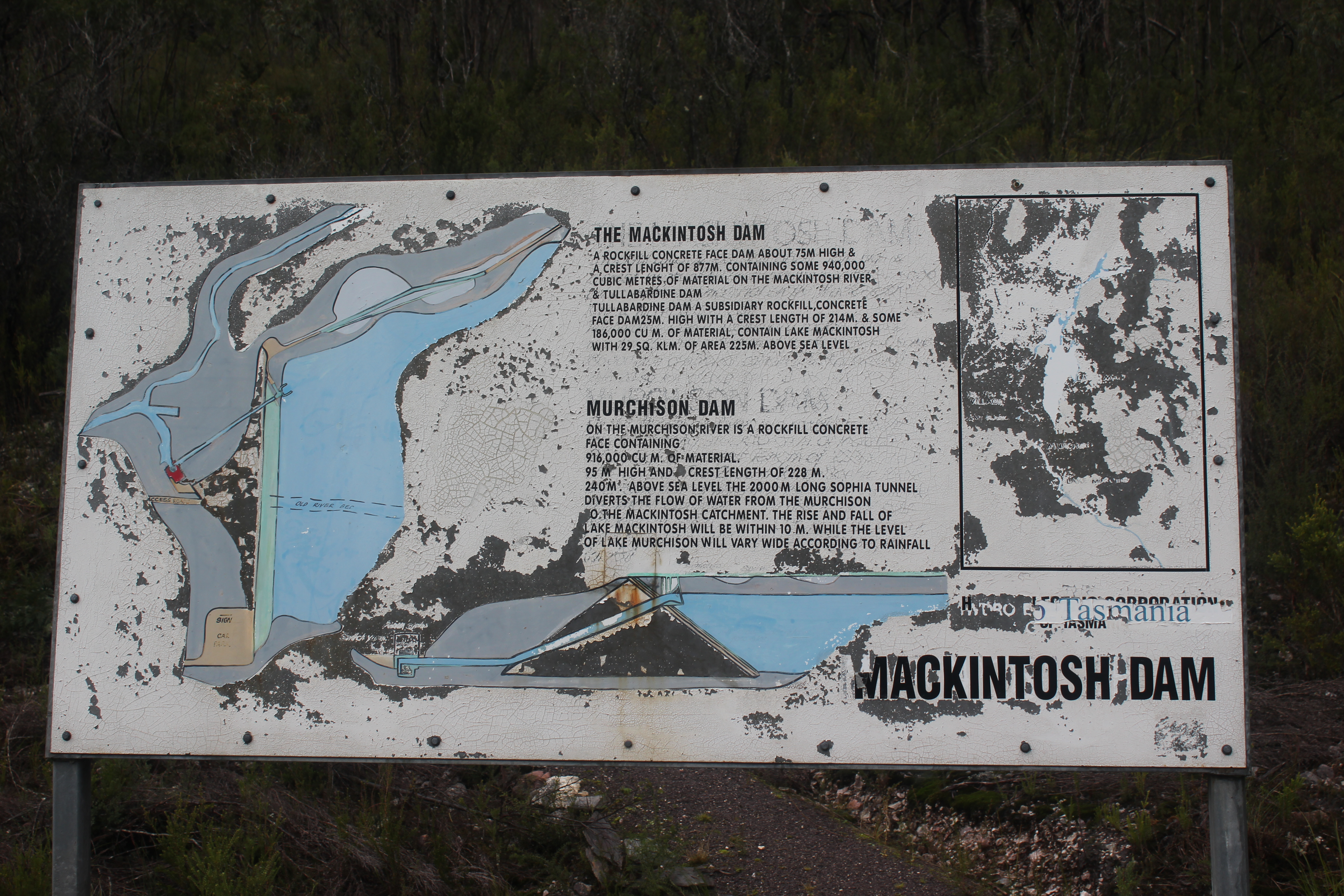
In other news I would thoroughly recommend Tasmania for a holiday – it was great, and they have even named a lake after me. Went and did the Gold Coast Half marathon with Ben and Sharna (though Ben managed to pick up an ITB injury that meant he had to withdraw, so he consoled himself with a few drinks).
When QC falls down
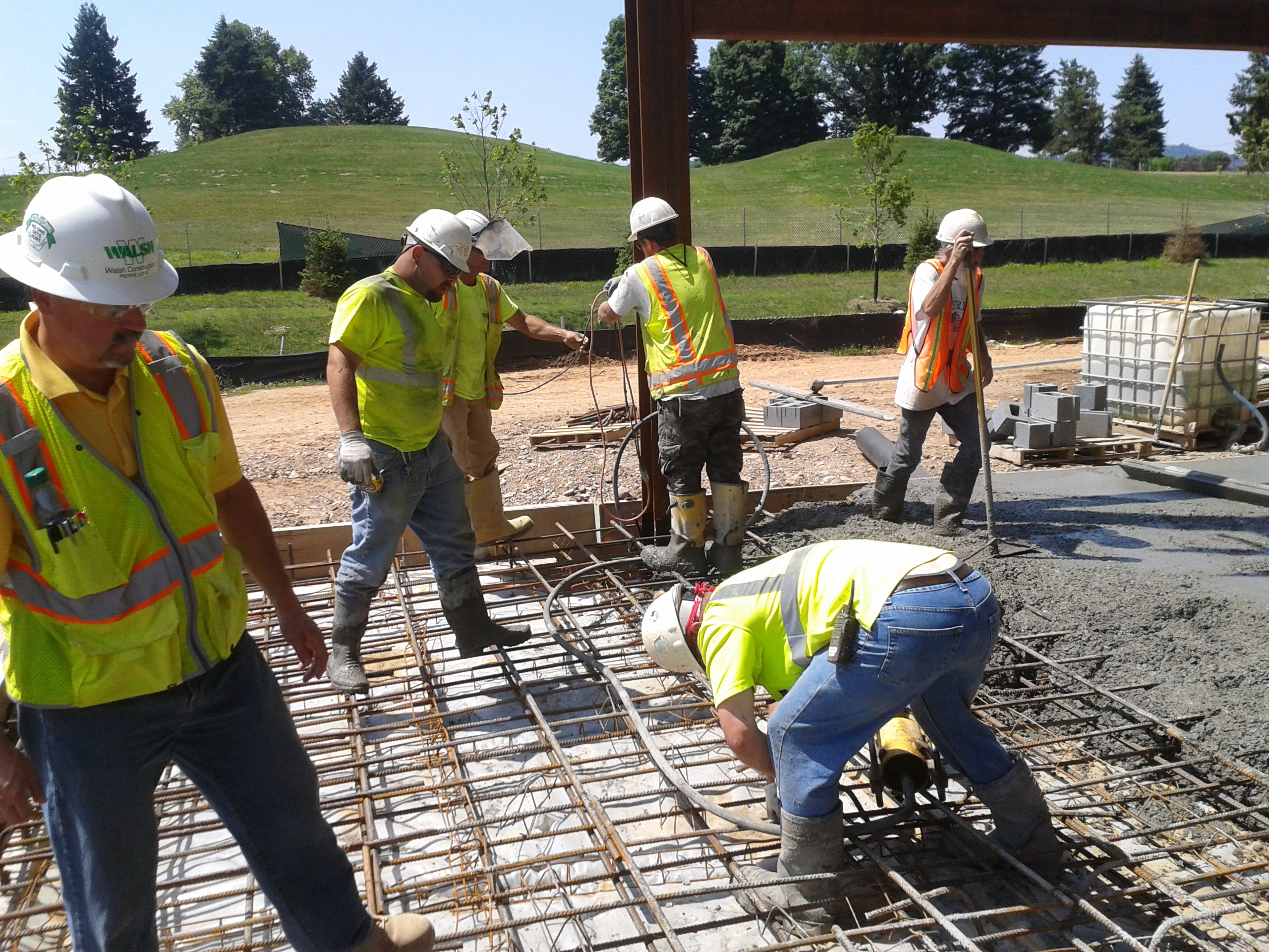
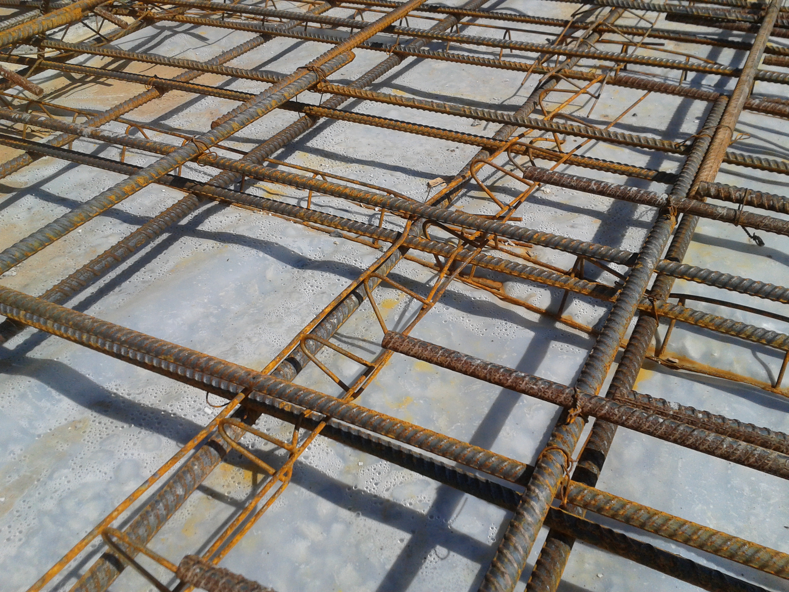
The final pour of the HQ’s Area F for slab on grade happened today…actually it was supposed to be tomorrow! The concrete subcontractors took it upon themselves to pour the slab – in my view so that they could rush off site finally and start another project down south. I’m yet to get to the bottom of what exactly happened, but as I was about to start to look over the rebar I found the concrete pump vehicle parking up next to me and the concrete crew moving to my area from their last slab pour. Having not seen anyone, I presumed all must have been in place with regards to checks and that maybe I had just missed a beat. Nevertheless, I continued to check over the steel as the pour started and started to find problem after problem. What then ensued was one of those awkward situtions where the USACE QA guy with the funny accent had to step in and stop 10 grizzly concretors and cause a back up of several concrete trucks. Clearly the commotion and grumbling resulted in the QC manager and various Walsh engineers rushing out to see what was going on. It then turned into a mess of fresh concrete being dug out, formwork being replaced, and concretors swearing at each other trying to rectify errors I kept raising – Joe, I can sympathise! Problems, to name but a few, were as simple as:
1. Top rebar not being tied down.
2. Top and bottom rebar having clearance from formwork as little as 1cm (should be 2” = 5cm)
3. Laps not being tied together.
4. Rebar seats having been crushed causing a spacing of, at worse, 2cm between top and bottom rebar (slab thickness – 25cm)
Thoughts….
– Only one external QC guy is employed to QC all concrete, cementitious material and rebar across the whole site. He believed the pour was happening tomorrow and intended to check the rebar this morning with me; this meant that when the concrete trucks turned up, he couldn’t check over the steel and was pulled away to do slump checks on the incoming concrete. To add to his confusion he was trying to QC the grout being used for masonry. It is clear to see that QC is starting to slip off the agenda as contractors rush to make up time, and QC is not a deciding factor when scheduling works that overlap – IT SHOULD BE! QC employment and scheduling needs to be thought through cleverly – many a day he has nothing to do, and is there purely because contractually he has to be. This is crazy and I feel his presence is starting to become a box ticking exercise!
– I read an interesting article about ‘QC and continuous education: providing tools for contractors to make ethical decisions’ – BLUF how HR depts need to employ QC workers by personality type, by using tests such as Myers-Briggs in the interview phase, to ensure that QC workers are capable of making ethical decisions. Today was case in point – Walsh’s QC manager told me he had walked the rebar this morning (he was clearly aware that the pour was happening); that was before I then showed him the errors. Hoping he would then rectify the problemsand relieve me by directing the concrete sub-contrators, he limply tried to stop the concretors pouring concrete but then just shrugged his shoulders when they couldn’t hear him…I then had to wade in again. In addition, the external QC checker should have had the balls to raise the issue straight away to the QC manager; if I hadn’t have turned up, the pour would have just carried on!
Never a dull day…
More Electrical Issues
A combination of Imran leaving and some of the other SPAs being on holiday have contrived to make my life considerably busier, but in a good way. I have now taken over all of Imran’s tasks, the HP Cooler Replacement, the Minox Blower, Flowline Supports and the closeout of LP and MP Cooler Replacement from 2013. On top of this, I am still responsible for the Retrofit of Cabins and I’m intrinsically involved in the Lifeboat Modifications. I’m not going to touch on all of these areas, just the closest crocodile, which is a problem with a flushing skid for the lifeboats. I would appreciate any good ideas that may be out there.
The Detail
This job has not gone smoothly, it has had problem after problem and nearly all of them could have been avoided. The latest issue involves a flushing skid, which is a piece of equipment used on hydraulic equipment to clean the components and test the system. For the lifeboats job we are recertifying the davit A frame, which is used to recover the free fall lifeboat from the water if necessary but on Clair the davit and A frame have not been used in 9 years. Anyway, the flushing skid required has to meet certain criteria in order to adequately flush the system, in this case it needs to produce a Reynolds number in excess of 4000 and NAS of 6/7 but not to exceed 7. The job is due to start on 7 Jul, with the skid required in early Aug and a skid has been procured and been shipped offshore. The flushing skid that has been procured has a motor with the following ratings; 37kW/400V/50Hz and 43kW/460V/60Hz.
The platform conditions are 440V and 60Hz so a fair assumption is that the power output is closer to 43kW than 37kW. Depending on power factor and efficiency of the motor, it could draw up to 78A. I do not have a data sheet for the motor so I have assumed 0.85 for both. I have approached the manufacturer and vendor and requested the data sheet.
The flushing skid starts using star delta and as such it requires a 3 phase and neutral supply. The problem is that the platform only has a maximum of a 63A, 3 phase welding point from which to power the skid. Since it is the SPA in charge of this job in on holiday I have been left to try and resolve the issue and I am trying the following three options. If anyone has any better ideas then I’m all ears:
- Install a temporary JB and use a single cable from this to hook up the flushing skid once it is in place. Then, detach the cable, move the flushing skid to its second location and hook the downstream end of the cable back up to the flushing skid again. There is a switchboard that appears to have a spare cubicle, it looks like it has 3 phase and a neutral and is capable of taking 200A. However, there is conflicting information because the platform as built shows no neutral but the ABB as built shows a neutral. I have requested that the REP offshore checks what’s inside the switchboard and get accurate information. I sense this will take a lot of time and effort because it will require workpacks, isolations, method statements, a temporary electronic management of change, cable calculations and the procurement of materials.
- Get a new skid with a motor of a suitable rating to be able to be powered from the 63A welding socket and yet supply enough turbulence. This is my preferred option. It sounds the best on paper but I have no idea whether a suitable unit even exists.
- Source a suitable generator to power the flushing skid. It sounds a bit like overkill to get a generator for one flushing skid, and there may be problems with exhaust fumes and footprint depending on size of generator. That said, I know I’ve got a flushing skid that works already offshore so this is just the other half of the equation.
Since time is tight I have decided to pursue all options with equal measure and try and get a solution asap. I wanted to avoid holding out for option 2 and then find out it’s not viable in a week’s time.
What is frustrating is that this machine was released by OIS, an inspection vendor, as safe to use. This is the second time on this project that an electrical engineering problem has slipped through the net and caused problems further down the line.
In other news…
Brendan and I had to help out at Banchory Beavers Summer Camp. All I can say is that Brendan is bottom of my prospective babysitters list. He was beasting 6 year olds and at what point said “Listen in means you stop talking and listen to me or Nick. Oi chap, do you have a problem?”
Imran’s leaving do was a success. He got so drunk he lost his keys and slept outside.
Red card moments!!
One of the constituent parts of the plethora of concrete mixes used on the Crossrail project, is Pulverised Fuel Ash, or PFA. A waste product from coal fired power stations, the material is ground down to a fine powder, mixed with heated air and burned. This forms a proportion of the material (about 20%) into fine glass particles which are separated from the remaining material.
This material has a number of uses in the construction industry;predominantly as a construction fill; as a raw material in cement manufacture, and most pertinent to me as a partial replacement to cement in concrete. This has a number of benefits:
Economic -reduction in the overall quanitity of cement purchased, and consequently a reduction in cost by using a waste product (relatively very cheap to transport from the power stations)
Environmental – green credentials in recycling waste product without the need to dispose of the stuff.
Technical. A number of technical benefits occur from the use of PFA as a constituent of the concrete mix, including:
– improved long term strength performance
– improved durability through reduction in mixing water
- – improved cohesion and workability for a given water content
– improved surface finish
– improved resistance to sulphate attack(ground water levels are on the rise in London, and in my little corner of the Lambeth Beds, there is an increased risk of oxidised pyrite leading to corrosive acidic groundwater)
– reduced heat of hydration (important in our specification as the concrete musnt remain below 60degrees during curing…difficult in summer…our tunnel reached 42degrees yesterday!)
– reduced shrinkage and cracking (see above!)
– reduced bleeding
– resistance to alkali-silica reaction
All in all, its good stuff to have on board…
So why do I tell you this? Keen to hear from all you concreters out there about reduced stocks of PFA in the UK. Our supplier CEMEX has withdrawn all supplies without notice. Without all the facts, it seems that it is a direct result of many of the coal fired power stations switching to gas. Hansons, the concrete supplier, run out of PFA as at today, and having explored all other options with no joy, have advised that we revise our mix designs sharpish! This affects all their customers, not just Crossrail, and I would imagine other suppliers are feeling the pinch too. Anyone else had this buzz? (When I asked Steve whether he’d had the email about the PFA, he point blank refused to return to Chatham to run a mile and a half! Thats not what I mean….)
So what?
Hansons are contracted to supply us with concrete to specification. They ultimatley are not achieving that, so contractually it seems very simple. However, the pressure of the program mean that the blame game is slightly moot. This apportionment will no doubt will be thrashed out later, but right now it’s in our interests to review these mixes and return to production
In terms of where the blame does sit and who ultimately wil pay for this…does this count as a ‘force majeure’, being as it was, unforeseen?
