Archive
Drove my Chevy to the levee, but….
the levee was dry…well not yet actually, because we still haven’t approved the dewatering plan!!
The Danville flood wall remediation is now in full swing, and is taking up all my time (not helped by the 5hr return journey to site), so my attention has switched from the HQ DLA. To be honest, it’s no bad thing as struct/civ involvement is now minimal, and I’m not getting much more from it. Instead of being a small fish in a big pond, I now have the con which is really satisfying.
I have managed to get hold of some photos of the damage caused by the Hurricane in 2011 to the wall – the raise d’etre for my remediation project…
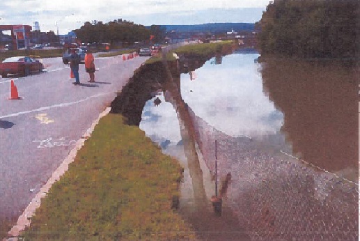
Looking south; the washed away wall sat 1m to the right of the fence

Looking North-East once river level lowered; the area to the left of the wall is what was washed-out (30m of wall).
The list of issues we’ve had is endless; the primary headlines are as follows:
– Unforeseen ground conditions. The biggest issue to date – who would have guessed??
- The temp shoring plan was designed by Larson’s group and hinged on tie-ing into an existing sheet pile on the north end and into the existing concrete wall on the south. Of course, as luck would have it, despite us supplying drawings that showed a sheet pile, there hasn’t been one found to date. As such, the excavation on the north end has had to cease at 5ft until a solution is devised – initial discussions with the designers suggest trying to minimise cost and time by using some of their H-piles they have in their yard and slotting in timber lagging between them. Of course there will be an REA submitted by the prime for lost hours and unforeseen ground conditions (USACE has to approve any new design iot prevent Heath Robinson work…and the approval is allowed to take 30 days!). This will be heated negotiation – from our standpoint, though the drawings were wrong, we did not dictate the shoring design of tieing into the sheet pile so the risk of it being there was borne by the designer. The other issue resulting from the lack of sheetpile is how the actual wall will now end, as we had designed it to tie into the sheet pile. After much debate, we agreed that if a sheet pile was there it wouldn’t do much anyway to cope with an extreme flood event as seen in 2011. In addition, we are fully conscious that this design is extreme overkill and forced onto us by the Dept of Transport – we would have been content to leave the remedial solution of rock armour fill and be done with it. Thus the wall will end abruptly but be surrounded by rock armour.
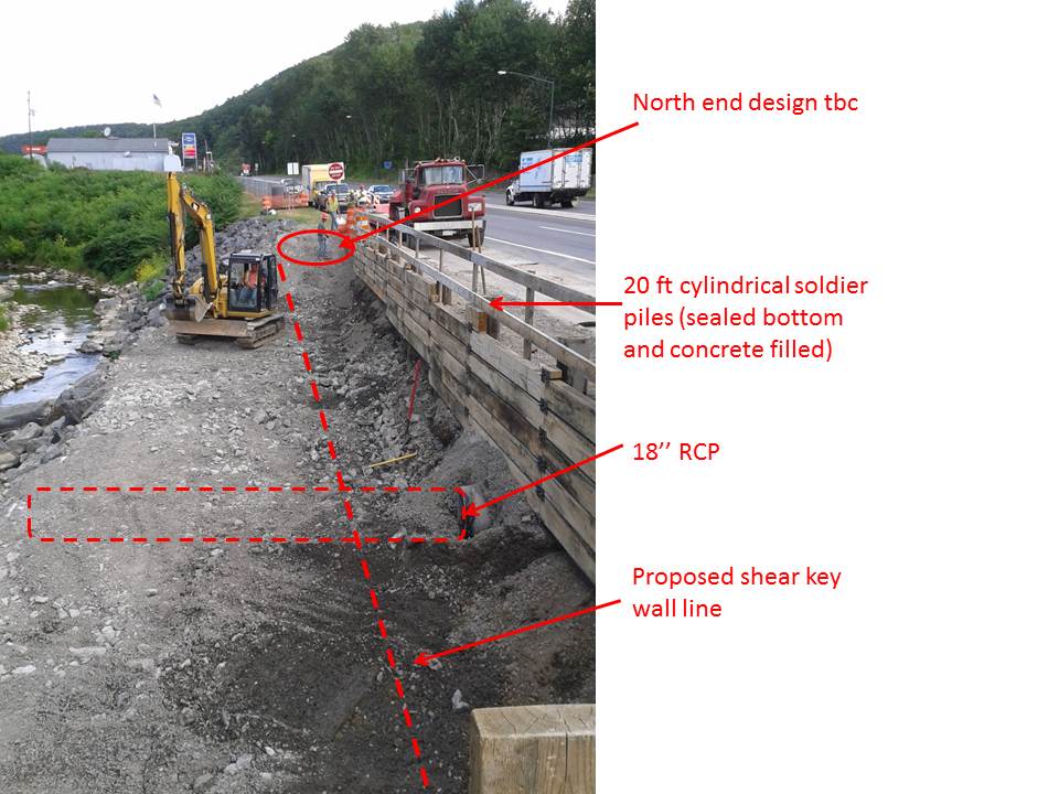
Looking North, standing on existing wall
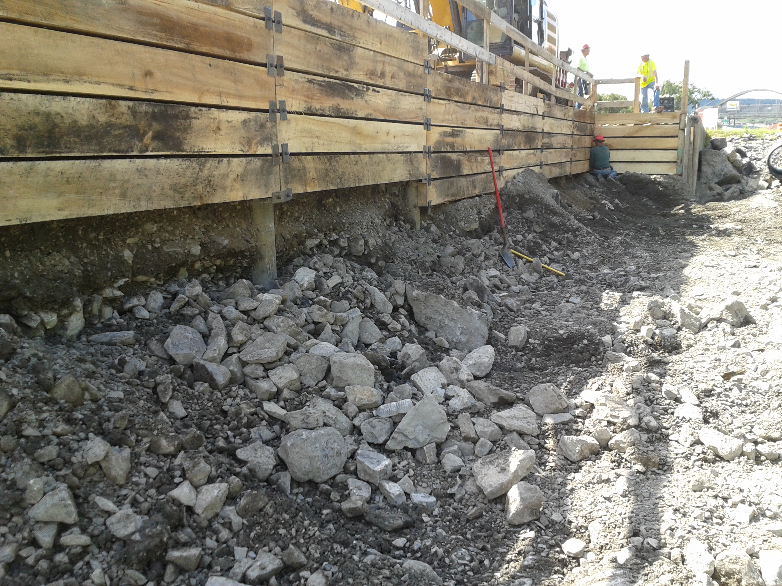
Looking south, excavation in 5ft lifts before lagging and welded attachments installed
- The geo-analysis and boreholes indicated the necessity for drilling through ‘rock’ (betw 8-10ft) in order to gain their sample to 22 ft. That therefore pushed the shoring design immediately away from sheet piles to the present circular tubes with welded bolts and plates and timber lagging. To date, I can count on one hand the amount of ‘rocks’ (>30cm) that have been excavated – normally parts of broken up concrete wall used as emergency fill; the remainder is 95% gravels – everyone is therefore asking the question as to what happened with the borehole samples (3 taken; 1 every 10m), especially as the shoring redesign was one fo teh main causes of several months of delay.
- The damaged concrete wall is now starting to be unearthed – we are unsure how much is there but I estimate at least an 18ft length (x 2ft width) at present. This will incur removal costs that have not been agreed upon as yet as it was guess work as to how much we would find…additional homework with answering RFPs.
- The 18inch reinf concrete pipe that runs perpendicular through the site taking runoff from the road to the river was initially decided to be dealt with by propping it up. Upon excavating down to it, it is actually damaged so has been removed and temporarily replaced with a plastic pipe. This has actually expedited site work, but we will have to pay for a new one.
– QC and safety ability of the prime. The prime has used their own guy as the QC rep and the safety offr. That is fine…if he was actually capable. Every time I have been on site there have been issues. To be fair at the moment there is not a great deal to check QC wise, so errors are pretty obvious. Annoying that I have to pick them up which results in disappointed Dad type chats…to a 50+ yr old! Somewhat aggravating as well that every question I ask, his comeback is: ”Let me ask the sub”! (the sub is essentially running the show!). Another classic was my question on D+2 – ‘where’s the E&S control’ (a pre-req for any constr); reply: ‘there isn’t any’! Needless to say that was the wrong answer; upon me going through E&S plan which he submitted to USACE I then asked where the Inlet protection was (i.e. filter bags attached to drain grillages) to which his response was: ‘What’s inlet protection?’…queue more disappointed Dad expressions, turn the page and show him the drawings!! As for safety, his inability and inaction has now become almost humorous – taking photos of welding (with welder and assistant not wearing eye pro!), workers not wearing high vis (in a heavily trafficked zone), standing right next to an area that has caved in behind the shoring and not thinking to do anything about it. Sadly, today I’ve been writing up an assasination on him upon request of the USACE area engineer who will use it as additional arsenal when chatting with the prime’s CEO and scoring their performance on the gov database. These nuggets are but just a few of his errors; he takes great photos though!
– Specs, drawings and standards…who wins? Well, of course standards do, then specs and drawings. The ‘as-built’ drawings (built in the ’70s) show joint spacings at 30ft intervals. As a result, the contractor has planned their formwork, rebar etc for such spacings under the pretense that the wall is to be built ‘as-built’ (total wall distance is 90ft). However, they have now seen that our specs say that joint spacings should be a maximum of 24ft, and the designers drawings show 20ft. Our answer to their obvious clarification RFI was that backed up by ACI and ASTM – a max of 24ft for a gravity walls. Queue – delays, rework, REAs, but again our standpoint is that construction must be done by specs unless superseded by standards – both of which coincide; we cannot be blamed or pay-out for errors resulting from using as-built drawings that were not built to today’s specs.
– Means and methods. As the government’s (client’s) representative we cannot dictate means and methods; this is quite useful at times for keeping one’s hands clean of risk, however I find it exceptionally frustrating when seeing things on site that can be expedited with a bit more planning and forethought, enabling concurrency of work. The QC manager however, though not particularly capable, is quite receptive to my ‘suggestions’ or ‘if I was to do it, then …’. A potentially major problem has however cropped up as a result of not knowing the means and methods when approving plans in piece meal. I have grave concerns that there is no sediment control on the most obvious largest issue – the excavation; thankfully the plant op is pretty handy so debris has been minimal if not nil, but all it will take is one storm and tornado and the pristine protected trout stream will become but a cloud..and the Dept of Environment will be throwing down a rather hefty fine…on the contractor mind, not us. Just because we approved the drawings does not absolve the contractor of responsibility or risk; our rational for approval was that the dewatering diversion dyke would also act as a sedimentation barrier hence we approved it…the diversion dyke is part of the dewatering plan which still hasn’t been approved yet for a variety of fairly minor issues, and has been held up by the QC manager for a week having mislaid its location in the approval chain on the bespoke USACE IT system that we use for communicating drawings, specs, RFI, REAs, submittals, payments etc.
In other news, the family headed out on a long weekend roadtrip through Pennsylvania into New York state, stopping off for one night at Finger Lakes renown for its countless wineries, then up to Niagara Falls – amazing experience, and well worth the miles! 

