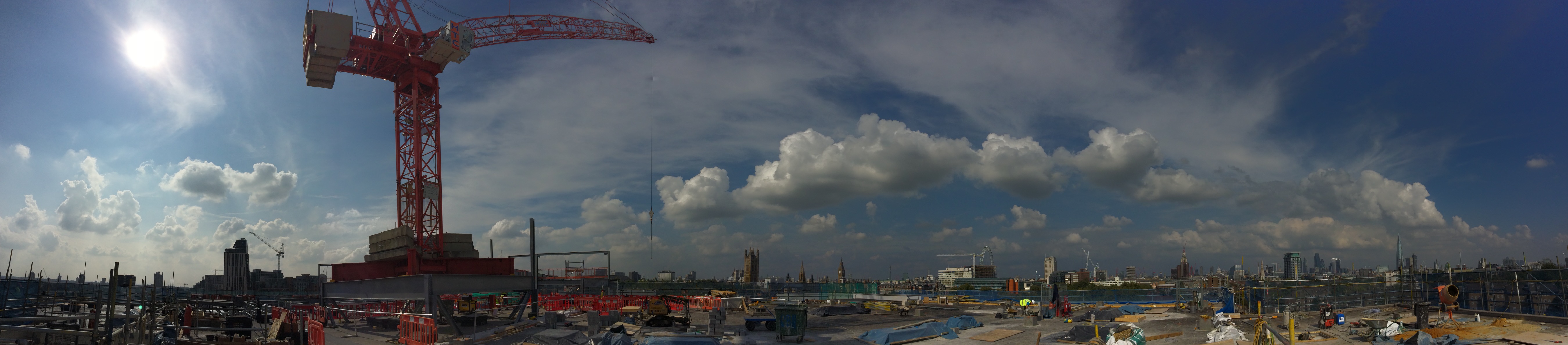
Cranes alongside railways
As well as my work on the South Bank Tower I am also the Construction Engineer for Mace at a small site in Lambeth, at a Metropolitan Police Station. This police station is a forensics lab, headquarters for a firearms unit and also a communications HQ for police and fire calls.
Maces scope of works is predominantly M&E. We are relocating the existing plant onto the roof of the existing five storey structure. Originally built in the early 1970s it was first used by the Royal Mail as a sorting office and as such is a very robust structure with 14 and 18inch thick floor slabs, with RC columns in approx. a 10m grid.
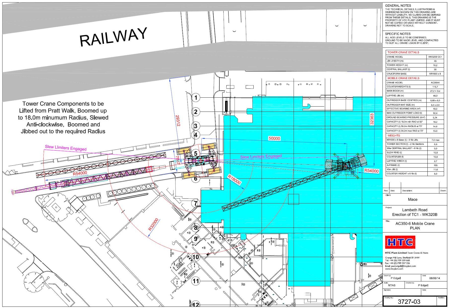
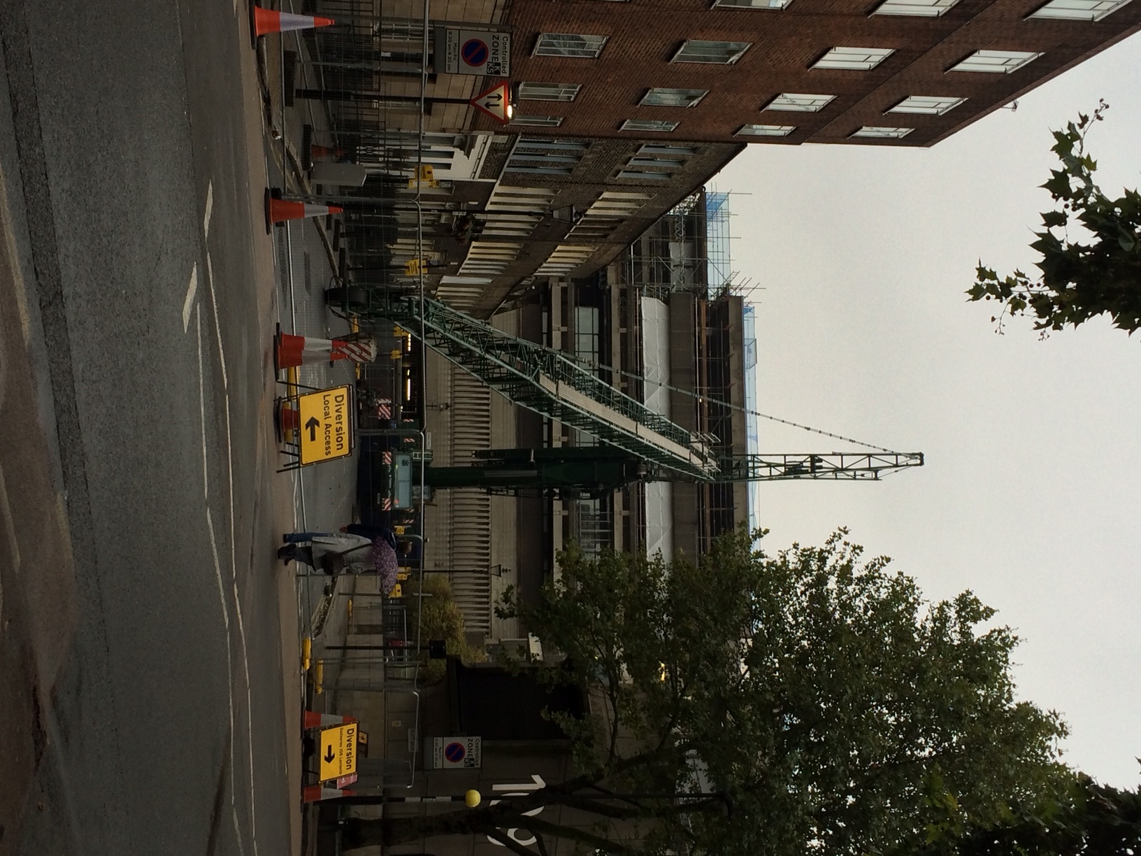
In order to relocate the plant onto the roof, a steelwork grillage is to be built in order to allow the high permanent dead loads to be bear directly on top of the existing RC columns, instead of the roof which obviously is not strong enough. Being London the site is particularly constricted. To the east is the rail mainline into Waterloo (the Reading line), to the south a narrow road, to the west there is no access since there is a hotel and to the north there is a small residential street used by the police for access.
The key challenge for me has been to plan how to erect a tower crane on the roof of the existing building, which will lift all the plant into its position. This needed to be achieved with limited access and immediately beside a live railway. Network Rail require anyone working beside the railway to have an agreement in place and any works which could impact the railway to be signed off by their Railway Asset Protection Team. As part of the approval process the principal contractor has to nominate a Designated Project Engineer (my role) and a Contractor Responsible Engineer (min Chartered Engineer).
Network Rail operates in a risk focused manner. They trust nobody and everything that could potentially impact the railway is scrutinised to ensure the risk has been appropriately managed. Obviously using a mobile crane to erect a tower crane on the roof of an existing building and then operating a tower crane to lift pieces of plant, up to 10 tonnes in weight, is relatively risky.
Managing the risk effectively, thereby reducing the level to an acceptable level for Network Rail, required prolonged engagement and forward planning. We had to demonstrate we had explored all alternative options and the chosen option then had to be designed and category III checked. This task was doubled with having to design and check both the mobile crane, and the tower crane.
Tower Crane Grillage
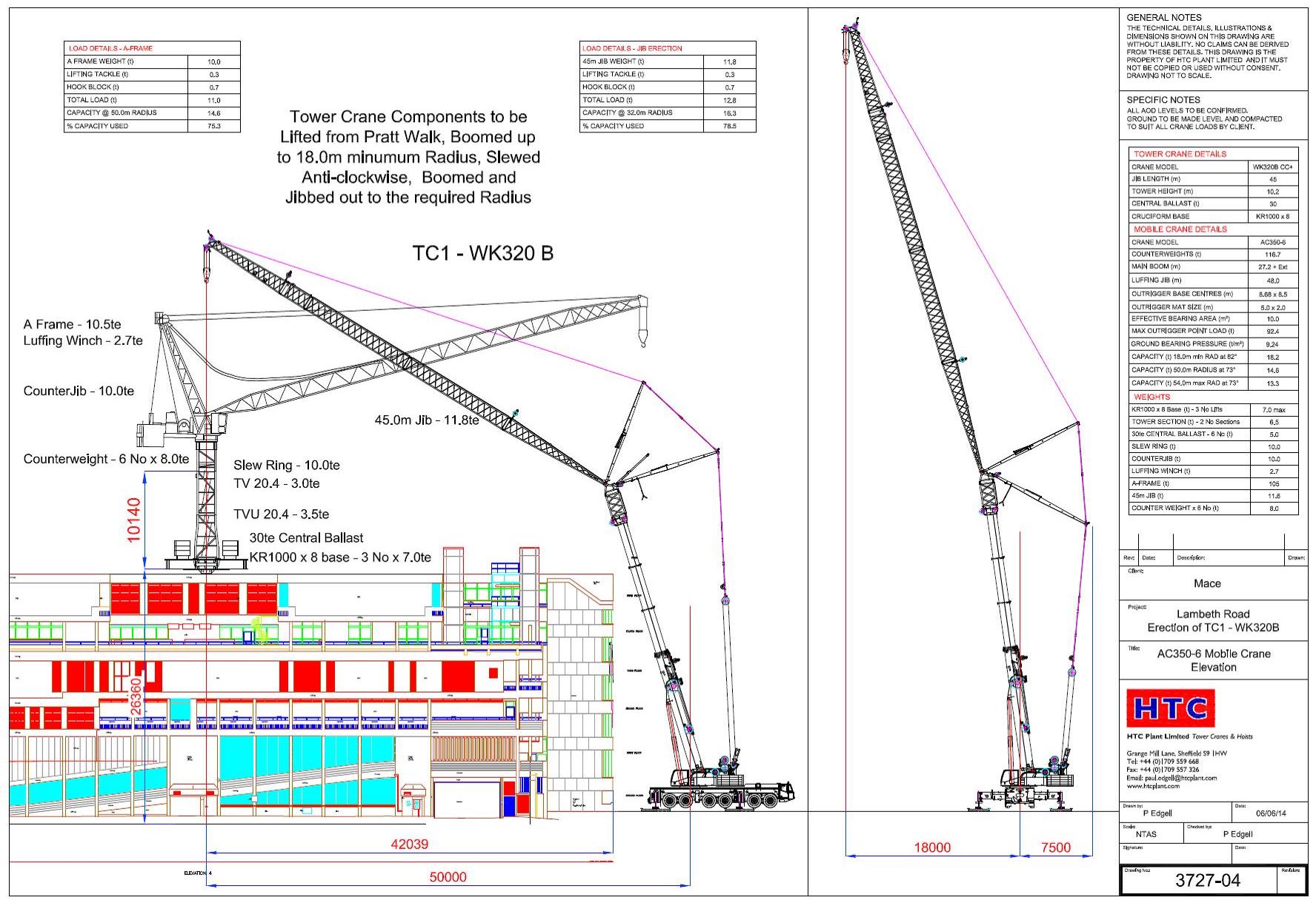
For the tower crane, in order to progress the early design of the tower crane I undertook initial design feasibility to determine the scheme was viable and also give the steel fabricator indicative sizes of beam for pricing. I then gave the detailed design and analysis of the crane grillage (utilising the permanent works steelwork) to a temporary works designer to complete. In order to verify the existing structure was adequate to support the tower crane loads, combined with plant loads, I then undertook a detailed analysis of the building.
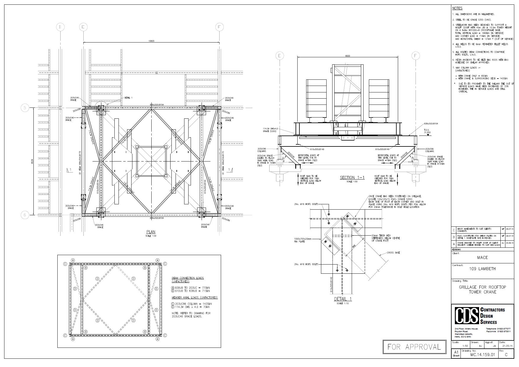
The steelwork grillage design and building verification was then category III checked by an independent engineer.
Mobile Crane
I undertook the design of the mobile crane foundations. The only workable position was for the 320 tonne mobile (a Terex AC350-6) was to situate it in Pratt Walk, an urban road between the police station and a row of occupied residential house (separating the crane and railway).
Two of the four mobile crane outriggers I chose to position over basement walls of the existing building. This gave a direct load path of the load into the raft foundation of the building.
The remaining outriggers I had little choice but to position in the road. We conducted a sub-surface survey in order to identify any services near the surface. I verified the pressures from the crane in the same way as designing a foundation using C Nc, Gamma N Gamma …. The cat III checker did similar.
The Issue
Everything was signed off by Network Rail, after much stress and a presentation of our plan the previous week. The mobile crane arrived on the morning of Tuesday 26 Aug 14 and a 60T mobile erected the jib of the AC320-6.
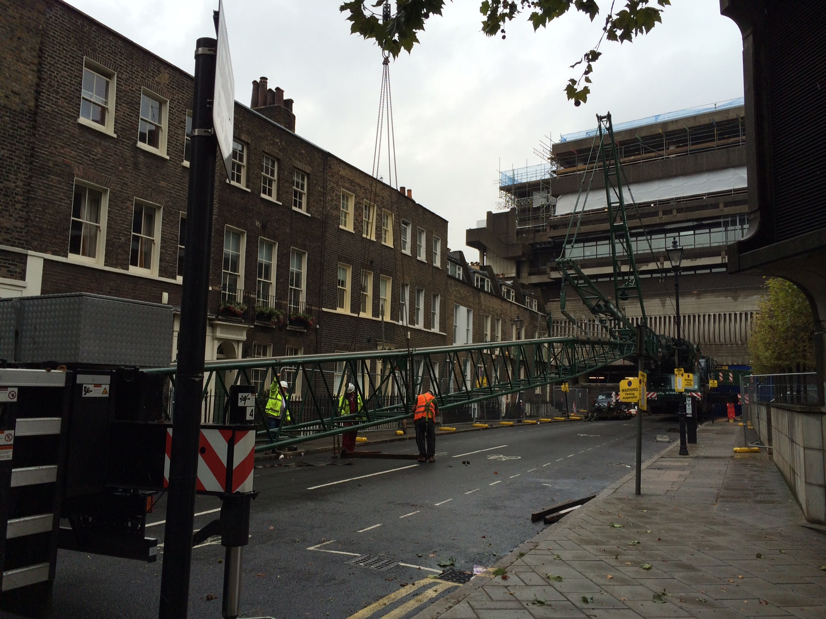
On Wednesday morning we raised the jib of the mobile and the steel wagon arrived.
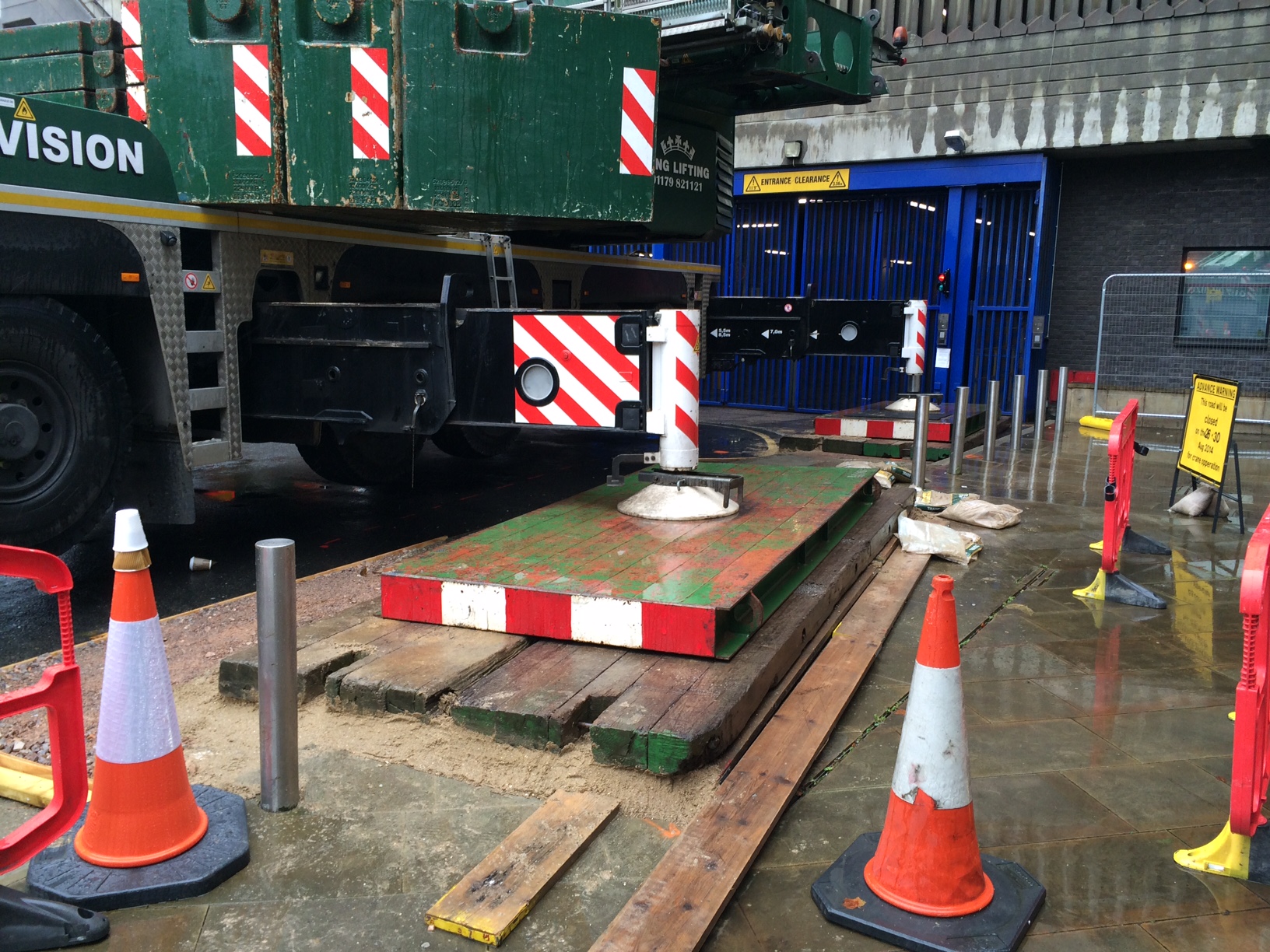
Having realised all 120 tonnes of additional counterweight on the AC-320 the crane, water started to appear from beside one of the four foundations (nearest the railway). I was on site, having earlier signed off the foundations, and lifting operations were stopped immediately. The crane was slewed such that the jib could then be lowered safely back down to the ground. During this time the leak got worse and we discovered that most of the water from the broken water main was making its way from under the road directly into the police station basement, next to the LV switchroom!
We now had a bit of an emergency and potential PR meltdown for Mace! Eventually we managed to isolate the water main and stop the leak. We narrowly avoid shutting down the LV switchroom room and the crane did not de-stabilise in any way.
Immediate Action
Following the event our immediate focus was the safety of the crane in order to ensure it did not collapse and was then the fabric of the building against water. Following this we then had to get Thames Water to site to access the leak and fix it. The Mace project director chose to keep the mobile crane on site (with incurred standing time). We had a backup road closure for the following week so chose to keep the crane on site. Without the backup road closure we would have had a 14 week delay in order to secure another road closure.
Summary
I had identified a water main 1m below one mobile crane outrigger at design stage. I had sought advice from my Mace engineering supervisor who advised that since the average ground pressures were around 100kN per meter square (10tonnes/sq m) this was acceptable and the risk was acceptable.
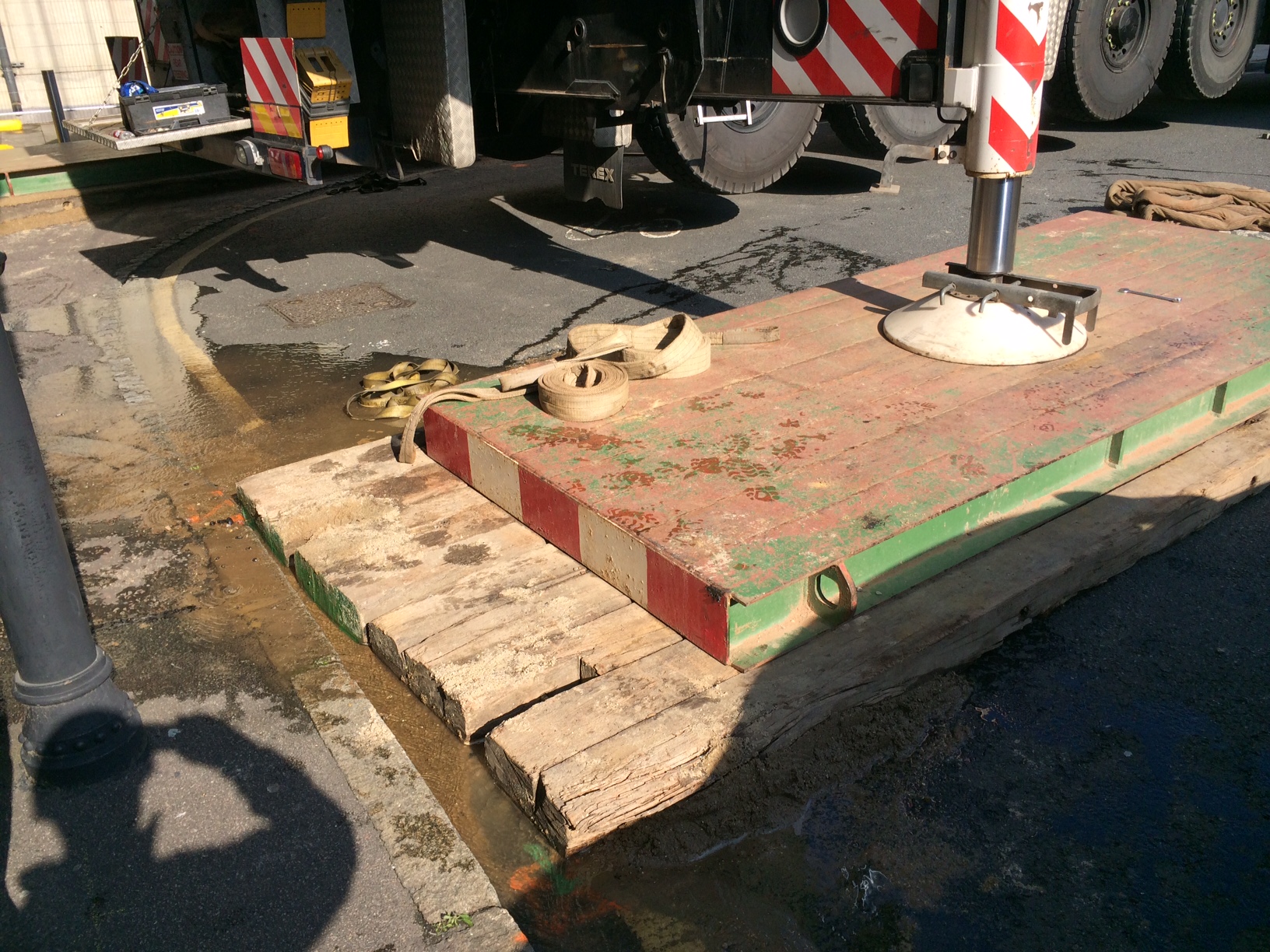
20140827-Mace-109Lambeth-Mobile Crane Outrigger New Matt Configuration
What I didn’t do was communicate this risk adequately. It was not on the mobile crane contractors risk assessment. The police were not aware of the risk. Thames Water were not aware of our plan to position a mobile crane on top of one of their mains.
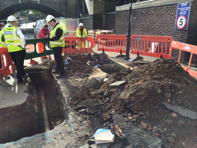
The leak was caused by a ring fracture. Although Thames Water would not say it the pipe was old but this was no excuse. I re-designed the outrigger foundation with a larger matt and used a deeper layer of sand beneath the matt to ensure pressures were evened out as far as possible. Thames Water replaced the cast iron pipe with a section of HDPE pipe. Network Rail signed off the foundation (again) and the mobile crane was erected successfully. The tower crane grillage was then lifted onto the roof. Erected and then the tower crane was erected and tested. Thankfully all this went seamlessly.
Some significant lessons learnt for me. All part of the experience! Risk registers are key and must be communicated. Get all the stakeholders involved early. If you can reduce risk in any way then do it (ie increase the size of the crane mat).

Good blog Rich. Who was it that decided on the crane to be used and design the lift of the components? Did you get any say in the process? I’m guessing it was this person that gave you the loading for designing the grillage under the outriggers? I also know that the new liebherr cranes have an active monitoring system that tells them the load going into each of the outriggers, it might have helped identify any problems in this case?
Thanks Pete. AECOM designed the permanent works. There was actually little thought by them or Michael Lonsdale (our M&E sub-contractors) as to the weights of the pieces of kit going on the roof. We are having to retrospectively break the chillers down and lift them without any coolant in, in order to reduce their weight. This is another risk reduction activity ensure the crane works at under 80% of its rated capacity.
The Terex AC350-6 did have the active monitoring. The outrigger leg load was around 80 tonnes at the time of failure. Using pressure bulbs with a 2m wide mat the pressure at the pipe (1m below the surface) was around 75kN/m2. Should this load have fractured a 4inch cast iron pipe???
Rich, Lessons learnt for all, im am surprised at the size of the crane mats you initally used. We have had similar sized cranes on site and loading from the road adjacent to the site. The crane mats we used were at least twcie the size of the one on you site and requireed a smaller crane to lift into position. What information concerneing the raod and the subsurface utilities were givento the temporary works designer, was this just bad luck or could this have been avoided with better information?
Steve,
Information wasn’t the problem. I had the sub-surface information, as did the checker. We also conducted a plate bearing test. This did’t tell us much since the diameter of the plate wasn’t large enough to influence the pipe.
Advice I was given was that so long as the ground pressures are down to 100kN/m2 then it is safe to load. Should I have question this advice further? Maybe yes.
Was this bad luck? Maybe a little, but as I said we didn’t do everything we could have to limit the ground pressures to begin with.
As you remember a shear failure of ground beneath a foundation will occur in depth B where B is the width of the foundation. This implies that the shear stresses here are significant. When you look at most piling matresses they’ll import about 600 to 1000mm of fill and place their outriggers on that – for good reason…they are controlling the material in which the shear stresses are to be high….so, without being smart after the event…….the rest reamins unspoken
Those were my thoughts too. I had considered the boundaries to my problem. When given advice that the pressures we had were acceptable then I preceded.
Is there a maximum safe pressure that can be exerted on buried services?
Rich
An excellent blog well done. Good CPR stuff and lessons learnt all round.
Kind Regards
Rich,
Unfortunately there is no such thing as a safe bearing pressure that you can apply to a pipe because there are too many variables – bedding material, ground water, pipe material and geometry (wall tickness & diameter) to name but a few. Clearly if pressure is applied evenly all around the pipe (High w/t and porosity?) it will survive a greater loading than crushing loads with out any confining presure… The other way to view it is that the ground will arch over at about 2D above the pipe (very crude value, D is pipe diameter, no supporting calcs offerred but see St. Venenant!); the pipe will then move with the ground so if the ground doesn’t shear the the pipe will be OK and I refer you to Mr Moran’s comments above…
All of this says yes there is amximum safe pressure and it is site specific every time – actions, geometry, materials.
Nice piece of work this. Don’t beat yourself up about the issue because there are others who should have saved you from it and it would seem that the handling of it was a significant success. No panic, neatly contained, controlled and mitigated.
If it was Carillion they would have filled the road with a 450mm (min) 6F2 pile mat and concreted any void that may collapse! Almost everything we do on the western side of the site goes through the NR submission process-was it Tom Smith you dealt with?
I have just been checking the RAMS for our caisson that we are sinking for the microboring (was pipe-jacking). It is right next to our HV cables and on the boundary line of the NR fence!
All our temp works designs come from the sub-contractors and get checked by the Carillion TW Checker who works at their main office-it is a shame we don’t have someone on site doing it-I think there is only 1 chartered civil engineer in the whole office!