Lunatic Asylum
On my second day in the Jacobs design office, a call came in from a Brisbane mental asylum for help with an existing air conditioning system. The system was installed as part of a refurbishment of a single story heritage building within the asylum grounds in 2008, and has not worked properly since. The installer has made several return visits to ‘fix’ the system but has failed to do so. As the warranty has now expired, the maintenance team decided to employ a consultant to fix the problem once and for all. I put my hand up to run with the task.
The Task
Design an air conditioning system for the building which uses the existing split units to best effect. The solution must also be feasible to install whilst complying with the restrictions placed on heritage buildings.
Background
The buildings principal use is for offices, and the nature of staff complaints suggest issues with the capacity of the system and with air distribution. Someone, somewhere is either too hot or too cold, and any attempts to fix the problem have just shifted it to another room. I went to recce the job and found that they currently have 3 outdoor condensing units, each with a cooling capacity of 15.2 Kw, on 3 refrigerant ring-mains, feeding a series of indoor head units of varying capacity. It was immediately obvious that the indoor head units were poorly distributed among the rooms, and that there was no outdoor air supply other than natural infiltration. I collected details of the outdoor and indoor units, the room occupancy, noted the electrical equipment in each room and got a feel for the composition of the roof and walls. The site manager provided me with drawings of the building which had room sizes etc.
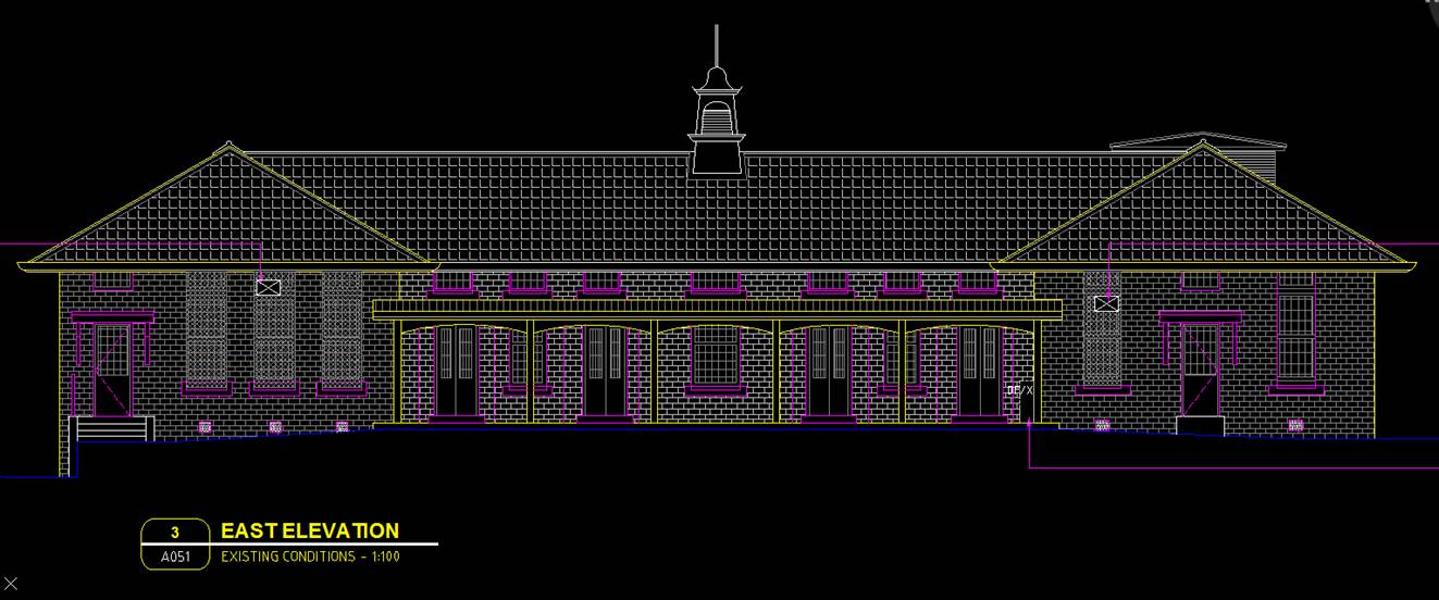
Figure 1 – East Elevation
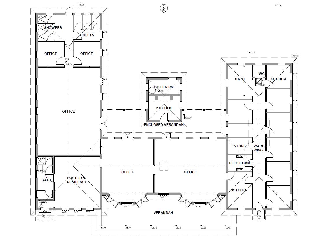
Figure 2 – Floor Plan
Due to the building being heritage listed, the site manager advised that the re-design should to use existing penetrations through the ceiling and walls. This will mean that refrigerant pipes will be visible on the inside of the rooms, and any ventilation will need to use either existing ceiling access panels (of which there are very few) or windows.
Heat Load Calculations
The heat load software used by Jacobs Australian offices is Camel, and is significantly less capable than Hevacomp as it only calculates heat loads. It took me the best part of a day to input the building data using the Camel manual as a guide. The project was an ideal size to learn the software and to figure out the little tricks that help speed up the data entry.
The key outputs from Camel were as follows:
- Individual room heat loads..
- Condenser cooling capacity required per zone.
- The W/m2 per zone, which gives an indication as to the accuracy of the output data – usually in the region of 200W/m2 for an office.
- Coil dew point
- Sensible heat factor.
The rooms are currently grouped into 3 zones, each serviced by a single 15.2Kw outdoor condensing unit as shown in Figure 3 below.

Figure 3 – AC zones and existing Fujitsu head unit layout.
The Camel heat load results clearly showed there was a problem with capacity in Zones 2 & 3, which tied in nicely with the information from the user.
- Zone 1 required a cooling capacity of 17Kw at its peak load.
- Zone 2 required a cooling capacity of 26Kw at its peak load.
- Zone 3 required a cooling capacity of 38.6Kw at its peak load.
So, the problem was three fold; insufficient cooling capacity for Zones 2 & 3, poor distribution of head units within the rooms and no outside air ventilation.
The Solution
Insufficient cooling capacity – Further divide the rooms into additional zones so additional condensers can be added to provide the required cooling capacity. Condensers to be selected form Fujitsu range based upon size requirements.
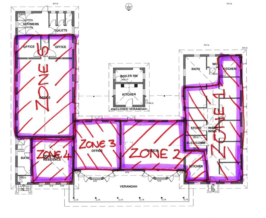
Figure 4 – Revised AC zones.
The revised zones require the following cooling capacity at their peak:
- Zone 1 – 17.0Kw – can utilize existing condenser unit.
- Zone 2 – 13.3Kw – can utilize existing condenser unit.
- Zone 3 – 4.48Kw – requires additional condenser unit.
- Zone 4 – 17.4Kw – can utilize existing condenser unit.
- Zone 5 – 20.3Kw – requires additional condenser unit.
Poor distribution of head units – Re-distribute head units and add units to rooms where current capacity is insufficient. The solution below utilities all but one of the existing head units but has an additional seven units of two different sizes. Figure 4 below shows the re-distributed head units. The purple represents a head unit and the number correlates to a particular unit capacity.
- 7 – 2.15Kw
- 9 – 2.8Kw
- 14 – 3.8Kw
- 18 – 5.4Kw
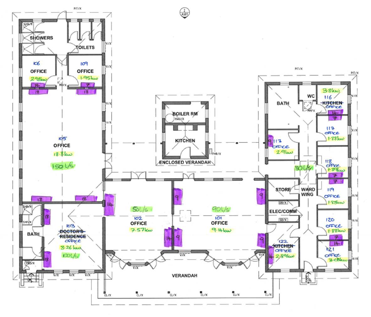
Figure 5 – re-distributed head unit layout.
Ventilation – Provide pre-conditioned air to each of the spaces so as to improve the efficiency of the system and reduce the load on the indoor head units. This is proving to be the most complicated part of the problem in terms of how to provide conditioned ventilation to each space, without any works that could cause problems with the buildings heritage status. The options being considered at this stage are; providing heat recovery ventilators to each room through windows, installing a centralised pre-conditioner in the roof space below the clock tower and ducting to the 5 key spaces (for zone 1 I am thinking to put air into the corridor rather than individual rooms), or a chiller unit with a chilled water loop.
At this stage, my thoughts are as follows; the heat recovery ventilation to each room would be the easiest option but the units are 1m x 1m x 2m and weigh 76kg so mounting them in a window (I cannot put any new holes in the walls due to heritage restrictions) would be difficult; the centralised pre-conditioner would potentially provide the best efficiency but it will depend upon the ceiling space available and flow/return air possibilities through the clock tower; the chiller unit seems overkill for such a small building and would require chilled water to be piped around the building.
I have spoken to a supplier to get and understanding of the options, and have another recce planned for tomorrow to see which options are physically possible….

Ben,
Have fun with installing anything large in the roof of a heritage building without causeing servicablility load issues on finishes!
I like the way you can lose over 9kw of cooling laod just by re-zoning – if you divdied it all up even smaller woulf it reduce again?
Richard
Well spotted! I should have pointed out that the revised zone loading also includes pre-conditioned air.
Thanks Ben, looks like a good project. A couple of thoughts:
1. Good to correlate the Camel outputs with user feedback; did you do any rough calcs first to ensure the answer you obtained from unfamiliar software was in the right ball-park?
2. What alternatives have you considered to provide a better solution outside the constraint of the site manager’s advice? As a PQE you are the infra specialist there to add value, not just to do what you are told. Whilst major refurb work and gaining heritage building consent may appear outside the scope of the fee bid, considering options at this concept stage is relatively cheap and is vital if you are to provide the client the best solution. The client may consider an alternative option worth the pain of building consent if it provides a more comfortable environment at reduced whole life cost.
David
1. I generated the results first and then discussed them in detail with the mechanical technical lead. There is a good deal of engineering judgement in the calculations but we went through the key outputs I listed in the blog as a check of the results. The relatively high W/m^2 raised some concern, as Mark points out below, but he was reassured when I talked him through the detailed parameters. I got a second opinion from a guy who has dealt with these types of buildings recently and he agreed that the results were reasonable.
2. The brief we received from the site manager was pretty broad “advice required on appropriate aircon”. The route we are heading down is as a result of discussions within the Jacobs team.
Ben
200W/m^2 – quite high but presumably for the climate and given you quote peak loads not unexpected?
Presumably the condenser ratings allow for increased cooling loads (ie 45.6kW of rated capacity will give you 81.6kW total cooling capacity)
David’s point 2 is worth considering and your options look like they are building up nicely but do consider more major changes, is there scope for a VRF system in place of the wall units for instance? Whole life costs down, more flexible, generally more comfortable etc……
What are the the constraints? Heritage building aside the function of the building is medical, do you have Aussie equivalents to Health Technical Memoranda to comply with? I’m thinking anti-ligature fittings and central control for instance.
For the Civils – 45.6kW may equal 81.6 kW once you’ve done the maths, don’t worry I haven’t gone mad.