Phase 2? Done. Hello phase 3.
Well I thought I’d kick off the New Year with a blog and step off with the right intentions.
I’ve been in the design office a couple of weeks now and it’s been fairly gruelling to say the least. Reading back through some of the blogs from this time last year it appears that the majority of the PET(C) 60 course experienced the same mixed feelings at the start of phase 3, with some hilarious inputs from Rich Phillips.
So I have started work with a small consultancy located in Scunthope, NE Lincolnshire and have quickly established that I am not cut out for the daily commuter grind and office environment.
The consultancy, CR Parrott Consultants Ltd was set up in 1994 by Chris Parrott (MD) as a structural engineering consultancy as he is a chartered structural engineer. Over the course of the last few years the company has steadily expanded and now employs approximately 30 staff across 2 offices. The company now offers a professional engineering consultancy, project management, technical support, architectural and 3D visualisation services. This is quite a broad spectrum of activities for a small workforce but reflects the nature of the work in the area as Lincolnshire is not renowned for its cutting edge civil engineering.
I have been placed in the structural engineering design team, headed up by the senior chartered (IStrucE) structural engineer with 3 further assistant structural engineers from various backgrounds. The size and nature of the company means that I am likely to get a good spectrum of exposure to the different consultancy disciplines with a real chance of being able to construct something I have designed during the 7 month period.
I spent much of my early time in a similar vein to the early days of phase 2, looking through job files and drawings, attending a number of briefs and re-sharpening my academic pencil. The Senior Structural Engineer set me a number of revision topics and seminars to work through for my first few days and over Christmas leave (!) predominately focussing on frame analysis and steel and timber design. All good stuff for the CPD log.
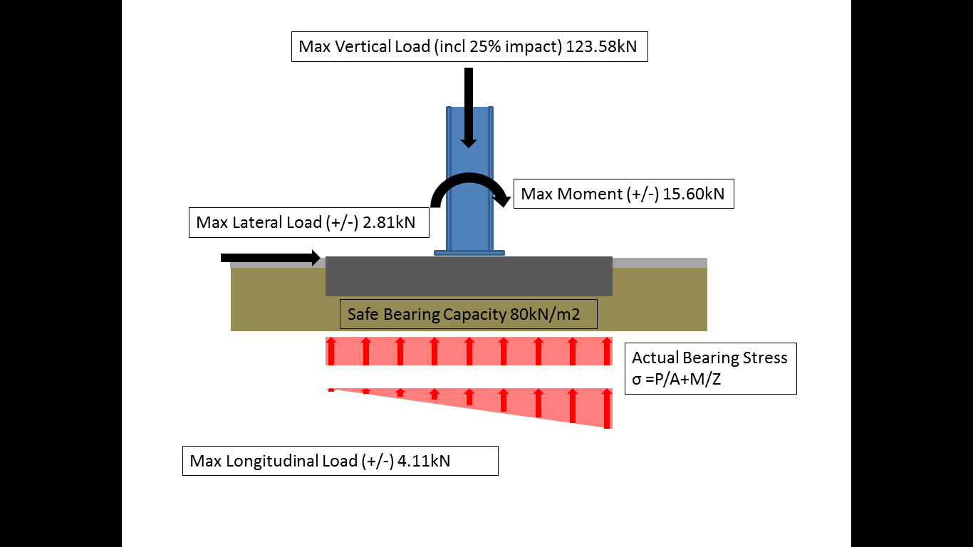
Last week I was given my first real design responsibility and it came in the form of a foundation design for an overhead span crane to be constructed inside a steel portal frame hangar. The initial job entailed a detailed survey and structural report on the existing crane runway beam positioned inside the building to ascertain whether it had sufficient strength to accommodate a larger crane (from 2.5T to 10T). It did not. This work was completed by the Senior Structural Engineer and the analysis revealed that the existing foundations and crane runway beams would be overstressed and incapable of taking the additional loads. A number of recommendations were made including a C-Section steel top hat surge girder on top of the existing beam (to improve the stiffness in the yy axis) or the use of RSA or CHS between the portal columns to reduce the effective buckling length of the beams. Both of these options were discounted due to the amount of additional work required to facilitate the construction due to the access limitations. This was sent to the client who subsequently came back to request a bespoke crane that will sit inside the building footprint. Whilst the consultancy would normally design the steel frame for the crane, this has been subcontracted out to the crane company who have an ‘off the shelf’ solution. This makes our life easier as we get the frame dimensions with the static and dynamic loads clearly set out, reducing our analysis time.

Existing crane runway beam.
Foundation Model.
So the first job was to assess the buildings footprint and establish where the crane would fit in the area specified by the client. This raised a number of issues including the clearance of the new crane under the existing and the proximity to the ground beams running underneath the portal frame columns. The building plans were located and the existing slab (180mm) was analysed and it was established that drilled and grouted bolts in this slab would not be sufficiently strong to accommodate the frame. So the plan is to locate an area where the frame will fit (in-between a number of drainage channels, not inside the ground beam footprint), break out the existing floor slab and construct some bespoke foundation pads for the frame columns, tied into the existing ground slab. Simple enough and a perfect warmer for yours truly. I have now completed the preliminary calculations for a RC foundation and await the familiar red pen of the Senior Structural Engineer prior to inputting the data into Masterseries for final analysis. I have also started the AutoCAD drawings that will form part of the portfolio of work that the client will receive. The following are a couple of reflections on my time and work to date that also form part of AER 4.
Reflections:
Design. It has become quickly apparent that it is much tougher to design structural elements within existing infrastructure than on a clear site or on in an academic environment. Whilst an obvious statement the challenge lies in understanding the design fundamentals enough to manipulate them as necessary to accommodate a functional yet cost effective and economic design. This is something I feel I am already learning and will come with practice and experience.
Seminars. During the first weeks of phase 3 I was given a number of design tutorials to work through, predominately in timber and steel design, to catch up with the other Assistant Engineers who had already taken the sessions. The seminars are led by the Senior Structural Engineer and occur on a weekly basis for a couple of hours in addition to a number of Masterseries training sessions that occur less frequently. These sessions have proved invaluable, not only as a good revision period but as useful hours towards my Continual Professional Development (CPD) Record. It is also a worthwhile personal lesson to see even relatively seasoned design engineers refreshing the fundamentals of design and highlights the importance of combating skill fade. This will inevitably be all the more important as a Professional Military Engineer and highlights the importance of maintaining a thorough CPD.
Software. The structural software utilised by CRP is the Masterseries design suite and whilst more complex than StaadPro, with a greater level of modelling detail that can be incorporated, the fundamentals are similar. The availability of the software across the team is limited and whilst the software is loaded onto each computer in the office a pen drive ‘key’ is required to open the software. This is controlled by the Senior Structural Engineer and seems to limit the amount of work the Assistant Engineers can do. I am yet to ascertain whether this is a product of licensing cost or a form of quality control across the team. The software has more applications that STAADPro and would be worth considering if the PEW system was ever upgraded.
British Standards v Eurocodes. The structural team work to the codes laid out in the British Standards not the Eurocodes. Whilst this is still a legally accepted practice it is frustrating to have to relearn the BS methodology after an MSc focused on the Eurocodes. This was the same as the design calculations produced by the design consultancy during my phase 2 attachment with Graham Construction. The only conclusion I can draw from the lack of adherence to the Eurocodes is the generation of Engineers conducting the designs and their reluctance to accept the change and embrace the new codes. I suspect it is also a product of the small nature of CRP as many larger international consultancies will undoubtable have made the switch to cater for their wider clients. The seminars have assisted in adjusting my mindset back to the BS.
Judgement. It has become apparent that there is a certain amount of license to make an ‘engineering judgement’ when it comes to structural design. Whilst it appears that the process is strictly governed by the handrail provided by the British Standards and Eurocodes there are times when engineering judgement is used to make a decision particularly in geotechnical engineering. This is something that partly comes with experience for which there is no substitute.
Experience. Whilst design Engineers may have an ability to make a design judgment, it has quickly become apparent that they can be quite focused on their particular part of the project and do not necessarily understand the larger project for which they are part. Constructability is an area that is not well understood and is generally brought about by a lack of on-site experience and a post graduate career dominated by the design environment. These puts us in a relatively strong position, as a more rounded engineer, especially post Phase 2 and seems to offer a different dynamic to the consultancy environment.
I feel that I have a good opportunity at CRP to be involved in a number of designs ranging in scale and complexity. Despite the small size of the company there is a good learning ethos across the structural team and the company are fully on board with my requirements to achieve my outstanding development objectives.

Thanks Joe, good feedback and thoughts on the course that are of use to both staff and students alike. You comment on ‘experience’ is particularly pertinent as phase 2 rapidly approaches for the junior course, as it reinforces the need to bleed the site experience dry for them become effective engineers. Interesting the breadth of work covered by the practice; not too dissimilar to that conducted by an STRE.
On the subject of Eurocodes: 2 things drive consultants to BS EN’s 1) work for public sector clients
2) insurance deamnding adherence to ‘current’ codes
I think your observations are correct as to why they are not adoptedin your office
As for the foundation – from the actions you show ( unfactored I presume) looks like a 2x 2 base is necessary. enerally I try to avoid transmitting direct moment into the base ..I guess you are rtying to limit the efective length of the column?
Joe
An excellent start well done. In the olden days Ex STEEL had an overhead travelling crane.
Kind Regards
Joe, ironically I am now working on designing a steel structure with a 5T overhead beam tied into the building columns and potential micropiles! (albeit all in US Code!) Standby for an email RFI.