Chilled Water System Heat Exchanger
2015 has got off to a fairly slow start for the Building Services team at Jacobs in Brisbane. There is a lot of work in the pipe line that we are expecting to land at any moment, but for the time being I am keeping busy with some relatively small research tasks, blogging and the mountain of reports that need to be submitted in January!
This task is to source a heat exchanger to interface between two separate chilled water loops, each serving a different hospital.
Construction of the Gold Coast University Hospital (GCUH) for which Jacobs won the contract for the building services design, was completed in 2014. The client, Queensland Health, entered into a contract with a private health service provider to supply various utilities / services to the new Gold Coast Private Hospital (GCPH) which is to be built on an adjacent site. The services / utilities include standby power, fire mains water supply, HV system reticulation, potable and reclaimed water supply and chilled water for the air conditioning system.
The design and documentation for the GCUH chilled water system was written based on an assumption that the GCPH chilled water ring main would be directly connected. However consideration is now being given to the possibility of maintaining segregation between the two systems by having two separate ring mains and a heat exchanger as the interface between the two.
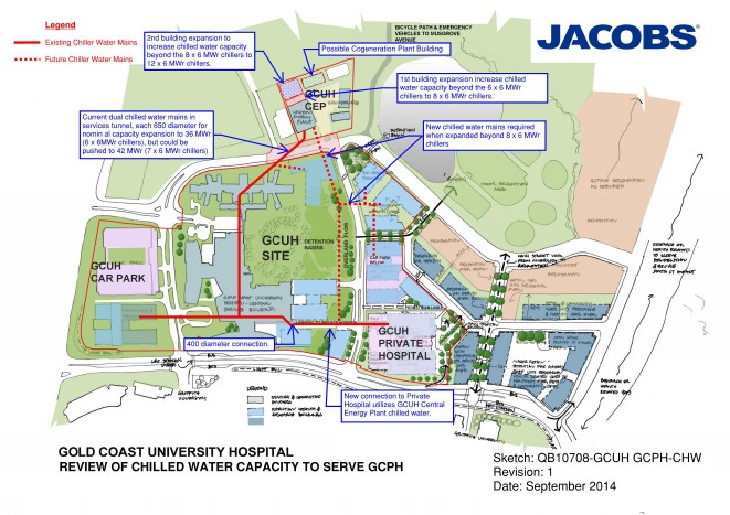
The maximum working load of the existing GCUH is 22.8MWr (based upon assessment of current use and estimated increases when the hospital is at full working capacity) and the maximum working load of the GCPH is assessed to be 3.8MWr. With a required redundancy capacity of n+1 (one spare chiller to allow maintenance as required) and a combined maximum load of 26.6MWr, the requirement is for 6 x 6MWr chillers. This is an increase of 1 from the existing chiller set and these additional works have already been allowed for within the existing plant room.
With the maximum capacities in mind, the specified parameters within which I have been told the heat exchanger must work are as follows:
- 3.8MWr max cooling
- Split of 6^C, entering the heat exchanger on the GCUH side at 6^C and leaving at 12^C
- Approach of either 1/2^C or 1^C, the temperature difference between the outlet temp of the GCPH side vs the inlet temperature of the GCUH side.
So before I contacted suppliers, i calculated the volume flow rate of the loops as follows:
Q = M C ^T
3.8MW = M x 4186j/Kg x 6^C
M = 151 l/s
Other considerations are the pressure drop across the heat exchanger, which will dictate the pumps required, and the pressure of water the heat exchanger must be able to cope with. I have been advised that the pressure drop would be in the region of 50KPa at best and should probably not go much beyond 100KPa. I have assumed the pressure to be in the region of 10Bar as I have no further information at present.
I contacted two suppliers, Alfa Laval and Swep, who provided options as follows:
| Ser | Description | Capacity | Approach | Split | Volume Flow Rate | Pressure Drop | Unit Cost | Quantity | Total Cost |
| MW | °C | °C | l/s | kPa | AUD | AUD | |||
| 1 | SWEP B649 | 4 | 1 | 6 | 160 | 100 | 13265 | 4 | 53060 |
| 2 | SWEP B649 | 4 | 1 | 6 | 160 | 50 | 14720 | 4 | 58880 |
| 3 | SWEP B649 | 4 | 0.5 | 6 | 160 | 13720 | 16 | 219520 | |
| 4 | Alfa Laval HEX | 4 | 1 | 6 | 160 | 100 | 108919 | 1 | 108919 |
| 5 | Alfa Laval HEX | 4 | 1 | 6 | 160 | 100 | 130698 | 1 | 130698 |
| 6 | Alfa Laval HEX | 4 | 0.5 | 6 | 160 | 224427 | 1 | 224427 |
Conclusion
Whilst the use of a heat exchanger simplifies maintenance ownership issues between the two hospitals, and the separate chilled water loops provide an element of isolation should there be any problems on the GCPH loop, that comes at significant cost.
The system would require additional pumps, again with an n+1 redundancy, to pump the water through the GCUH side of the heat exchanger, whereas if the chilled water is connected directly there is only one pump set required to service the branch.

The capital cost of the heat exchanger itself can be seen in the table above and is significant, added to that is the requirement for additional pumps to serve the GCPH side of the exchanger as shown in the diagram below. These pumps also have significant capital cost and there are also the associated maintenance costs to consider. There is also the added issue of having to house the heat exchanger and pumps somewhere within the GCPH.
Based upon these factors, I cannot see how the use of a heat exchanger could be considered a viable option, but at this stage I have just been tasked to source options. I will discuss with the PM as to the way forward.

Ben
Any idea what is driving the need to consider using the heat exchanger? Has somebody identified potential liabilities that may be contractually tricky to apportion to one party or the other?
Jim
Ben
I suppose the separation of the two circuits has been justified somewhere along the line and is understandable given the functions of the two hospitals. This is looks like a typical district schemes so the liability for maintenance and repair can be shared by applying a suitable tariff for usage.
Where did the operating parameters come from? What is the imperative?
From your sketch it looks like you are considering a parallel flow configuration did you consider counterflow?
Mark