Starting with Laing O’Rourke in London, another muddy hole!
Overview. I am working on a Laing O’Rourke project near Elephant and Castle Station. The site previously consisted of an 8-storey office block which was mostly demolished prior to site handover. It included a one-storey basement and therefore the start state for this project is at one storey below ground level. The project endstate is the erection a 40-storey residential tower complete with two basement levels, along with a separate office development of eight storeys.
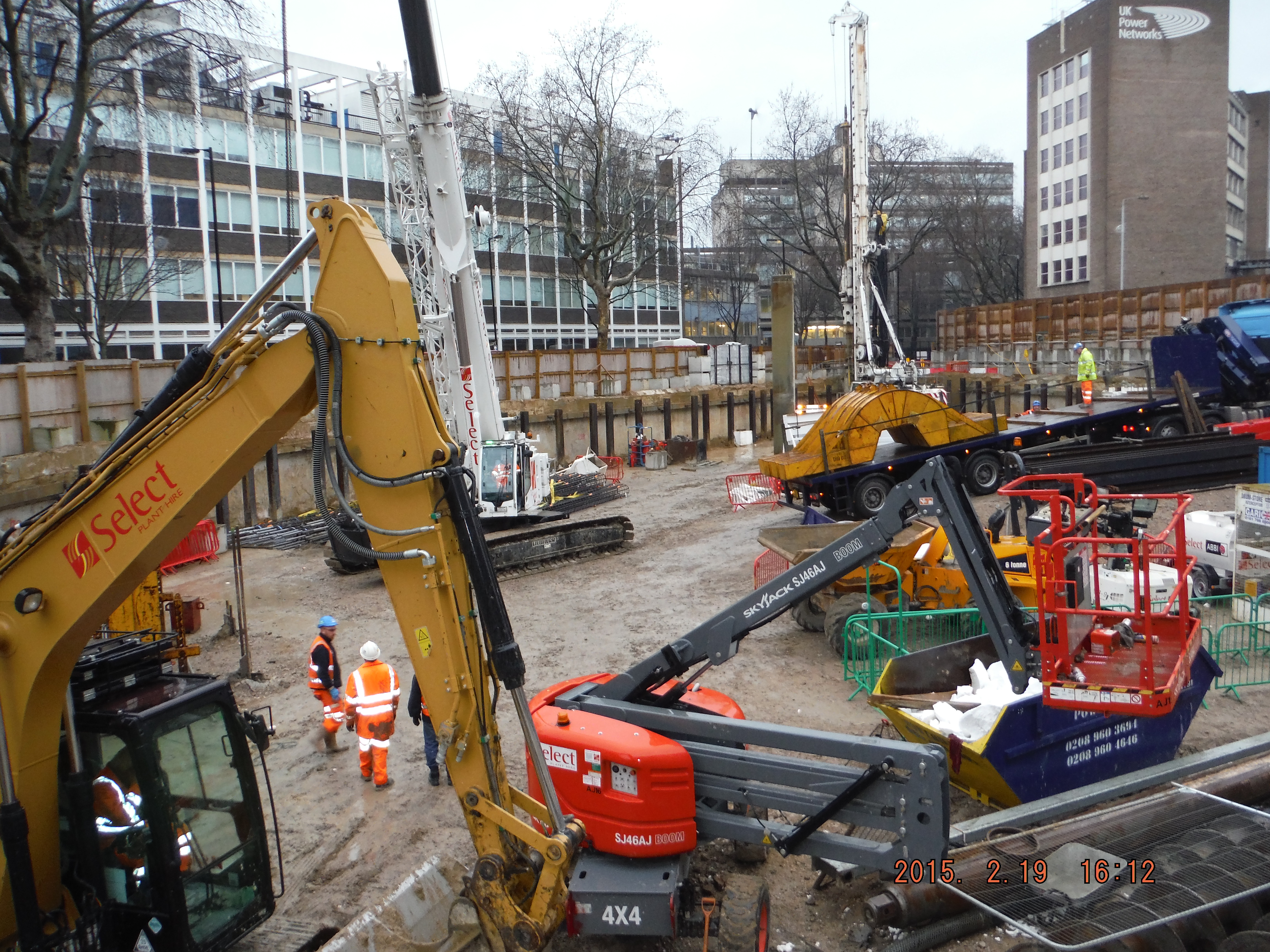
The existing (confined) site
Contract. The project is currently running on a Letter of Intent to achieve enabling works which comprise of the secant pile wall and capping beam, construction of part of the bearing piles, realignment of mechanical and electrical utilities and demolition of an existing sub-station. These works total £4.4M with a provisional sum of £1.1M to effectively close the project if the subsequent superstructure contract is not approved. The enabling works would give a future developer opportunity to construct something of their design, hence making the site attractive to other investors. This staged approach also gives the client time to ensure the remaining programme to build the tower meets their time and cost drivers. Quality is also important, but the balance is very much cost, then time and quality.
Pile load test. The design of load bearing piles for the tower will be finalised based on the results from the static load test that was carried out this week. The soil profile is generally 7m of river terrace deposits, 20m of London clay and then a deeper band of Lambeth Bed sands. Toeing into the sand (circa 30m pile length) will give the end bearing resistance needed but the number of piles will be determined from analysis of the load bearing test. Having heard John bang on about these types of soils I have now seen them and a static load bearing test rig in action – all making sense.
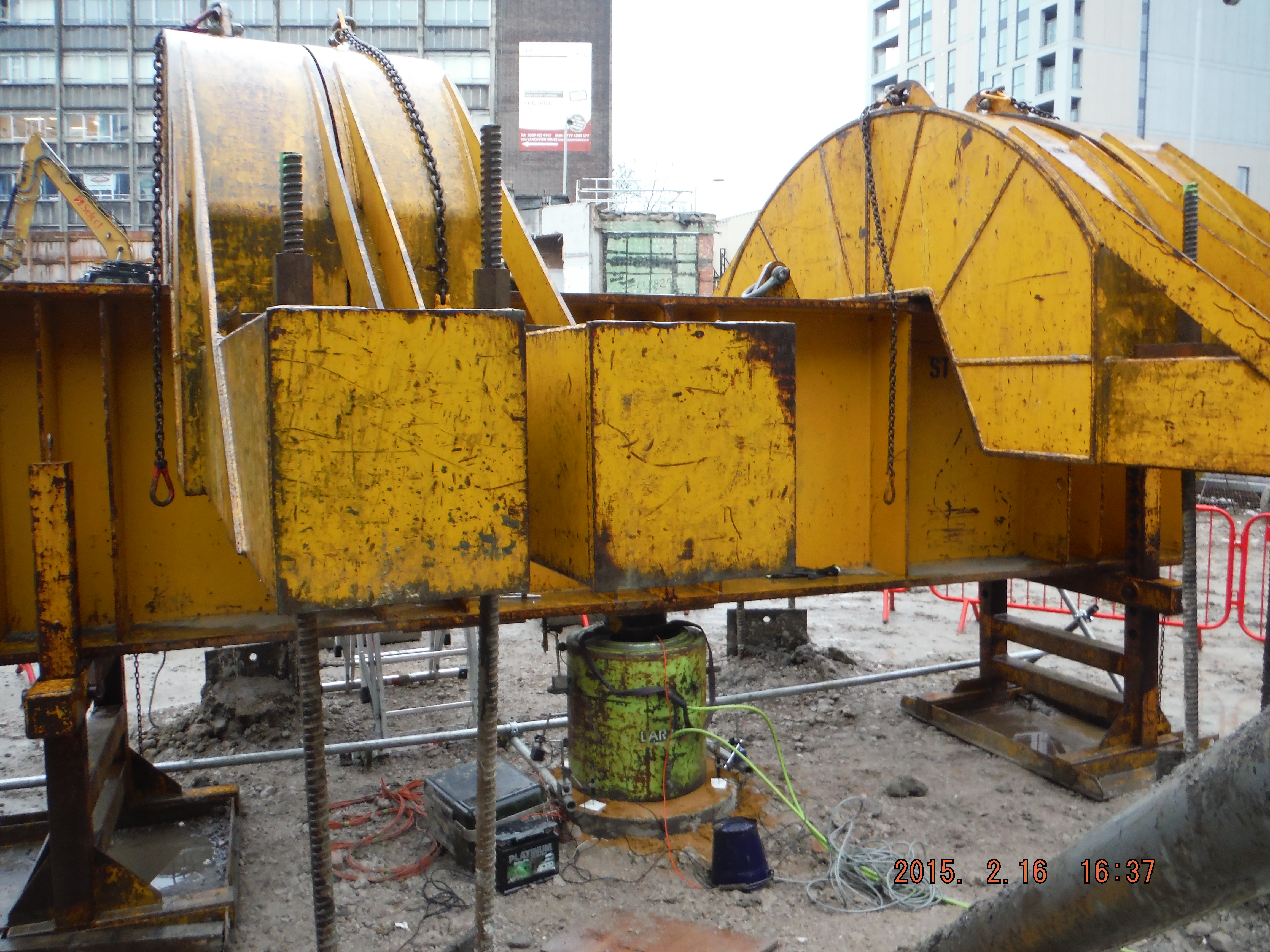
Pile load test. Test to 10MN or 75mm settlement.
There are two proposals for the load bearing piles:
- Individual large diameter piles (41no 1500mm diameter rotary under bentonite)
- Raft foundation (comprising 124no 750mm CFA piles).
The confined nature of the site means the bentonite option is not preferred because the amount of equipment would mean little else could happen concurrently onsite. Therefore the raft option is likely to be adopted, notwithstanding the outcome of the load bearing test, although it will mean excavation around the piles is pretty tight.
Sustainability. Laing O’Rourke are keen to demonstrate adoption of the Construction Logistics and Cycle Safety (CLOCS) initiative. It was brought home as I read an article in the Evening Standard which talked about the death of a cyclist after being hit by a HGV yesterday

Evening Standard reporting of cyclist death
The statistics point to HGVs being responsible for a high proportion of accidents considering their number compared to other road users. Furthermore, the HGVs were often construction vehicles such as tippers or mixers. I then picked up the NCE magazine to is see an article on “Cyclists’ safety is now critical”. There are levels of adoption of CLOCS going from using CLOCS compliant supply companies (see photo below of tipper with side protection rails and warning signage) to running Construction/Cycle days where cyclists can come and get a mini bike service and have a chat about cycle safety. The question is how is this best achieved on this site to show adoption of the scheme, especially as the site is adjacent to one of Boris’s cycle superhighways.
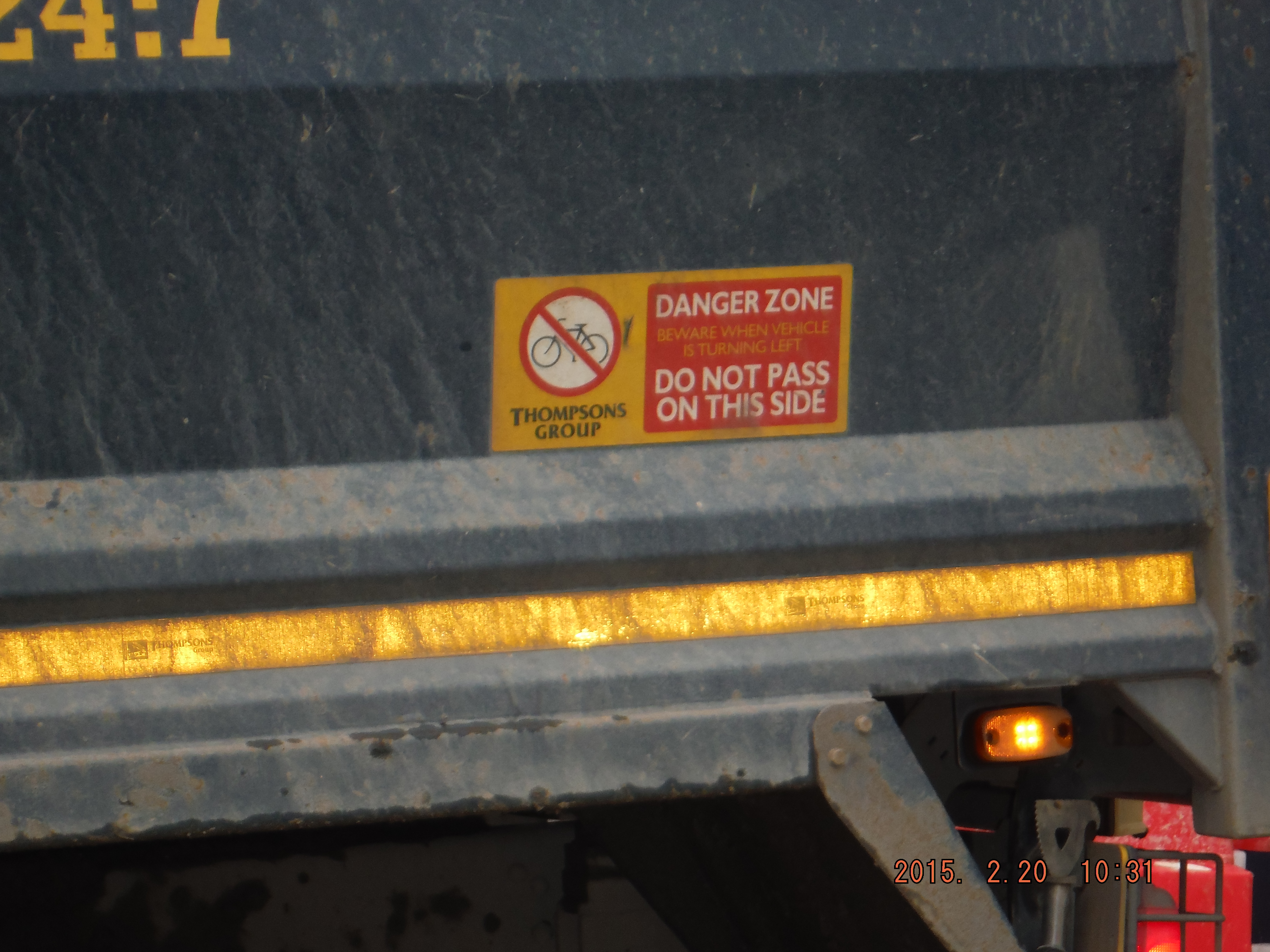
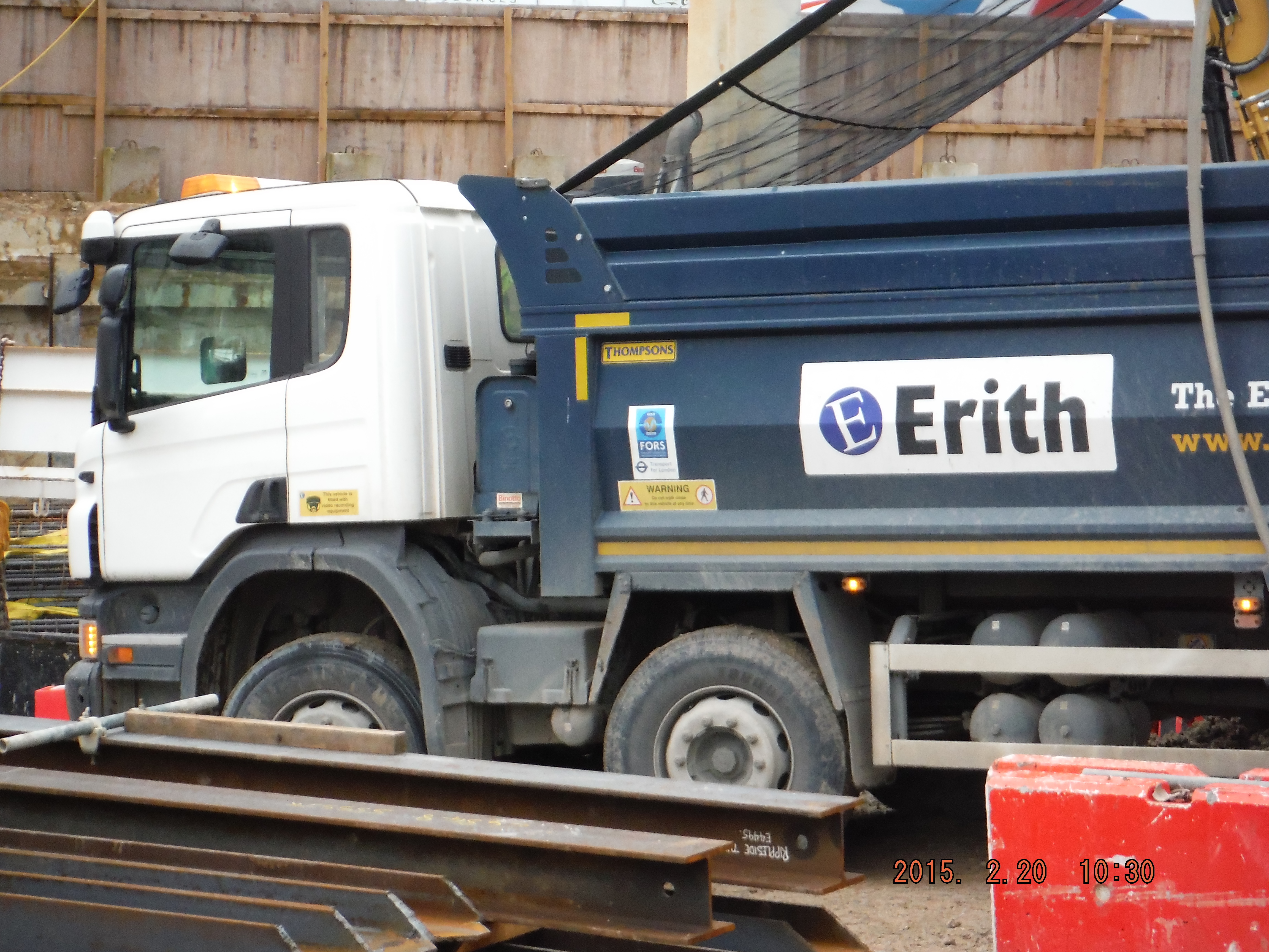
CLOCS Compliant tipper vehicle on site
The digital age. At this stage of the project the understanding of how best to implement BIM and realise the benefits of digital engineering is yet to be determined. There have been some point cloud (3D image survey) productions of the site (see below) but how this can be advanced is being established. The Laing O’Rourke Leadenhall Project (Cheesegrater) modelled the construction process of the whole building to refine the method in order to make it more efficient. Other advantages of digital engineering include cost and time savings by being able to demonstrate exactly what is required and the sequence in which the works would need to be carried out. At a more refined level, 3D modelling of reinforcement in the capping beam is an area which is likely to be explored due to the variation along the length of it on this particular site, not to replace drawings but to be used alongside them. The capping beam is an area I am to be responsible for so more to follow.
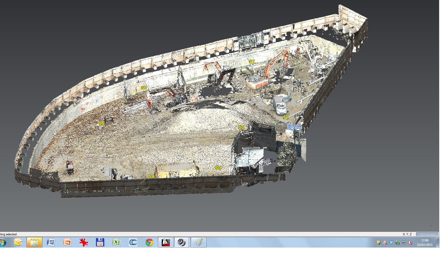
Point Cloud Survey of the site.

Damnian
What were the tension piles in the pile test? Are you only doing one?
Regards
We’ll have to chat pile testing, I’ve got some of that going on this week.
Have they blinded that ramp yet? Our’s is definitely paying off.
It’ll be interesting to see how the raft option works it’s way around utilities and drainage. BIM will no doubt cure this with ease…
I’m guessing that they’re using the maintained load test for design verification. Do you know what the testing strategy is after the MLT is finished? Are there plans to do any working tests? The number of tests is normally related to the type of piling (and the experience of the crew) and how much is know about the site conditions. This gives a risk category for the work which then should lead to the number and type of tests undertaken on the project. For low risk sites its suggested to have 1 prelim test pile per 500 piles and/or 1 working test pile per 100 piles. How many piles are there going to be in total on the site?
Hi Neil – All piles were 750mm CFA piles to 26m depth (passing through 6m of river terrace deposits, ~16m London clay and 4m into Lambeth sand).
Richard – Good point regarding drainage – one for me to follow up on.
Pete – Yes it was a maintained load test but used to determine number of piles. The results (although I am yet to see them) have thrown up quite a few questions. Depth required (typically the one pile rig on site has a maximum depth of 28m so hopefuly we do not need to go any deeper), diameter and number of piles required for the raft. From memory the raft has about 100 piles plus a number of 3-pile pile groups. I will ask about working tests as it would make sense for there to be some.
This is all to avoid construction of 1500mm piles under bentonite so it will be interesting to see the final outcome.