Site Two Fifty One – Uncertainty in Ground Conditions
On Wednesday, the first ground bearing CFA pile was drilled. The stratum is made of 7m of river terrace deposits (sand and gravel) then 19m of London Clay. The auger was drilled to a depth of 24m and on extraction the nozzle at the base of the auger was found to have been blocked (reasons are extensive – poorly primed hoses, gravel getting stuck within the bottom of the auger, but not the focus of attention here).
On removal of the auger the gravel began to “flight” which is where the size of the hole increases in relation to the bore diameter. This is a particularly prevalent problem in sands and gravels. Add in a water table at about 1m depth and that compounds the problem.
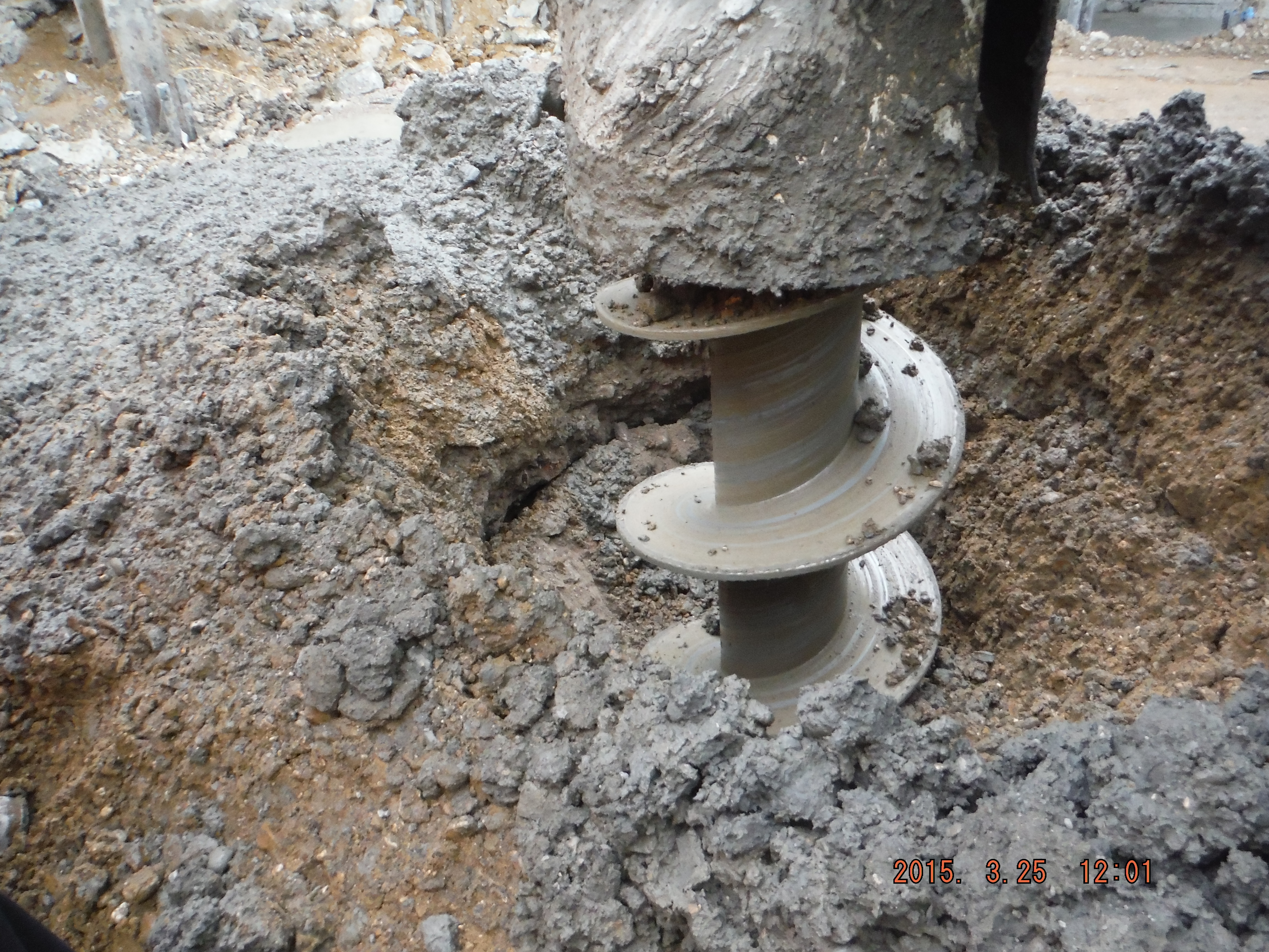
Pile diameter much greater than auger diameter
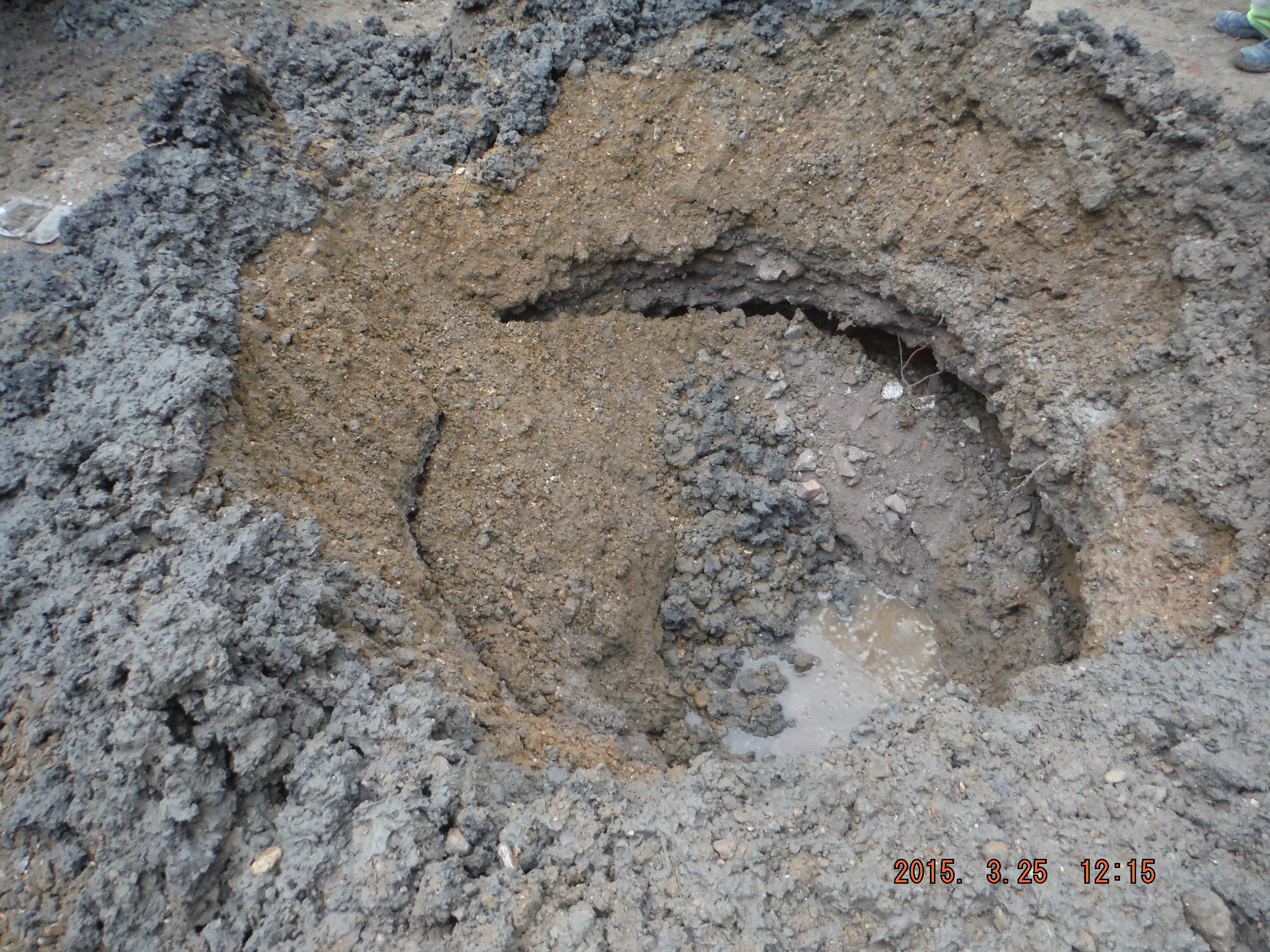
Pleasingly my pile mattress was doing a good job at holding the pile rig up. Less pleasingly was the undermining occurring below it potentially causing diffemderential settlement and risk of the rig turning over.
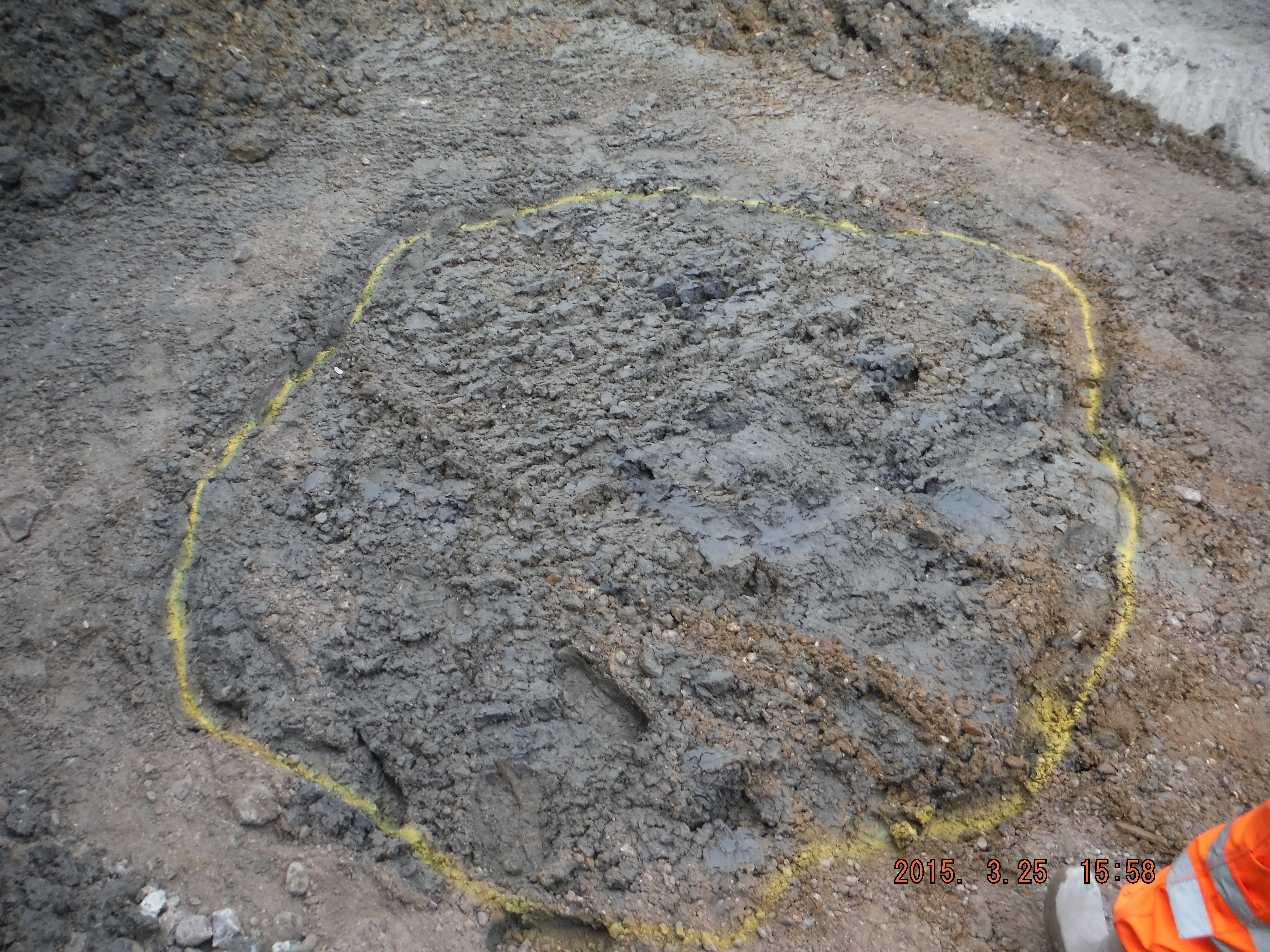
Hole diameter increased 4 times original.
Take 2. The next ground bearing pile was approached in the same way. Auger goes in, no blockage, concrete comes out and auger extracted. Nice vertical concrete pile. Then the reinforcement cage was added then it was pushed into the pile with an 8.5m column to sit the cage at the right cut-off level. This was in order to avoid breaking down the pile with reinforcement in. Everything great.
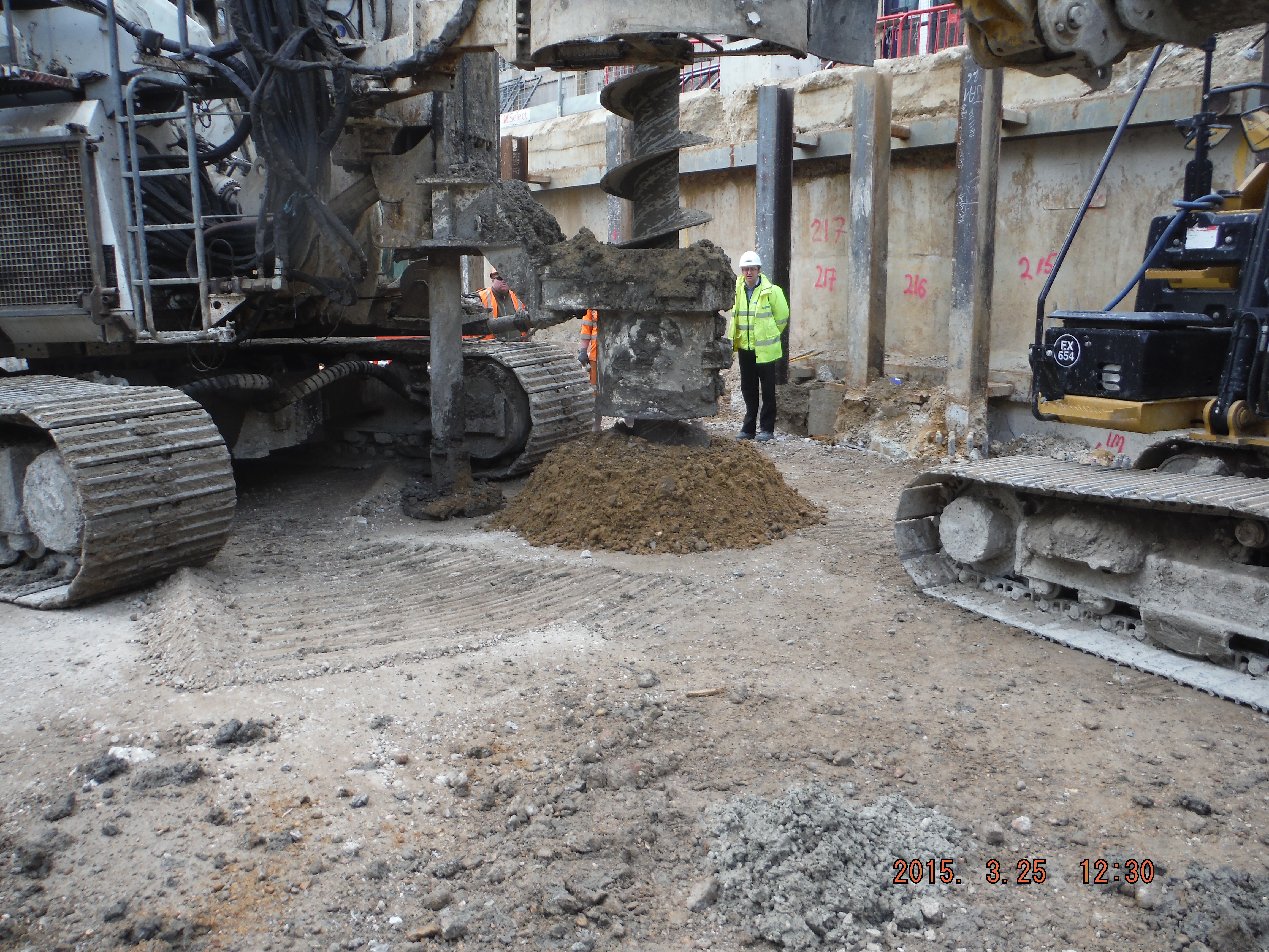
Pile rig mast toe not being undermined.
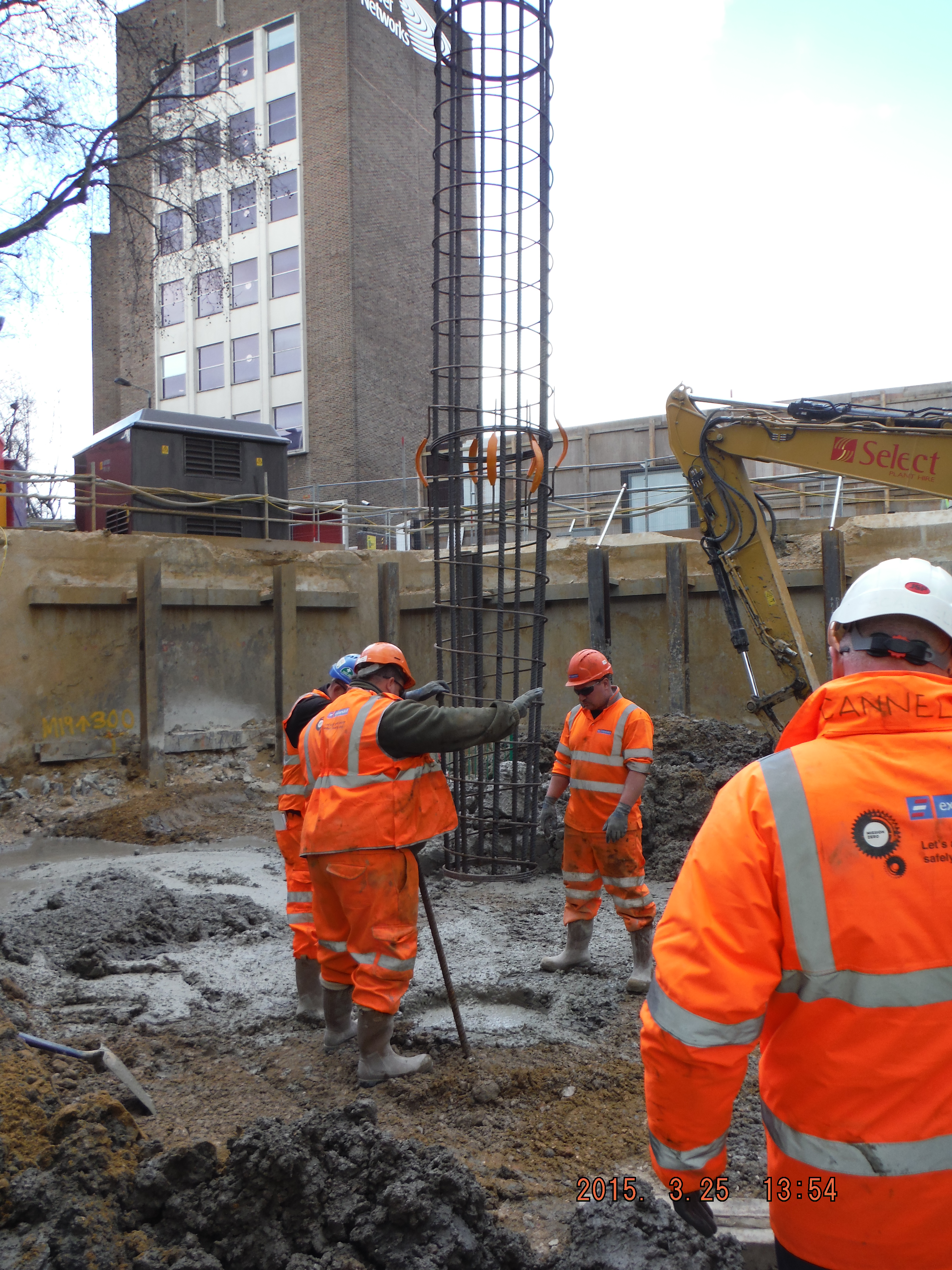
Reinforcement cage being lowered into pile hole 750mm diameter
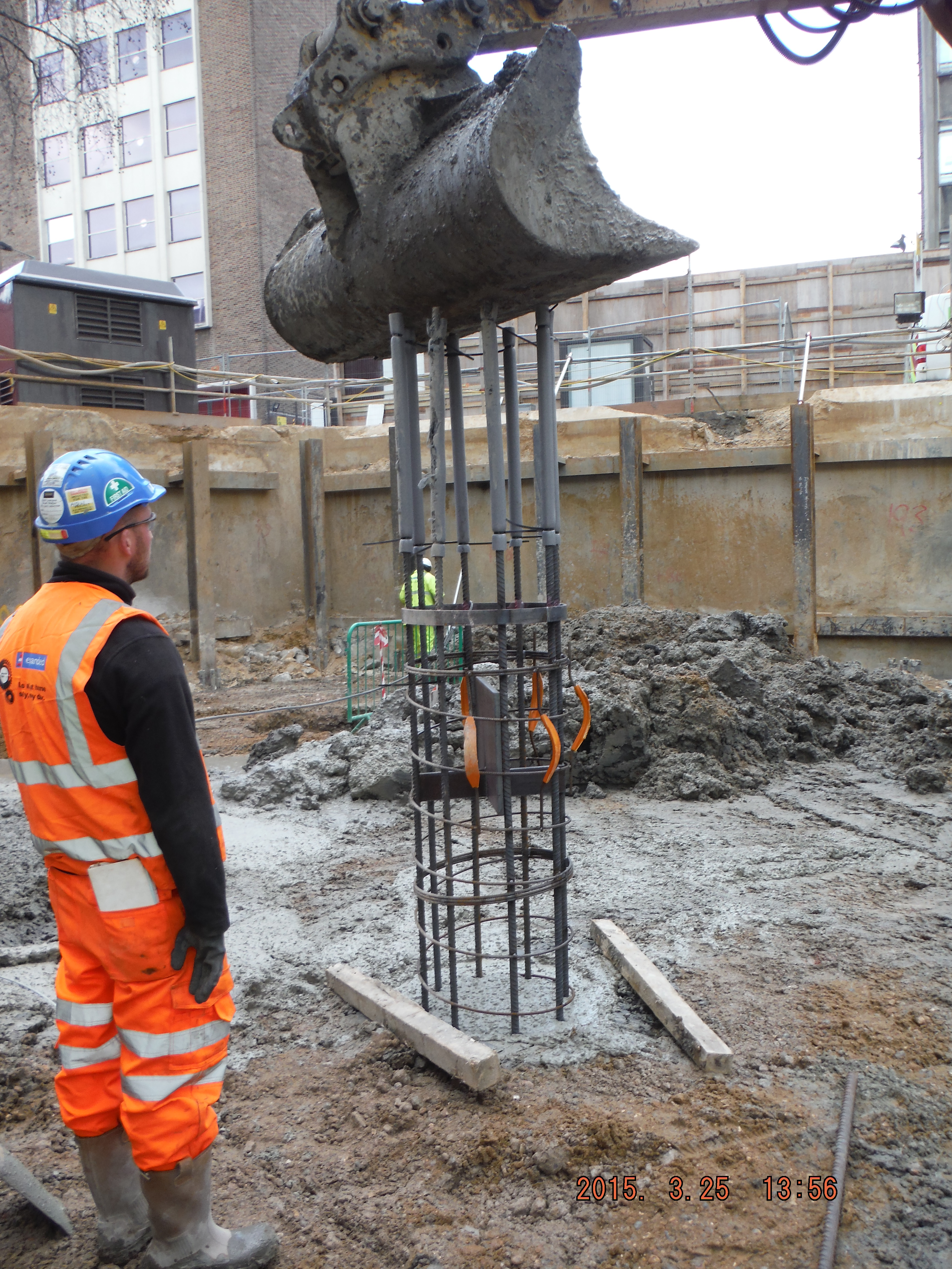
Cage plunged firstly with excavator bucket
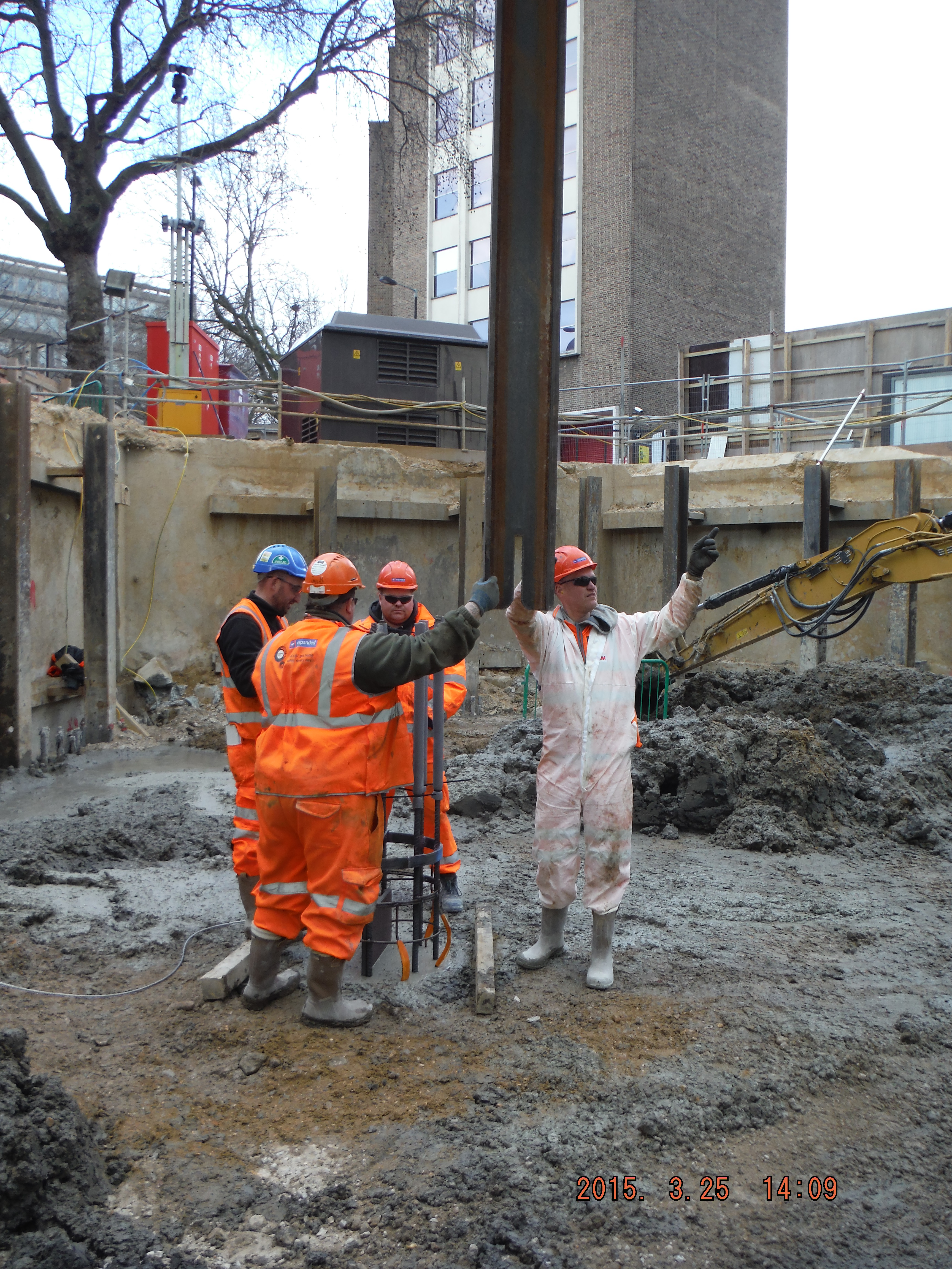
Cage plunged secondly with an 8.5m RSJ

Steel wire rope used to stop the reinforcement cage from embedding any further into the pile.
Take 3. Auger is drilled in and at about 20m embedment the extracted material from the pile drops into the ground. The foot at the bottom of the pile rig mast was starting to get undermined and so the drilling was stopped and the auger retrieved.
With John Moran’s prompting, he directed me to the ICE Specification for Piling. There is a section on CFA piling in ground with a loose section overlaying a stiff clay layer – see below in Option 1.
Solutions
Option 1.
Reduce the auger rotation in relation to penetration. I.e. reduce the auger turning speed or increase the rate of penetration. There must be some flighting (or extraction of material) to avoid corkscrewing the auger into the ground which would then be impossible to retrieve.
The specification says where there is high ground water there is higher risk of over fighting and so casing the piles should be considered.
Option 2.
We have just reconfigured the pile rig from cased rotary bored to CFA because it enables the deeper piles to be installed in the Lambeth Group below the London clay. So changing back to Cased is not likely to happen. Additionally the combined case and CFA rig that Laing O’Rourke own only drills to 17m.
Option 3 – chosen option.
Surcharge the loose ground around the auger with dry material. This should then stop any displacement of material around the pile mast. Turns out this is pretty effective! 4 piles done on Thursday and 4 on Friday.
Why does this work? I will attempt to speak in effective stress language. I think this is nothing more than a case of the quick condition, recently spoken about by Guz. As the auger penetrates through the Gravel it unloads the ground (simply by extraction of material by the auger). With the high water table, and the reduction in total stress, the augering results in the effective stress (Terzaghi : σ’ = σ – u) reducing to zero, i.e. piping. Hence, this causes the ground around the hole to fall inwards. So by adding additional total stress (surcharge) it maintains a positive effective stress and stops the ground from collapsing. So now piling can continue.

Damian
That’s what I heard as well from the office over the way – well done
Kind Regards
Nice one mate. Over what sort of area are you applying the surcharge? And what the effect when you take it off again?
I blindly believed what the proposed drawing said and blogged about the use of 40m CFA across the river, I was wrong. I was looking through Johns notes and noticed that CFA max depth is 30m, when I questioned this I got a blank look and a phone call later it was confirmed that it was a planning proposal and the actual piles will be bored. We await the actual design however we are using CFA piles on the rail bridge.
What was the make up of your piling mat? How close together are the piles? Did the undermining below the piling mat affect your ability to construct other local piles?
🙂 How di you apply and maintain a watch on the surcharge?
First question is, how do I get automatic updates when there are comments!
Hi Neil – Yes I had to refer back to PEW for some support on the issue!
Guz – The surcharge is simply some 6F2 and dry sand/gravel stored near to the piling location with an attendant excavator to load up the ground next to the pile when/if the ground drops. If the ground does settle, the stone is pushed onto the area (up to 3m diameter) by the excavator until the pile is completed. It’s difficult to see what happens when the auger is retrieved from the ground because concrete goes everywhere (as it should) and clearly there is lots of water involved making one big soggy mess, albeit with an intact pile and pile mattress. Once a pile has been finished and the area scraped clear of concrete/clay/slush debris the 6F2 is then reapplied and compacted to re-form the pile mattress.
Olly – If you are doing bored piles in water you will have to pump the case prior to concreting. What is the case toeing into – if permeable layer, how will you stop the hydraulic gradient pulling more water into the case? Pile mat is 400mm thick, 2 layers 150mm and 5 passes, 1 layer 100mm, 5 passes. 5mm settlement under plate bearing test of 552kN. Pile order is such that adjacent piles are not done on the same day. Not because of the undermining issue but because of disrupting an un-cured/green pile so close. We keep about 4-5m between pile centres on 1 day’s piling. If it is the secant wall, then about 4 piles (3m) between centres.
Richard – surcharge applied with 6F2 with pile supervisor checking. As long as the spoil extracted from the pile in the sand/gravel horizon is replaced by same mass of 6F2 then all seems to be well. Then again, sometimes the surcharge is needed other times not – and that is the variability in the ground conditions, specifically ground water.
Right, now for the drainage scheme to drain this bath!
Damo – Our ground is 2m Alluvium, 2-6m Gravelly Sand and then in to Gault Clay. The deepest pile is 39m and the shortest 35m so all of them are toeing into the clay…we think. The major GW risk is associated with the sand and this section of the pile will be cased. The plan is to have enough casing on site to go to max depth however the first few piles under the abutment will be used to test condition with a hope that we will only have to case a few meters in to the clay. A 150mm suction pipe will be used to dewater any seepage prior to adding the concrete with a tremie. The piling forman is confident that any remaining water will rise and be flushed out of the top by the concrete.