Site Two Fifty One – In the thick of It
Site Two Fifty One – In the Thick of It.

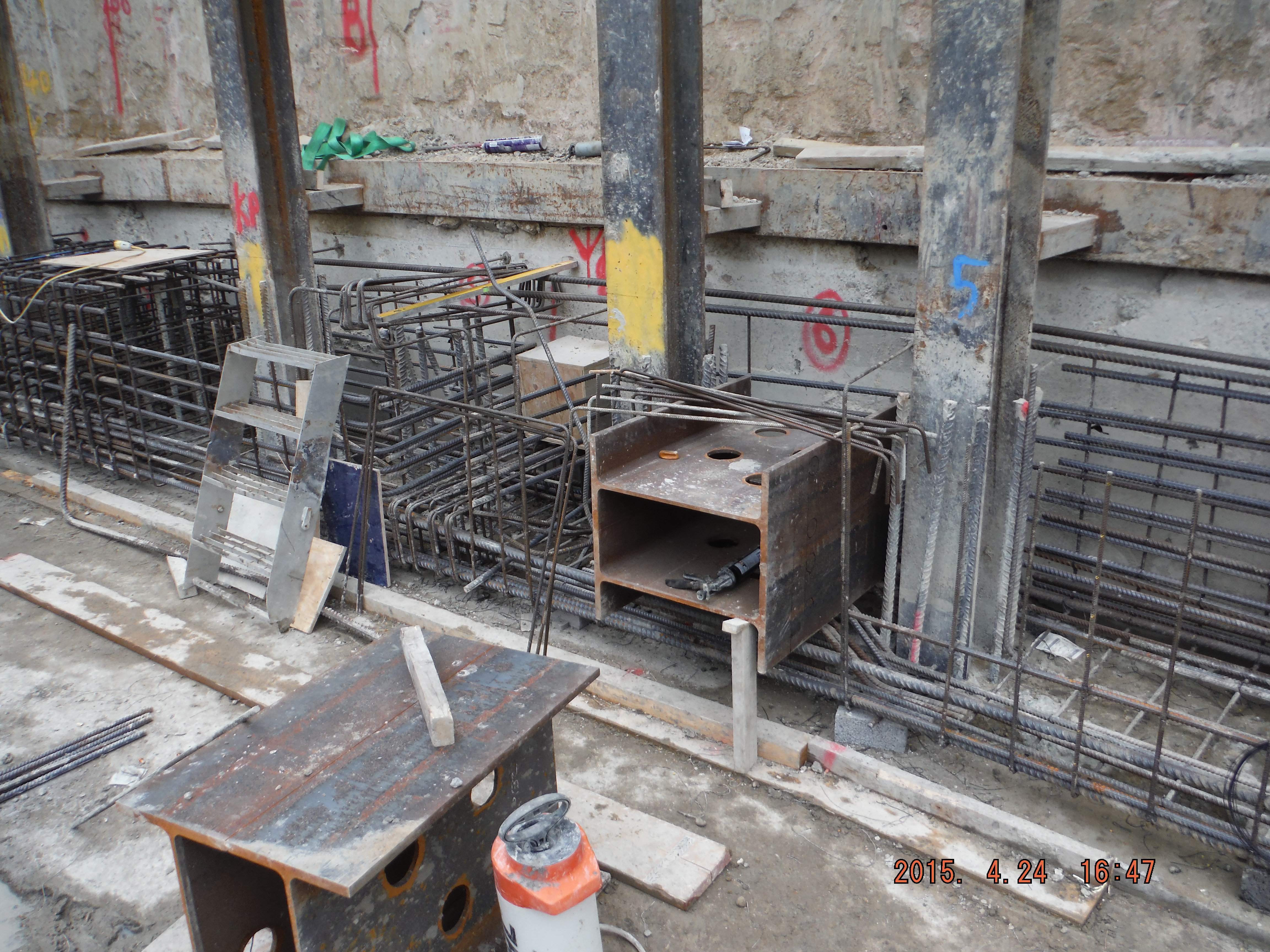
Capping beam steel erection.
I have mentioned before that one of my roles is the installation of the capping beam which runs the full perimeter of my site (180m). The steel for the first 35m arrived on Monday to culminate a design development of something I have been responsible for since arrival. The capping beam will have an in-situ wall sitting on it and a basement slab spanning from it. Additionally, for about 5 months, it will be used as a beam to prop off in order to excavate one storey down.
Groundforce propping plan (click to open pdf): 1728 101
So there are elements to the installation which have huge consequences if not correct.
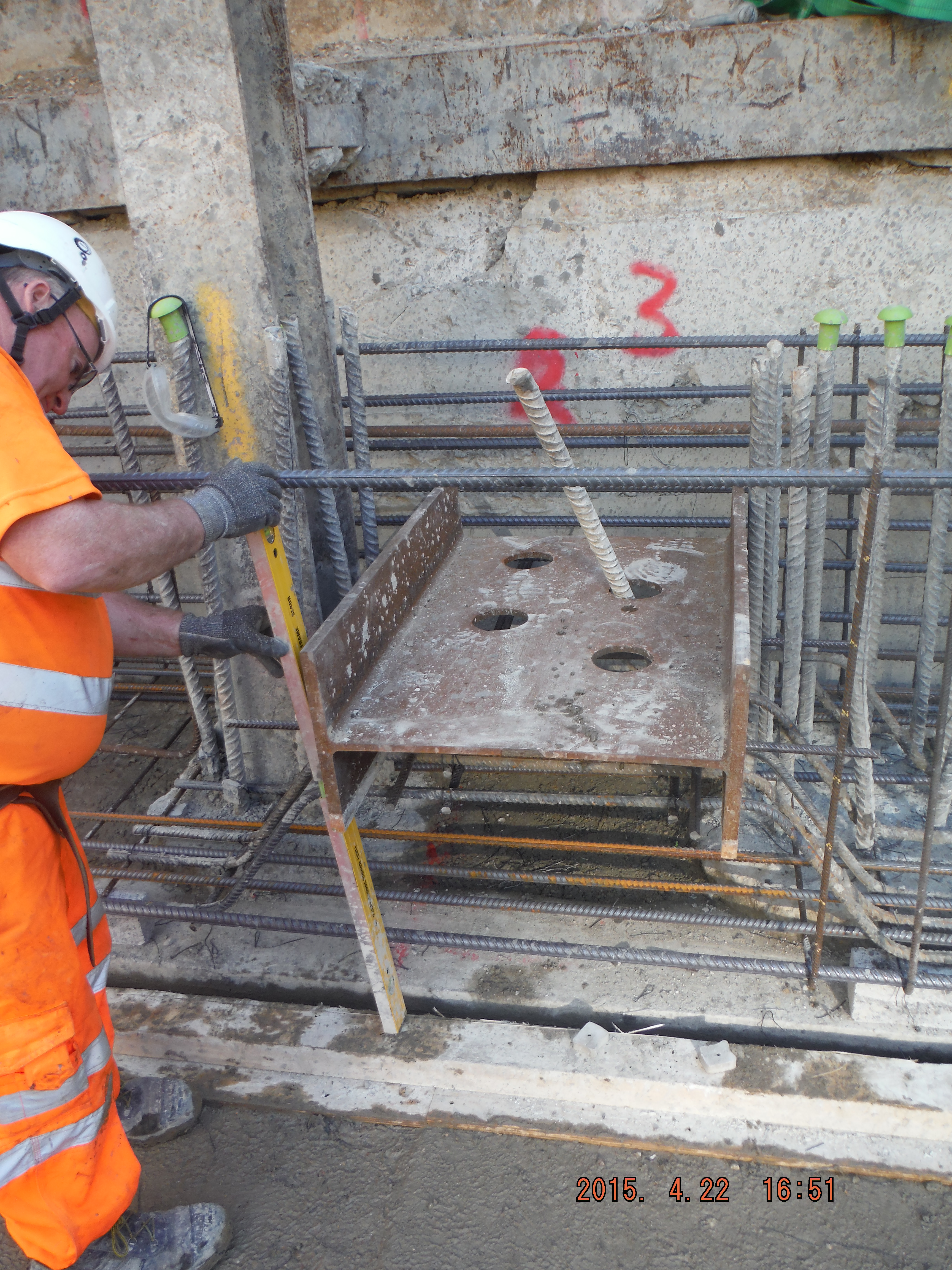
Single shear stub.
Double shear stub.
There is a drainage duct which protrudes through the beam and there are umpteen ‘king posts’ column sections retaining the old retaining wall behind.


Drainage pipe location (left). Bent bars around drainage position (right).
All in all, there is lots going on. The capping beam steel has been digitally modelled, which has 2 advantages. 1. It helps understand how it fits together and 2. The steel schedules are produced from it (Tekla software) which can be used directly by the steel supplier, rather than a person re-typing a pdf document.
As a task, perhaps initially seemingly pretty minor, there are actually numerous considerations:
- Sourcing of steel (Laing O’Rourke will only purchase from Europe although many steel suppliers source from China because it’s cheaper).
- Delivery method: pre-slung or stacked for slinging on site. Method of lifting (crane, excavator), LOAFs.
- Length of bars for working in congested areas (more lapping versus ease of installation).
- Stop ends (max pour size is 40m3.) Use of hirib to avoid scabbling.
- Prop end plate locations and bolt hole positions.
- Formwork design (yes concrete pressures for a 1.2 high beam is important).
- Resource management (lead times, timber, concrete, steel, tools and equipment)
- Concrete – waterproofing.
- Future slab starter bars (kwika-strip).
- Labour management (steel fixers, carpenters, labourers).
- Dewatering (bottom of blinding is at ground water level): sump pumps, discharge permits, siltbusters.
- Concurrent adjacent activities: sheet piling, CFA piling, muck away, welfare establishment, ramp movement).
Reflections.
So far so good, just. It is pretty much construction by just in time design. This means I am getting drawings hours (sometimes minutes) before they are needed on site. This means being familiar with bar mark notation, real detail in why shear links are here or there is key. In reality there are good people to answer my RFIs (temporary works department, Groundforce shorco, digital engineers, steel supplier (Midland Steel), the designers (Waterman)) but there are always pressures to deal with on site. Line and level of shear stubs for props, drainage duct location and invert levels and actual position of the capping beam itself.
It is hugely rewarding to see something you have been involved in start come to fruition, albeit the first big test will be my shuttering design! The concrete pour is planned for next week so no doubt the grey stuff will soon feature.
I think running the execution of the capping beam is a great chance to learn how things work before the significant challenge of the basement slab (entire site) comes along.
In other news, there has been the first working load test on the office piles and a section of site has had sheet piles installed to act as a replacement retaining wall (where the old substation was).

Pile working load test (as Pete predicted!). No further details yet.
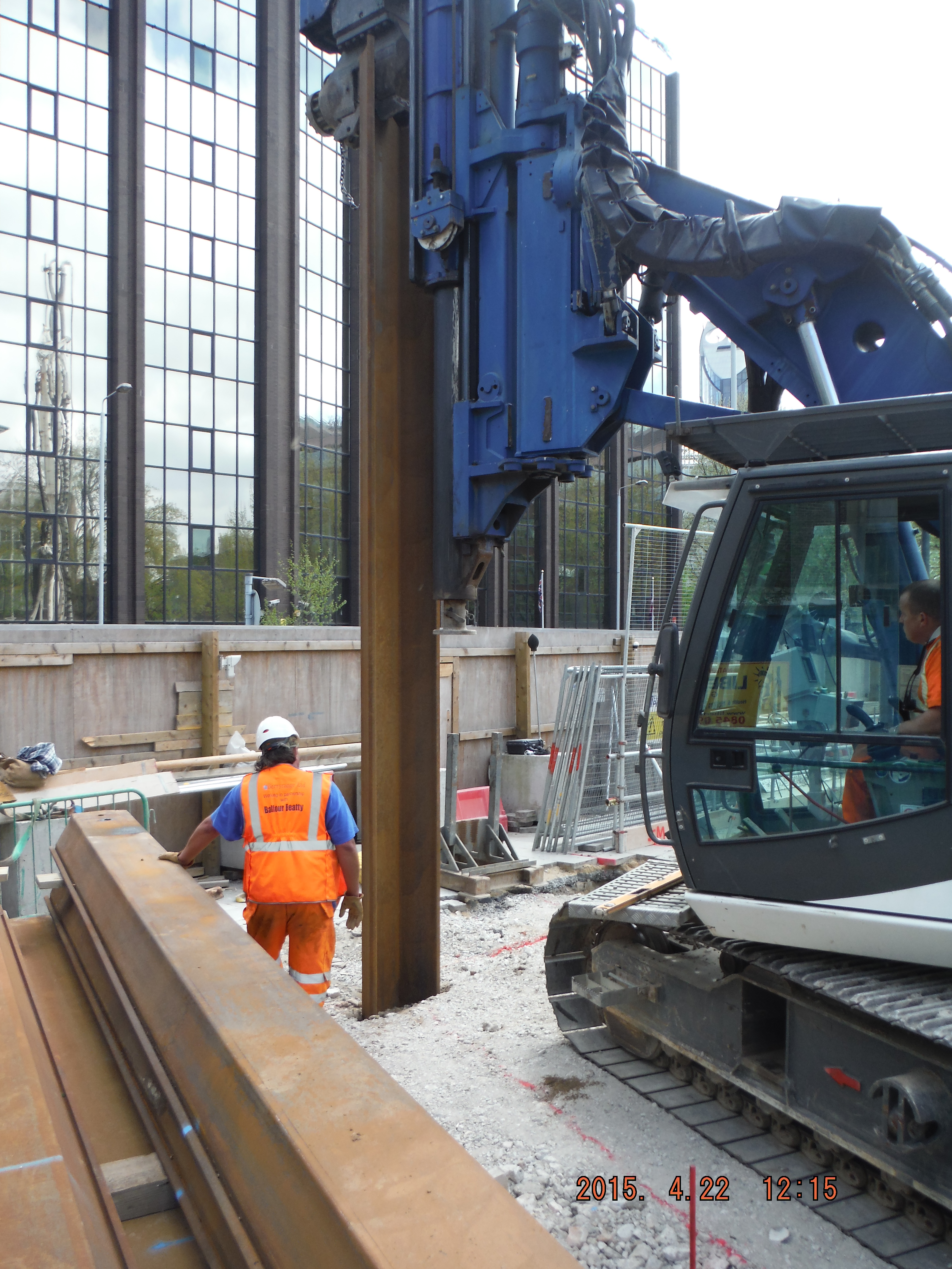
Rotary bored (tick), CFA (tick) and now a bit of vibratory sheet piling.

Why’s your maximum pour size so small? It’s not all about size obviously, but I assume that won’t apply to slabs and the like?
Guz – straying into the unknown to answer this but I am hoping Richard will correct me.
The Specification (based on the National Structural Concrete Specification for Building Construction) gives maximum pour sizes depending on structural element (wall or slab) which varies with waterproofing requirements or end restraint type. The reason is for thermal and shrinkage effects – i.e. the point is to limit crack size. Hence a large area of slab (thin) is possible, compared to a thick beam (1.2 by 1.2m in my case). I suspect a very deep slab (such as a basement slab) may require a greater number of construction joints to avoid thermal effects causing shrinkage and therefore cracking. My capping beam is required to be water retaining and so greater restriction is on it (crack width control). As always, there is scope to increase the size of pour (albeit 40m3 is about enough anyway) but this would need justification and probably mitigation measures (such as waterproof additives). Interestingly the Specification does not require testing of any concrete (although we will do some) and therefore how we will know if we have achieved the specified crack width (maximum of 0.2mm) (or compressive strength) is a little unknown!
I’ve just had a look in the NSCS and we are totally ignoring that! I asked my CEng and his comment was “there must be some sort of allowance for big basement raft slabs. Its only a guide anyway”! Classic!
I’ve checked the guidance notes, it’s fine.
I see what Guz is saying about your pour size, to mitigate part of the risk on my site we used (a lot of) thermal monitoring on all of the large pours. The very rough rule of thumb from CIRIA 660 Early age thermal crack control in concrete (a cracking read…) is to keep the temperature in the centre of your element below 70 degrees and to limit the differential temperature to 25 degrees.
Whats the hirib that you mentioned to avoid scabbling? Is that a surface retarder similar to rugasol by Sika? Remember that the surface will still need to be greencut within (approx) 24hrs. [greencut = pressure wash]. If the application of the retarder wasn’t done properly then you may still need to scabble the surface. Are you using a spray on curing agent?
Pete, measuring the thermal gradient monitors issues and is useful for QA but doesn’t mitigate risk unless you can react in real time (e.g. adjust an internal cooling system). I’ll let Damian tell you about Hirib. essentially mechanical means avoids the need to cut back through retarders and cusing agents before continuing a pour. If you don’t cut back agents like rugasol thoroughly they can provide concrete quality/cold joint issues of the nature that they are designed to mitigate. Did you need to scabble back much after using them? If so did you get to see the effect of the retarder on the concrete quality?
Interesting Proping drawing. Note that the prop No. 4 ‘southern’ end at grid G4 (or similar) is 36m long and meets the wall at over 40degrees but is only on a single shear connector, others at 20 degrees require a double yet all are spaced at about 10m and probable carry similar stress (?) – bit of a surprise? The inclusion of a Health and Safety CDM box is great – shame about the content! Presumably hydraulic props have no pressurised fluids risks and ther are no specific to site risks with this design…
I expect your specification does require testing of concrete through reference to other documents (BS13670 and the pour plan). Early thermal cracking is usually controlled through mix design, specification, reinforcement density and curing regime. It is an issue in elements that have high volume and ‘odd’ outstands i.e. deep wide bases with walls. In long elements such as your ground beam it is normal to cast in limited lengths, often as hit and miss sections (but sequentially if matters are very sensitive). Usually 5m is considered the normal crack spacing if not controlled so this would be the section lengths. 40 cubic metres is going to give a 35m length in one run so I hope that there has been more thought given to cracking than I have here!
The treatment of shear connectors and box outs in relation to longitudinal steel is interesting. Is there a design need to carry moment accross these locations and, if so, how is it being achieved?
Hi Richard,
Thanks for your observations on the propping plan. Regarding CDM box – Agree high pressure hydraulic fluid is a hazard. It is highlighted in the risk assessment as: “Pressurised fluid release – Inspect all fittings and hoses prior to use for any signs of damage or wear and replace if damage or wear is identified” so mentioned although a little light on the detail.
Regarding prop loads, angles and shear forces, a single stub is for forces up to 1200kN and a double stub anything greater than 1200kN up to 2400kN. You highlight prop 4 as being surprising to only have a single stub. The prop load is 1140kN, so pretty close to being a double. The corner point at e1 also acts as a prop and so the actual load in the prop is visually less than it appears due to the “corner” taking a proportion of the load between e4 and e1. Additionally, the corner is likely to attract more load due to its stiffness being higher than that of the prop.
In short – a very educated look at “what are the risks?”, which I had not applied to it so thank you for pointing it out! Perhaps standing back and taking a more holistic approach might be sensible.