Archive
No engineering.
For anyone interested in professional engineering content read no further. This blog from myself will not deal with life on site, but is a random tangent of life living as a member of the military in London.
This week on the way home from work I popped into a local take-away (for the first time). Whilst waiting I couldn’t help but over hear three young men complaining about the state of British foreign politics, the theft of other countries resources and the fact they were under constant surveillance from the security services. At this point I should have probably decided to wait for my lamb kofta and walk out of the door. I didn’t. I decided to try and engage with the three young men, to find out why they held the beliefs that they did and possibly have a reasoned conversation / debate surrounding the issues. Unfortunately this didn’t occur; I was confronted by a stonewall. I became slightly hopeful when one of the three mentioned that his thoughts were part of a thesis and who was I to question it? Perhaps it would be peer reviewed and I could read it on publication? No. It wasn’t that kind of thesis. In the end I did have a reasoned conversation, but with a bystander, which was very positive. Having concluded my conversation I left the three young men to enjoy the rest of their evening. When I left them they were still certain that they were being pursued by the security services, that the UK’s aim was to de-stabilise the world and that the September 11th disaster was a conspiracy theory.
The area in which I had this conversation was Kingston. The average house price is well over £500,000 and the borough has previously been classified as the third least deprived borough in London. The individuals I had the conversation with were articulate in their responses. I suppose my questions and concerns with regards to this encounter are: why do people in such a privileged area hate the country they are from (although acknowledging they themselves may not be privileged) and at what point should such a hatred become a concern with respect to security. How can they be engaged? It’s certainly not by a random chap having a chat in a kebab shop!
The invention of looking
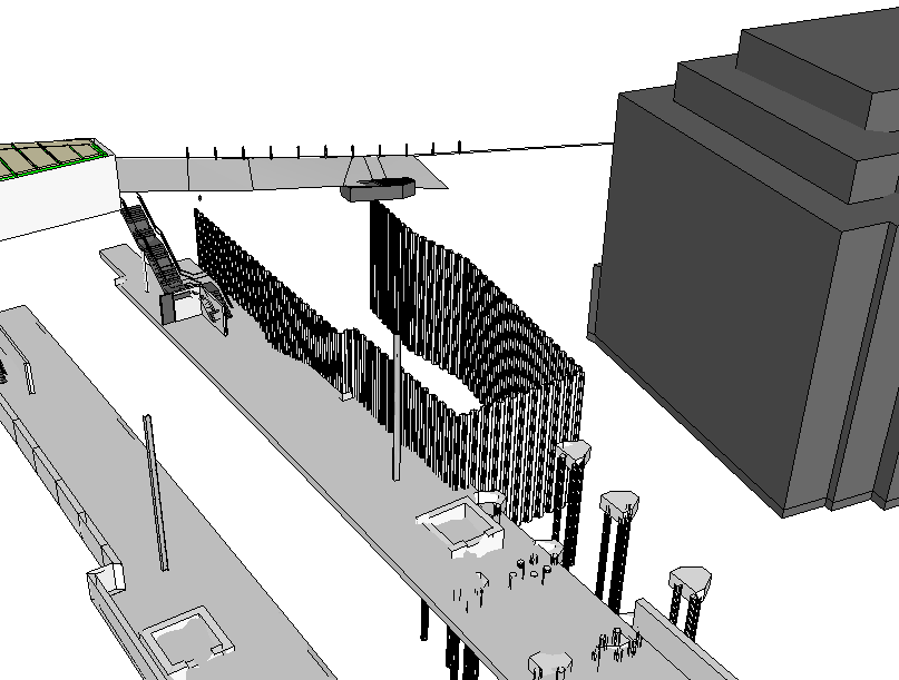
Another day another project. I have started to become increasingly involved in ‘Building 2001’ in Harrisburg, which is the home of the enormous Eastern Distribution Centre (EDC). I say increasingly involved, though yesterday I narrowly avoided arrest, more about that later. The building is pretty large, mainly dominated by a warehouse but with an admin section about twice the size of Denison strapped to the side. The current contract is to replace the roof, change some lighting, improve the ventilation and replace, more or less like for like the HVAC system. And so far the most important lesson I have learned is: Avoid dealing with refits wherever possible! I will expand.
To follow on from Guz’s theme of invention and Rich’s point on people actually leaving their desks to look at stuff. Two things this week have lead me to believe that the designers didn’t actually bother coming to do a detailed survey of this huge building before cracking on with their designs and just assumed the as built drawings were complete and correct.
The building has three plant rooms. The main plant room has the steam distribution and the main elements of the chilled water distribution. The other two smaller plant rooms each service their respective admin floors with an Air Handling Unit (AHU) and some minor switchgear. As it begins to get warm here we are starting to cobble together a temporary system whilst we wait to get the main cooling system on line. So as we were talking through the system in a meeting, so at least better than a chance conversation, the contractor stated that the plant room housing the ground floor AHU was getting really hot; suboptimal in cooling season. We asked why and he said it was obviously because of the two condensers that were stationed in there from some retrofit air conditioning systems.
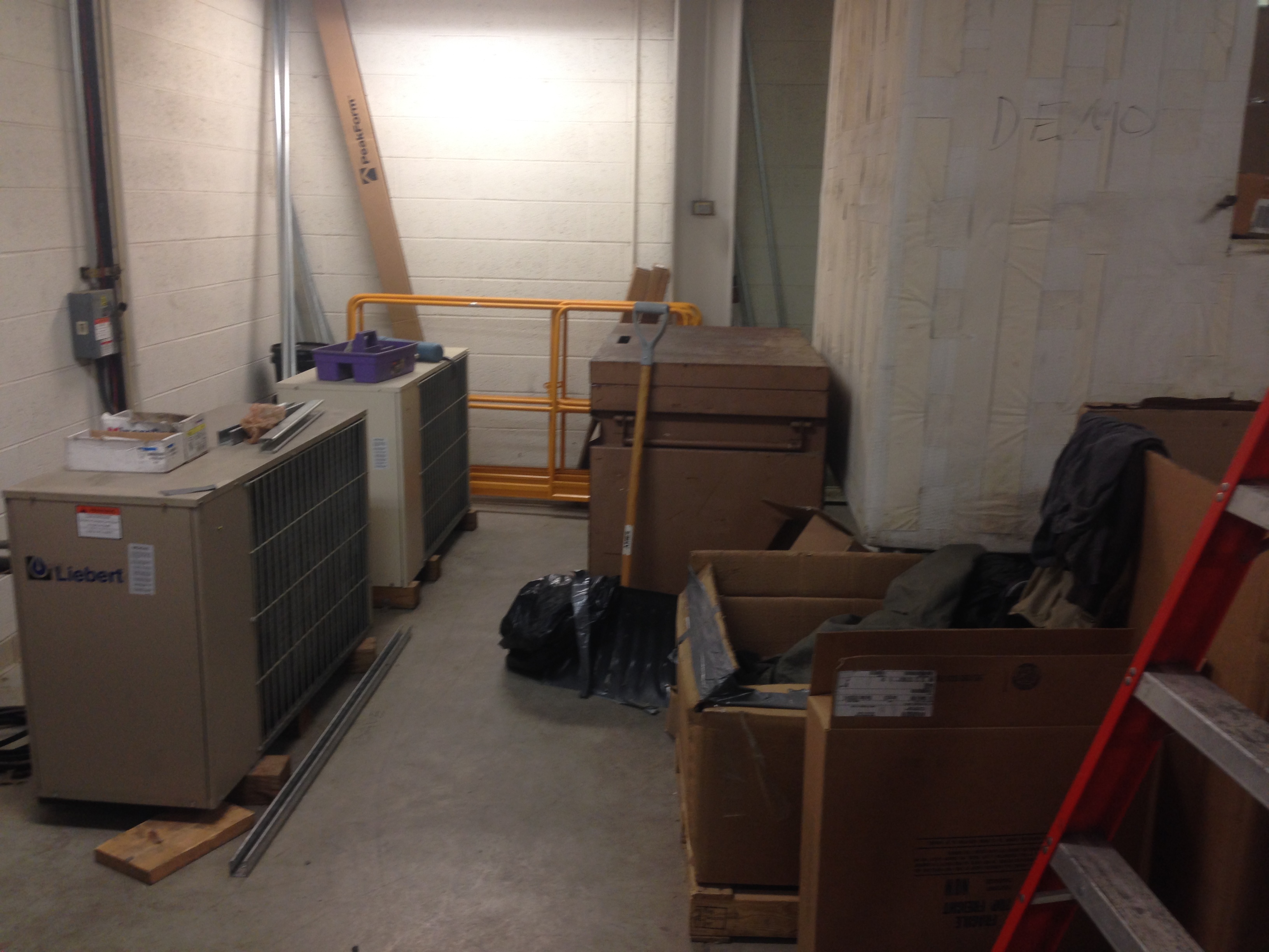
Just heating the room that is trying to cool the rest of the floor. Outside is a mere 20′ away.
Some pipe hunting later and we found that these fed two computing classrooms that had obviously required extra cooling at some point in the last 10 years. Checking the contract these aren’t to be replaced. Now I haven’t checked the as built drawings, but I don’t need to because the photo above clearly shows exactly where these condensers are. So my question is, which idiot put them there and which idiot decided to leave them there in a comprehensive refit of the building’s mechanical equipment. My conclusions are that it comes down either to incompetence or money. But, based on the next example, it is difficult to say it was just a cost saving measure as incorporating a couple of extra outlets into a room to increase the cooling capacity would have been pretty cheap in the grand scheme of things: I think the designer didn’t know they were there.
So to observation two. The biggest reason the air conditioning system is not running is that the cooling towers (condensers) on the roof aren’t connected. This is because someone forgot to design the structural steel to hang the pipes from. So due to the rising mercury we have hired a trailer mounted condenser, complete with pumps. So the question is merely what size?
After a chat between the contractor, mechanical engineer and myself we decided on 500 tons, ordered it and it arrived. When it turned up we proudly went out to observe our $40,000 a month lease and the installation electrical engineer asked when the other one was coming? And that was when email tennis started.
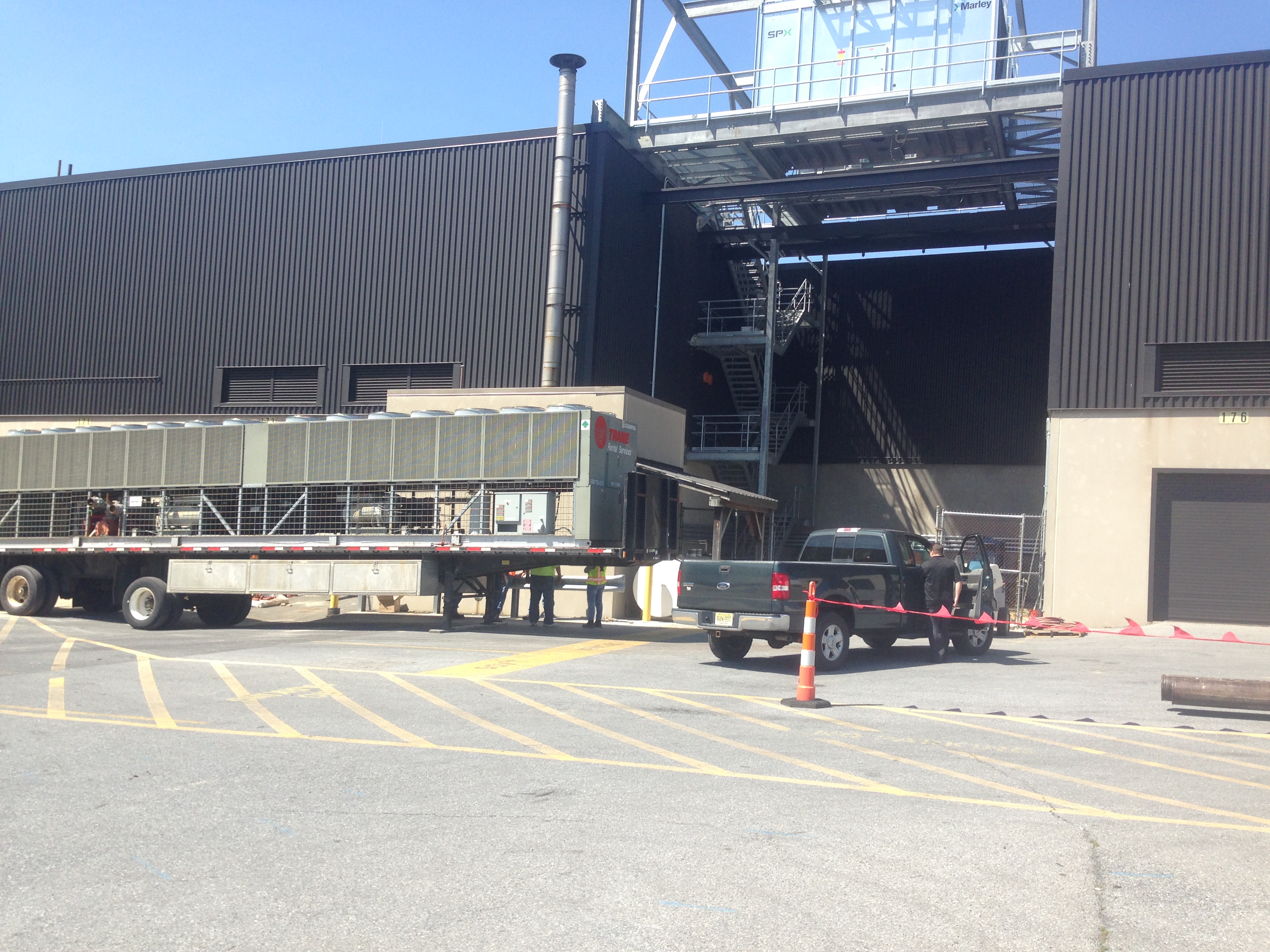
The 500 ton temporary system in the foreground. The new chillers (1300 tons) up high.
The original system was designed at 1800 tons (2 x 900 ton cooling towers) and in the design guide produced by the design consultant there was a magical figure of 1220 tons as the load. The new system is designed at 1300 tons and so the installation decided 1000 tons was the minimum possible. The installation engineers therefore stated that our temporary chiller would simply not be large enough and kicked up a stink with explanations of the old system working flat out and hardly being able to keep pace.
So the proof will clearly be on Tuesday when the system is turned on and the temperature is set to be in the high 80’s for the week. However, I will justify our decision now. The contractor has worked on this building for the last 2 summers and swears that there has only been one cooling tower operating at a time; indeed last year one of them was out of service. He also said that when he removed the old cooling towers he’d called the manufacturer with the serial number and asked the size: 600 tons (for some reason it wasn’t on the nameplate). Additional factors are a number of smaller AHUs have been removed and the temporary power supply wouldn’t run a 750 ton unit. When designing the controls, before my time, we had been told the permanent 1300 ton system was to give redundancy, as out here everything has redundancy.
Conclusions
Having read the design handbook for this project nowhere was there actually a calculation of the load, just an assumption with no justification. Remembering back to the design projects writing why an assumption was made seemed frustrating as it got in the way of moving onto the next calculation. However, the reasoning behind these assumptions are vital in the real world for someone to understand your calculations so they can make decisions later down the line; especially if the situation changes. This applies to references too as a reader can understand your thinking better if they can trace it back to source. It the light of contradictory evidence empirical evidence should take precedence.
As built drawings are not 100% reliable. They may be but it depends on whether someone has the time or funding to keep them up to date. In the EDC there are a number of different organisations with little pots of money doing self help projects all the time so some might not even know where to get hold of the master set of drawings; if there even is one. Thinking forward to doing DfID style projects the odds of getting BIM are pretty long! Therefore time spent on recce…
Oh and my near arrest. Well despite having been working in this building for three weeks it appears I don’t have clearance. Yesterday I tried going in through the main entrance and was told my name wasn’t on the list by the DLA Police. The building is about as secure from entrance as a sieve is from water and holds nothing remotely of interest to a thief or spy but rules is rules. It turns out I just need to present a letter that I am not allowed to see the contents of to the head of security and it should be fine! I can only imagine the pain Brad has been through and I’m pretty glad that the engineer I work with is the base commander’s wife as that probably prevented bracelets.
Making it up
This week’s blog is about stuff that doesn’t fit…
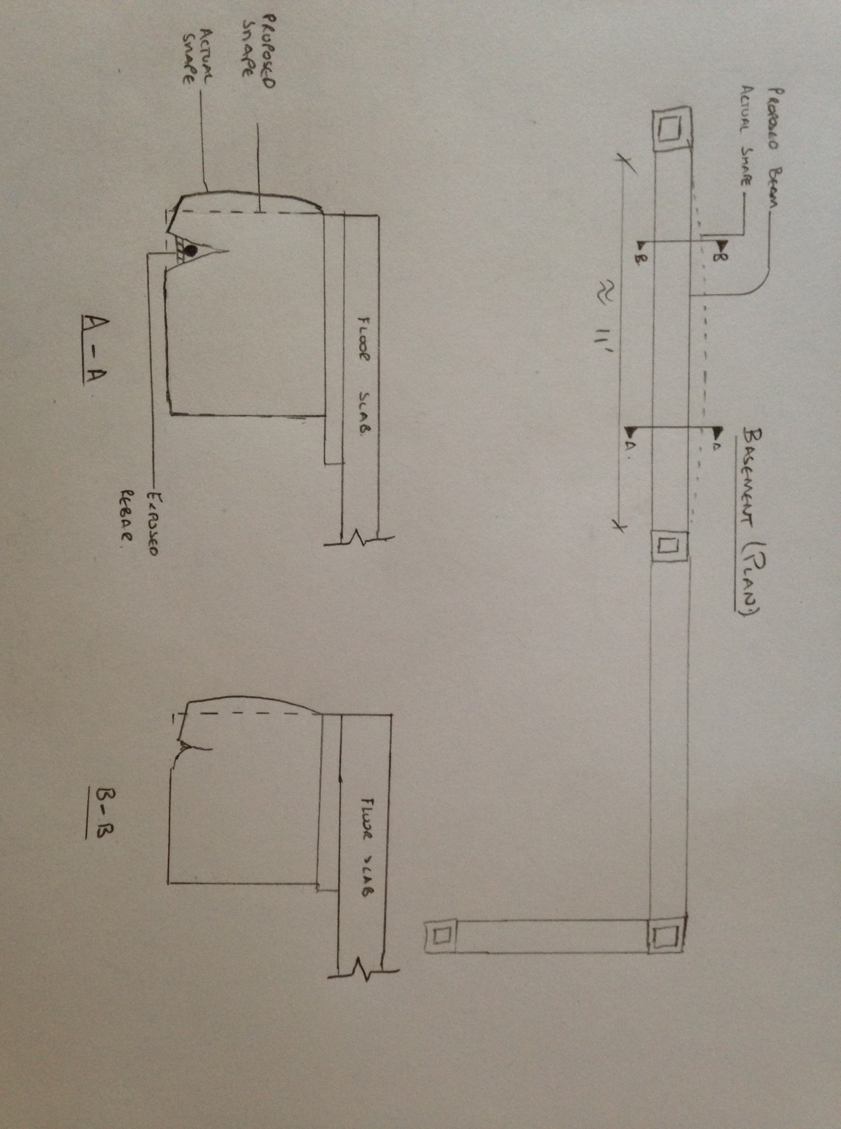
We’ve got a channel for an ACO drain in the steel, and a pipe for the ACO drain, but the two don’t line up. I checked the setting out for the pipe, it was in the correct location according to the setting out information from Arup. I then checked the channel in the steel. It too was in the correct location according to the setting out information from Arup. It turns out that if you overlay the structural drawing and the drainage drawing they don’t line up:
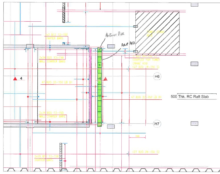
Pink shows structural design location for ACO drain, Green shows the drainage design location
We’ve solved the problem with the imaginative use of a 90 degree bend (which are actually 87.5 degrees, but that’s another story) and a T junction.

I would dearly love this to be the only such balls up, but it’s not. We had a drainage run that should be a straight pipe with a y to a second drain. It couldn’t go there as it would clash with the discharge pipe for another sump. So we tried it the other way round and that clashed with a pile head. So we’ve had to bend it round the pile in order to get it in.
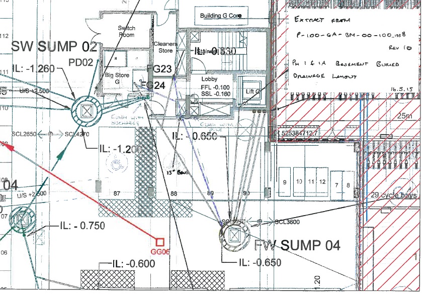

Both the drainage design and the structural design are both done by Arup, so yet more examples of an organisation sending out contradictory information.
But unlike previous examples where it was because people in open plan offices sit next to each other and yet still prefer to send emails rather than have any form of human contact, this would appear to be mostly due to one man thinking his area of responsibility is more important than anyone else’s and assumed that everyone would make their designs fit his. The structural engineers assumed they were the most important and so didn’t bother to check.
We’ve solved all of these problems but it does begin to raise concerns about the competency of the people who design these things. Neil often asks about how on earth they designed something as complicated as the Shard. I fear the answer may be: “They just made it up!”
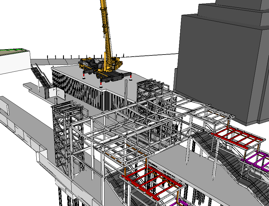
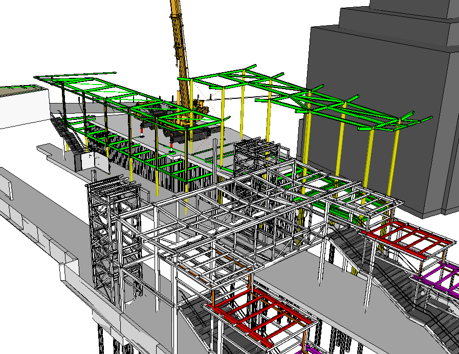
It’s not all bad news though. Our 5th tower crane is up and the site is really moving now. PCH are here only in name but the blokes are very much here in person so we’re progressing nicely!

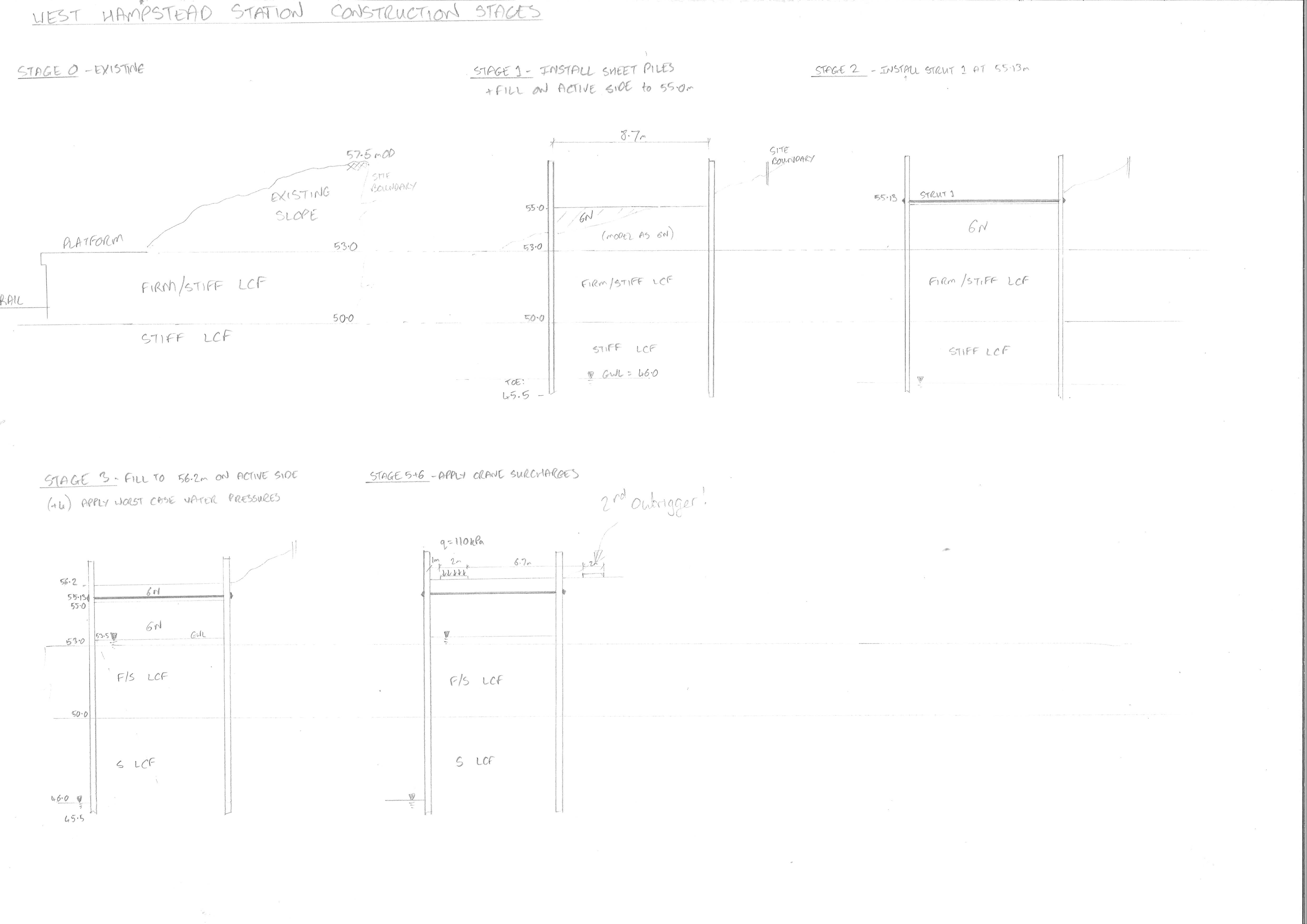
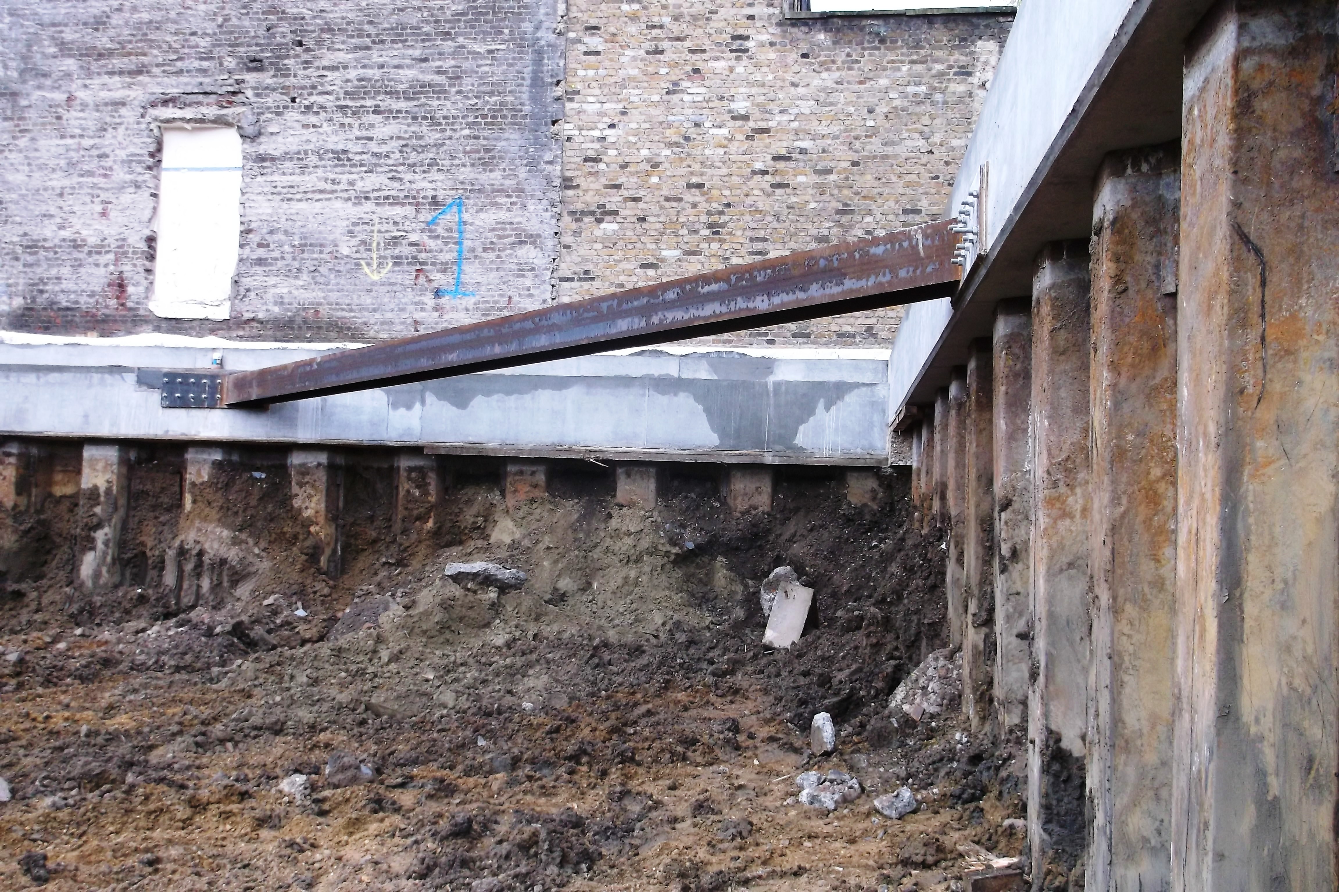
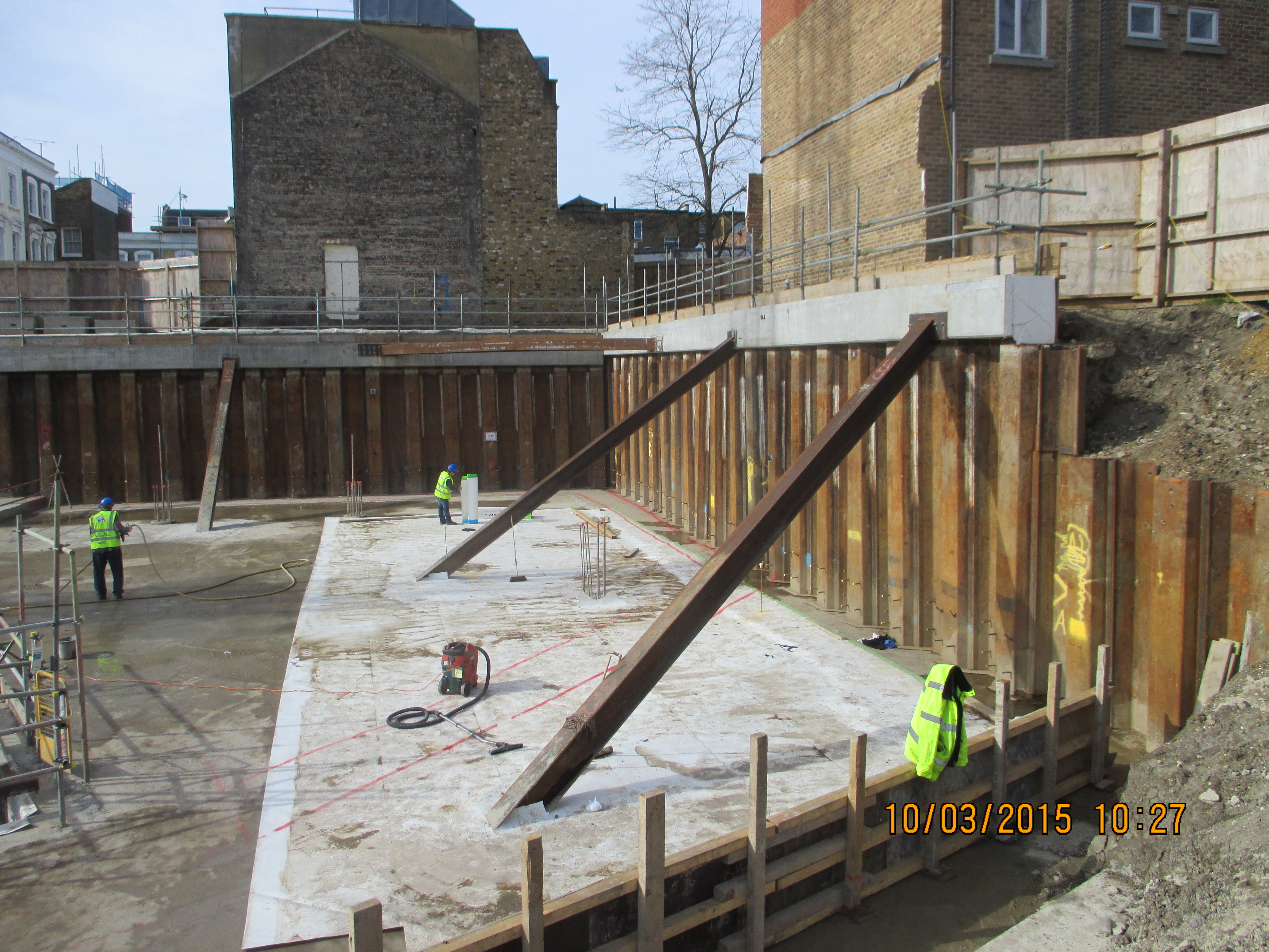
My Passive is Active and piles might get pre-bored!!!
So yesterday I ended up chatting to Richard and John for a while with a question about how pre-boring affects the resistance of sheet piles in clay and how to model it in WALLAP. As I suspected the answer wasn’t a simple one!
The retaining wall is part of the station redevelopment at West Hampsteadand were are designing a cofferdam that will act as the base of a new station building. It will also need to accomodate a large crane during the building of a new footbridge.
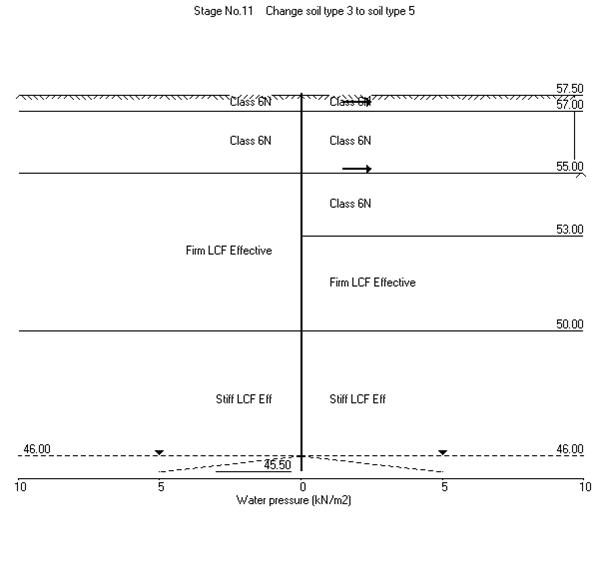
The ground consists of firm to stiff London Clay overlying stiff London Clay and we will use 6N (Granular Fill) inside the cofferdam. I used WALLAP to model the wall nearest the track to obtain the moments and shear forces and strut forces to enable us to design the ties between the the walls of the cofferdam.
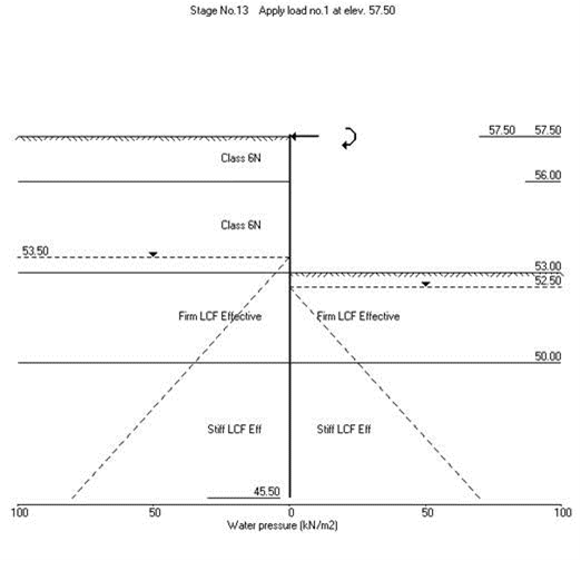
Because the clay is stiff, it may need to be pre-augered to loosen the ground prior to piling. This has an effect on the stiffness of the surrounding soil and vertical resistance. The question was-by how much? After a long conversation with John I established that seeing as stiffness is unreliable squared then your guess was a good as mine! The solution was to do a sensitivity analysis by adjusting the stiffness parameters in WALLAP and see how much it actually mattered. The result wasn’t too significant so we have stuck to values of half of the undrained shear strength and half the stiffness values. We’ve also suggested water-jetting instead-has anyone had any experience of it on site??
Active and/or Passive??
The next part of the problem was modelling the far wall of the cofferdam. In theory because is was in level ground it is acting as a deadman anchor to the main wall using the ties. The ties forces were modelled as horizontal loads on the passive side.
Life would be straightforwards if that was simply the case but because that side also the active side of the main wall we have a problem where the two wedges interact. Since this is quite a common problem I thought there would be lots of literature on it but I was wrong! The BS CoP for Earth Retaining Structures simply says move your deadman further away outside of the active zone:
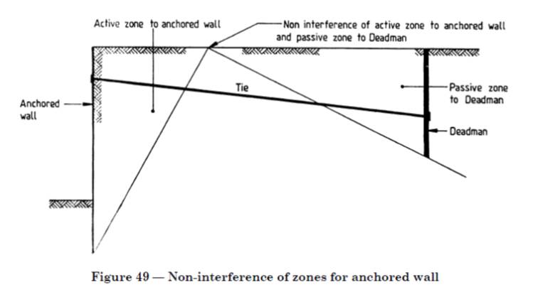
But we can’t do that as our second wall can’t be moved further out and it will become the piles for the building. So we have ended up just adjusting the rigid boundaries in WALLAP to reduce the amount of passive resistance available. It is a bit concerning that there isn’t much written about this when you think about the number of walls behind walls that are holding up various structures everywhere!
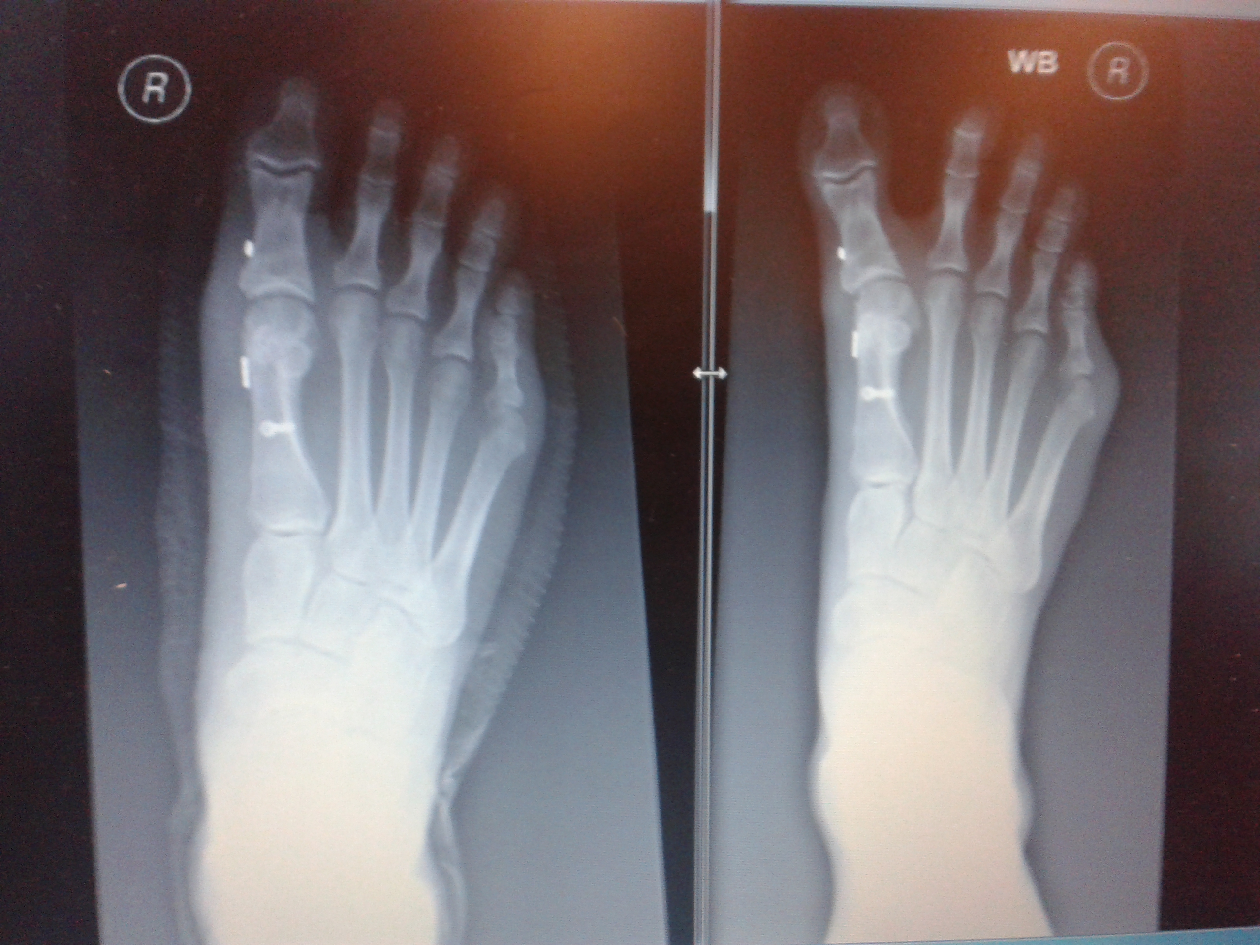
Unfortunatley it looks like my foot doctor didn’t do his maths on the forces that my foot goes through as my podiatrist sent me back to him for a review as my big toe looks a bit wonky again. You don’t need to be a doctor of engineer to realise that the piece of wire between the two metal buttons that goes between my big toe and the next has either snapped or cheese wired through the ligament holding it in place. The Xray on the left was post surgery in Jan and the right was last month. It looks like it will be 3rd time lucky with surgery on this foot and next time he will use wire meant for holding together shoulders and I get a month in my air cast boot 😦
Some additional info to add:
Well I think I had already done what John has said by drawing up this sketch of the Active wedge of the front wall (orange) and what is left available to become the passive wedge (pink) since we have a deep anchor we will have more passive resistance as shown by the pink dashed line too. I had a play around with WALLAP by moving the passive rigid boundary and it didn’t affect things too much. I will also have a go at making the ground slope on the passive side to see what that does.

In response to Howards points here is a section view to help explain the bigger picture. The rear wall will become the piles for the back of the building and the site boundary is just behind it so we are restricted on anchor systems. Our worst case loading is the crane in the temporary condition so once the slab is in place and it becomes a building it ends up retaining less as currently the slab is suspended.
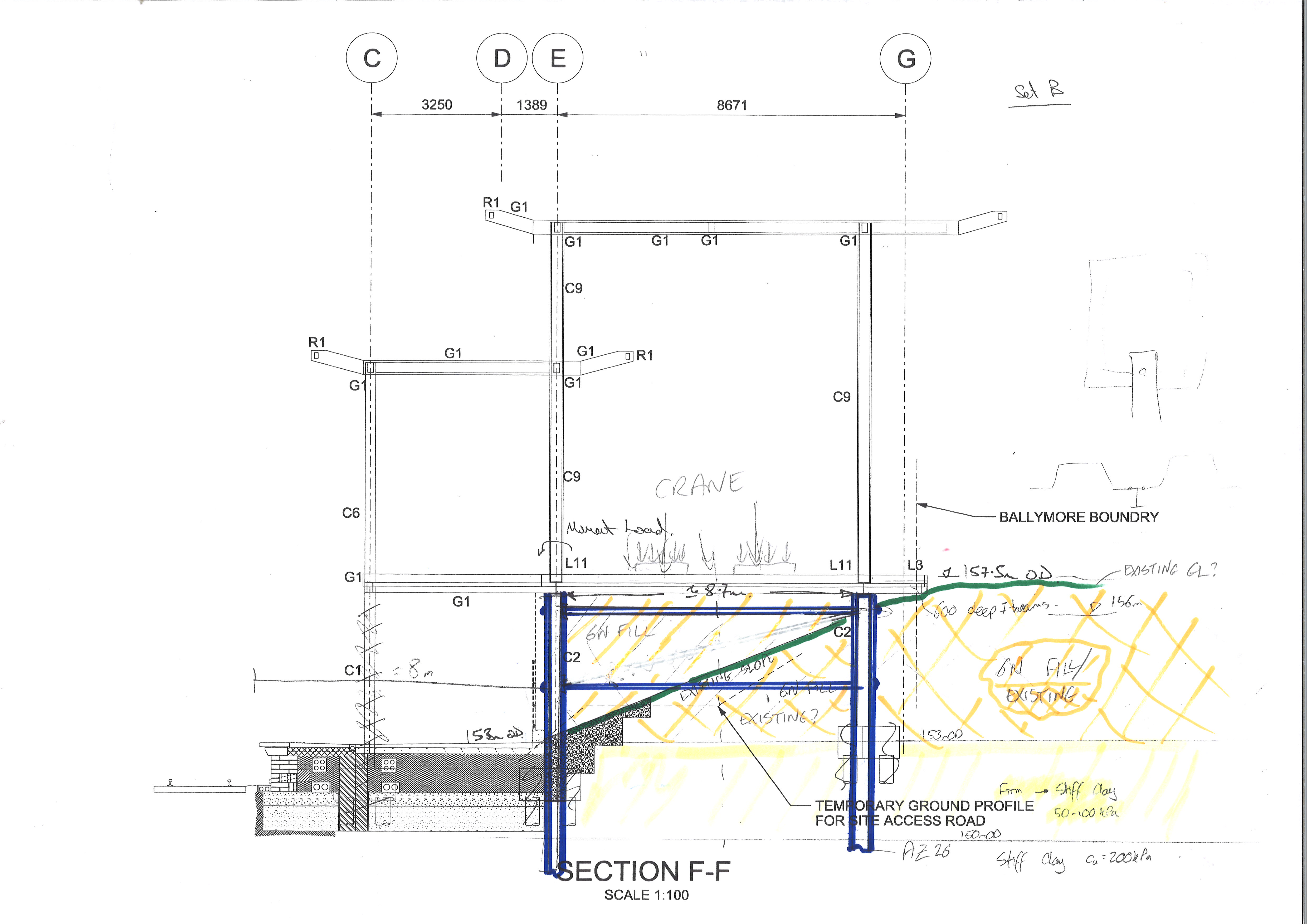
The railway team then decided to throw a spanner in the works and they now want an attenuation tank for surface water just below the slab so we have had to lower the crane and set up a new model. On drawing out the construction sequence I have found a much bigger spanner to lob around as I’ve noticed that their crane doesn’t fit!! I’ve just sent the email that no-one wants on a Fri afternoon saying that not even a crane 1/5 the size of what they need will fit in our cofferdam and they might struggle with the site boundary too!!
Temporary HV
Last week I was surprisingly involved in the installation of temporary electrics. I say surprisingly, because at the start of the week I didn’t think I’d have any involvement in this area of the project. Before I go on any further I’ll explain what the current temporary electrics plan is and how it was / is planned to develop.
The temporary electrics subcontractor is Wyse power. There are currently two temporary substations (TSS) set up in a radial to provide power to the site, with a third that and has now been delivered to site and is due to be energised shortly in order to allow a ring main to be established. The HV power comes onto site through an intake substation just off phase 1 and runs under the road on the western boundary before coming into the basement at TSS 1. From here TSS1 is connected to TSS2 via an internal cable. Another cable was pulled at the weekend which will eventually be connected to TSS 3. TSS3 will subsequently be connected to TSS2 via an internal cable allowing the ringmain to be completed. (Please refer to single line diagram).

Single line diagram showing the temporary HV set up.
This blog will deal with the delivery to site of TSS3 and the pulling of the cable that will eventually be connected to the ISS and TSS3.
My involvement in the delivery of TSS3 and the pulling of the cable came about because someone was on holiday and I was apparently best placed / willing to get involved. This is despite being only aware of what was happening and not read into the detail.
The delivery of TSS3
The delivery of TSS3 should have occurred last Wednesday. The plan was simple, use a tower crane to pick the TSS up from the delivery vehicle and drop it directly into its final resting place.
Problem 1? The substation didn’t arrive on Wednesday and the concrete subcontractors were due to be placing falsework in the area where the substation needed to go. Once the falsework was in position there would be no opportunity to directly drop TSS3 in with the crane as the falsework was for a slab pour. Unfortunately for me the Carillion construction team had been told in no uncertain terms that any delay to the concrete contractor was not acceptable. This led to the area I needed the TSS to go being filled with false work and covered over in preparation for a pour.
Solution 1: Placing the TSS as close as possible to where we wanted it to end up and then sliding it into position once the pour had been completed and the falsework had been removed (the TSS isn’t due to be energised for another few weeks, so curing time wouldn’t be a problem).
Problem 2: Wyse power were telling me that the TSS was going to be approximately 2.5 x 2.5m and weight in at around 5 tonnes. This meant that there wasn’t physically a route to get the TSS into its final position from the available intermediate positions.
Solution 2: When pulling the HV cable that would link up to TSS3, pull as much cable as possible into the basement in order to maximise the chance of being able to reach the TSS without having to pay for a cable joiner to come out.
Final solution: In the end the TSS arrived on site and measured only 1.8 x 1.6m and only 3 tonnes. Therefore, more by luck than judgement, we were able to place the TSS into a position that would allow it to slide into its final position at a later date.
Cable pull:
At the weekend that has just gone the cable that will eventually connect the ISS to TSS3 was pulled. This required the power to site to be switched off due the cable being pulled being in a duct parallel to the existing temporary HV power. Getting the HV power turned off is a relatively big deal involving having APs on site as well as the DNO – everything needs to run smoothly! The weekend prior to the cable being pulled preparatory works were conducted (cable pulling pits established) in order to allow the cable pull to proceed smoothly. The back brief everyone in Carillion had received was that these preparatory works had gone smoothly and that we were ready for the cable pull. However a quick chat between the groundworks supervisor and myself highlighted that everything wasn’t quite so squared away. In order to get the cable into the basement there needed to be a hole in the kingpost and sheet pile walls for the cable to pass through – there wasn’t. Fortunately this conversation happened at the start of the week, so it was fairly simple task to get the sheet pile wall cut down (the capping beam has yet to be put in position and will be formed around the cable duct), and a hole cut in the king post wall.
Comments / reflection:
My involvement in the temporary electrics came about because someone was on holiday. In future I need to do a bit more of an estimate as to what might come my way when people are away so that I can better prepare myself.
Everyone knew when TSS3 was supposed to be being delivered, but nobody had highlighted the critical nature of the delivery window – communication is key. A 5 minute conversation between the MEP team and the package manager for this part of the building would have highlighted that the falsework was going in imminently and could have led to the delivery date being brought forward to allow for unforeseen delays, or additional pressure being placed on Wyse power to ensure the delivery date was met.
Wyse power didn’t know the specs of their own transformer – everyone is a middleman. This detail should have been known in advance. In addition I should have questioned Wyse Power’s dimensions more. I could have looked at the dimensions of similar MVa transformers as a reality check on what Wyse Power were telling which would have simplified the issue of getting the transformer in position.
The groundworks contractor knew that the HV cable had to run into the building and that there weren’t any penetrations in the basement wall. Why didn’t they report this first thing on Monday morning? Why did it take a chance conversation to highlight the problem? Talking to people when you’re walking about on site it key to finding out and confirming what is actually going on. Also don’t take what you’re told at face value, question it and check for yourself.
Site Two Fifty One – Environmental Awareness
As site Two Fifty One continues to get established part of the works have included moving the hoarding outwards. This gives more space inside and sets the correct position for the entrance gates. However, outside of the original hoarding line were 6 mature trees (trunk greater than 100mm/greater than 10 years old). They now sit within the site.
Left – See concrete blocks with posts on – this is the original hoarding line. Right of tree – see blocks moved to edge of pavement, tree will now sit “inside” the site.

Tree within hoarding creates ecological value, therefore making it harder to gain credits for improving the site’s ecological value in the future.
So What?
The original site survey in 2007 determined that no trees sat within the site, therefore it was classed as having a ‘low ecological value’. This presents two advantages: 1. No effort required in protecting trees or other species and 2. Using the Building Research Establishment Environmental Assessment Method (BREEAM – See areas below) and Code for Sustainable Homes it is easy to gain credits by planting trees in the future to turn the site into a development with ecological value.
- LE 02 – Ecological value of site and protection of ecological features – Two Fifty One is starting at a low baseline (i.e. no trees within the site).
- LE 04 – Enhancing Site Ecology (easier if LE 02 is met because low start point)
- LE 05 – Long Term impact upon Biodiversity (add more trees!)
This reminds me of John’s brief of Rich Phillips’ TMR discussing BREEAM based credits gained for little extra effort (points for being near a bus stop – quite likely in a high population urban development!). The aim is to avoid the loss of credits, which in all tally to give a ‘very good’ rating, would mean the project would slip down a notch and therefore not comply with planning consent. Seeing as the client is still to approve Laing O’Rourke’s tender for the superstructure, now failing to meet the planning requirements would be pretty embarrassing.
So how is this problem going to be resolved. Along one side of site it is simple; sections of hoarding will be moved to inside of the 5 trees. Unfortunately, one tree in a different part of site cannot be easily excluded from the site. BS 5837:2012 (Trees in relation to design, demolition and construction – Recommendations) states: “It might be feasible on some sites to use temporary site office buildings as components of the tree protection barriers, provided these can be installed and removed without damaging the retained trees or their rooting environment”. This is particularly handy because the site store is going to be positioned next to this tree and will actually act as a useful barrier to prevent damage to the tree. This means the tree is protected
Is it right that credits are given for a tree to be outside or inside a hoarding line? The advantage is, if it is outside, the trunk will not be knocked and bashed by construction traffic or have materials stacked against it. It also means that the development is likely to have a focus on green areas and planting vegetation – which is a good thing.
So in all, is BREEAM and the Code for Sustainable Homes actually going to help the ecology of the local area? Somewhat. By signing up to the “Very Good” BREEAM rating the project is accountable for carrying out its actions as it said it would to the local council. Therefore simply removing trees cannot happen and even small things like protecting trees will be taken seriously.
Oz PCH – Smokey and the Bandit
This week, amongst other tasks, I have started on one of my main project responsibilities; that of managing the Cause & Effect (C&E) Matrix. The C&E Matrix details all the outcomes required of certain building services systems in the event of a fire, like; smoke management; lift function and door access control. The fires suppression and alarm systems being managed separately. The obvious priority in a fire situation is preservation of life but in a hospital you can’t start wheeling hundreds of beds down corridors in order to save little johnnies’ life and there will be a number of patients in various states of critical conditions where they are hooked up to all manner of support systems, so staged zonal evacuation is required and extinguishing the fire becomes a very close second priority. However, the biggest killer in a fire situation is smoke inhalation.
Cause & Effect Smoke Management
Who’s who?
Advanced Solutions (AS) – Smoke Management Services.
Schneider – Technology Interface.
NDY – Design Consultancy Sub-contracted to JHG.
The System
I attended my first C&E mtg, this one regarding just the smoke management in a fire situation and to be honest I didn’t really fully understanding the systems in place and found a lot of the detail going straight over my head. However, post mtg and with a little explanation from my LM it started to become clear.
In the event of a fire the smoke created as a result provides the easiest means of detection, especially when you consider a fire could break-out in any room throughout the vast number found in a hospital and potentially in a non-occupied one with no-one present to see the flames and hit the alarm. Smoke, being a by-product of the fire is hotter than the surrounding air and so rises thus making it easier to detect from high level (usually ceiling) mounted detectors. I’m not going to discuss the methods used for confirming the fire, extinguishing it and the alarm systems here so will leave that for subsequent blogs. What I am going to cover is how the smoke management system was designed to work and its operation.
The building is provided with a zone smoke control system throughout. The zone smoke control system utilises the return air system of the air-conditioning as smoke spill (detection). In support of the building’s zonal smoke control strategy, all of the significant AHUs within the building will be used to control and limit smoke migration. When smoke is detected in a fire-affected zone it uses an extraction system to remove it from that zone and simultaneously shuts down the air supply (via the AHUs) to create negative (-ve) pressure imbalance in that zone. Supplementary to this, air supply fans in adjacent zones ramp up and the extraction fans close thus creating positive (+ve) pressurisation in order to ensure inward migration of clean, smoke-free air into the fire-affected zone which assists in keeping the egress paths relatively clear of smoke.
All fire management systems should be powered from the Essential Supply (ES) because the ES is backed-up by the stand-by generators (UPS) so in a fire situation the ES is more likely to remain functional over the Non-Essential Supply (Non-ES) which isn’t backed-up. The two systems then operate; the extraction sys by controlling fans to extract smoke out of the building; and the pressurisation sys by controlling the Air Handling Units (AHUs) and various dampers/fans. The fire zones generally coincide with the AHU zones and it is these that determine the various AHU behaviours in the event of a fire, although some adjacent zones may not contribute towards zone pressurisation e.g. adjacent zones crossing the atrium from East to West Towers – see below examples of AHU zonal layout of the ground level and level 2.
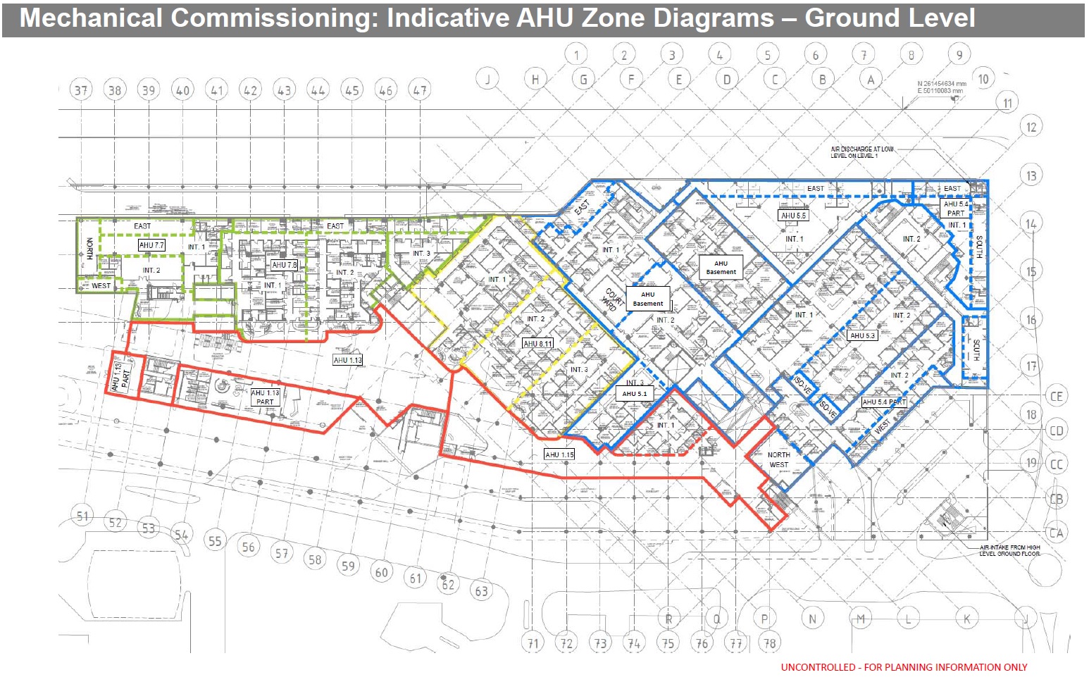
Ground Level AHU layout by zones.
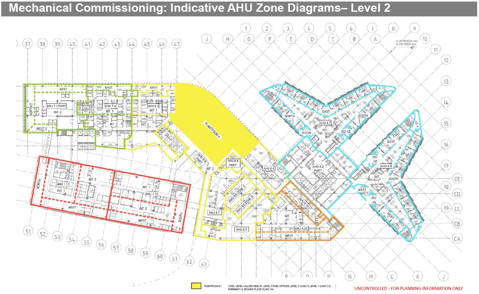
Level 2 AHU Zones – You can see pressurising West Block zone (red) will not positively affect the East Block zone (green) as the atrium in the middle will prohibit effectiveness.
The Issue
In order to control the zones both extraction and positive pressurization are used to create a pressure differential of not less than 20Pa (20N/m2) but not more than 100Pa (100N/ m2) between any single fire-affected zone and its adjacent non-fire-affected zones in accordance with the requirements of AS/NZS1668.1:1998 (Australia and New Zealand’s Standard for the use of ventilation and air-conditioning in buildings – Fire and smoke control in multi-compartment buildings). 20Pa is actually quite a lot of differential across a doorway and would require quite a high air flow rate to achieve this. The maximum being 100Pa is due to the required force to open a door is not permitted to exceed 110N. It is generally accepted that for most applications a positive pressure of around 20Pa in non-fire-affected compartments with respect to the fire-affected compartment will minimize the spread of smoke. A higher pressure should be designed for where ceiling heights exceed 3m; 40Pa is suggested for 6m high ceilings. Using both systems allow the greatest amount of flexibility when concerning complex zonal layouts where certain rooms (dependant on their designed use) are a higher priority than others to remain smoke free (see rough sketch below). However, it is possible to create the required pressure differential from extraction alone but it offers less flexibility and may even be impossible in certain scenarios (see basic differences between systems in the second pic below).
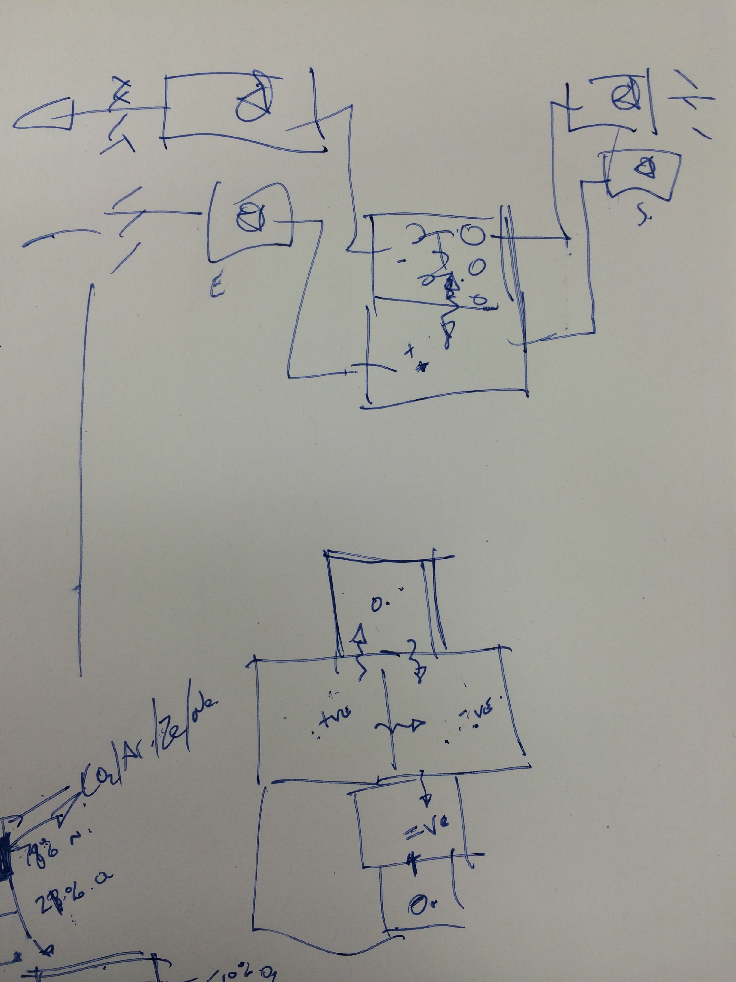
I know this sketch is very ‘Jonny age 5’ but in drawing it, it aided understanding in the potential complexities of adjacent rooms requiring different pressurisation.
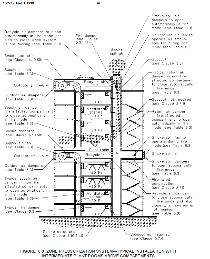
However this diagram (from the AS/NZS1668.1:1998) does explain pictorially how the two systems work together including what each type of damper should do in the event of a fire dependant on if the damper is in the fire-affected zone or not – this is indicative of building layout in the PCH project having plantrooms between levels.
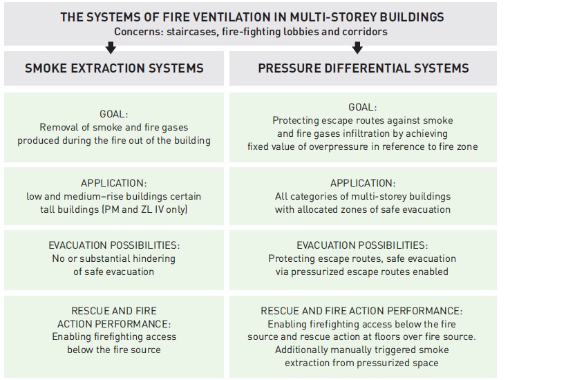
This is an extract from iSAFTEY WAY – Pressure Differential Systems in High-Rise Buildings describing the basic features of smoke extraction and pressure differential systems.
Therefore the design from NDY was to use both extract and positive pressurisation…and here’s comes the but…but approx. 40% (36) of the 91 x AHUs (see pic below) are on the Non-ES which could cause major problems because, as mentioned above, the Non-ES is not backed-up and thus if the fire damages the Non-ES, power to AHUs will be lost and thus not operate as intended.

AHU Layout across all levels and Blocks. Each box (less those that say Commissioning Plant Room) represents one or in some cases more AHUs.
The Solution
Our view is that all AHUs should be on the ES but NDY say they can achieve the required zonal pressurisation from extraction alone so we have asked the question for them to confirm that’s the case. If so then everything should be ok but if not then it’s a gargantuan problem and will cost hundreds of thousands to rectify in changing the power supply to approx. 60 x AHUs; which would consist of changing connection to different MSSBs, cabling etc, etc.
Once the above issue is sorted and the system can theoretically pressurise zonally either by only extract or a combination of the two systems then Advanced Solutions (AS) will ensure their control management is in place for all AHU dampers/fans to operate dependant on the requirement for a particular room/zone and thus manage the smoke.
The Hard Part
The hard part is in the testing of ALL AHUs and dampers/fans reacting as intended along with the other more onerous task of physically checking the other C&E systems work as intended, for example; ensuring that every door within or on the boundary of a fire compartment automatically disengages from its magnetic hold open device to close thus preventing the spread of smoke and fire and that non-fire rated motorised doors or smoke doors located on escape routes are to continue to operate as required until power failure at which point they are sprung loaded and will fail safe to the open position. Also allowing any secured access doors (via swipe card) to release on general fire alarm activation to ensure free egress. Additionally there are protocols for all other systems including; fire shutters and roller shutter doors; lifts; pneumatic tube system (carrying predominantly blood samples); gas supply; Automatic Guided Vehicles (AGVs); and miscellaneous systems, such as medical gas supply. The execution will be very time consuming and imperative that we get the recording of results right as the C&E Matrix forms part of the handover documentation for the Client and indeed the building users.
In Other News
I was shown this in the office and found it quite funny so thought I’d share it with you.
More Bent Stuff
This weeks thrilling instalment follows on (inadvertently) the theme set by Guz and Olly. Apparently.
I have just completed my transition week, which now sees me as a Project Engineer out of an Area Office (a more familiar construct for those who have been / are in the US) working on two projects and also minor obligation back to the PM and PrM Office running the contract I have set up. As will be usual for most I had to undergo a site safety induction, ran by the principle contractor of the site on which I will be spending most time. With reference to mine and Henry’s last comments; the brief was actually fairly impressive and many of the standards that are in place are similar to those I experienced in the UK, with a few exceptions (so far – The rickety ladder of doom, no requirement for banksmen for reversing vehicles, gloves optional unless doing specific tasks)
Site itself is fairly dynamic and its not unusual for it to be almost unrecognisable from one visit to the next, particularly with concrete pours; movement of fill material from one area to the next to facilitate access; creation of new haul roads etc. This will only become more disorienting with the award of, now, two new jobs on what is already a complicated and congested site. An area that I am tracking is the interface between two projects, one of which is responsible for the placement of services and utilities in an area which falls within the new project’s Limit of Disturbance (LOD – AKA a boundary). This is an interesting issue because there was a change order submitted to accelerate the placement of the utilities months ago, however this was cancelled when the schedule for the new work was reviewed and it was seen that no work was going to take place until after the utilities were originally scheduled to be placed anyway. So, a requirement was included in the contract for the two Principle Contractors to de-conflict activities where there were pinch points in LODs. There are now mutterings however that the principle contractor on the new job (who is apparently very savvy when it comes to working with the government) is expected to submit claims to the government due to a change in site conditions, which precludes him from going into an area that he doesn’t intend to go into anyway. Good!
On a more real time issue, myself and another Project Engineer inspected a deficiency yesterday on a basement structural RC beam. It is still propped and not fully load bearing yet however there is a large crack running pretty much the length of the beam (c.3.5m) which varies from around 300mm wide in places to c. 50mm and is deep enough to expose the reinforcement. (For Damo’s amusement I have attached a Sketch)
There is significant bowing to one side of the beam which seems to indicate that the formwork has failed which has allowed concrete to pour onto the floor below and caused the deformation of the beam. The deficiency has been highlighted to the designer for inspection and comment. I expect that there will be a requirement to chip away the majority of the side of the beam where the deficiency is and either replace the concrete around the existing pour as is, or epoxy some steel dowels (form savers or similar) and replace the concrete. There may be some practicality issues with this solution as the beam is obviously supposed to be flush with the floor slab.
Other ‘interesting things’ I have seen:
- Mixing of red dye into concrete surrounding some electrical utilities so that any future workers will be able to identify what they are potentially about to dig through. I thought this was ingenious – is it common practice: have I just completely shown myself up?!
- The way that schedule changes affect the engineering of a job. The basement slab has not yet been poured due to weather delays and a desire to get out of the ground. Therefore the basement walls (essentially now cantilevered) have been extended in order to resist the moment imposed due to the active lateral earth pressure
- The utility of a road traffic sign (presumed stolen) as part of some pretty sketchy looking formwork. It was only a pour below knee level or so, and was not structural.
- An excavator, almost excavating under itself as it sat atop some fill material, which was clearly exhibiting signs of face slippage. I highlighted this to the Engineer I was with (Geotechnical background) but he didn’t seem bothered. Apparently if the Operator were to ‘feel it going’ he would simply put his bucket down to the ground. ‘They’re pretty quick off the mark with those buckets.’ Good to know.
- Slump testing concrete at point of arrival and point of placement. There was a bit of pushback when this was spotted in the specification from the designer, however they would not budge. Personally I can see the utility for pumped pours where some slump is gained after pumping. For one, any sub-standard batches are caught before the pumping begins, for two, any batches that are close to the limit (4”-8” in this case) at delivery can be verified at placement and the requirement to return a batch ‘just to be on the safe side’ is mitigated. This is important where timing is critical, especially on larger pours, when the formation of cold joints in the slab is a potential issue. (seen before on the site)
- Construction sequence affecting design – whereby holes have been left in the first floor slab to allow for stores to be lowered into the basement at a later date when the basement slab is eventually poured. This has meant additional reinforcement requirements at the corners and the placement of form savers to allow rebar to be placed across the void at a later date (screwed in) to allow continuity. Also – similar gap exists adjacent where the tower crane currently sits.
I also attended a webinar event ran by the NCE titled ‘Building the Age of Resilience.’ It pretty much took the form of plugging the following product (which I have never heard of) : www.globalcalculator.org
From what I can gather this tool enables the user to postulate future global scenarios of energy requirements, industrial output, global consumption of meat, fuels and goods etc and simulate the effects on global temperature. This video https://www.youtube.com/watch?v=2_6flonHN0o is a brief tutorial on how to use the tool but it’s fairly self-explanatory. From what I can gather unless you are the CEO of a company trying to assess some strategic direction, or the Prime Minister then it’s really just an interest thing, but it is actually, sadly, quite interesting! I guess if you are trying to assess the future impact of a single project you could potentially (at the concept stage) adjust a single ‘lever’ and see if the economic impact to the project is worth the engineering effort? Perhaps.
Pile Collapse
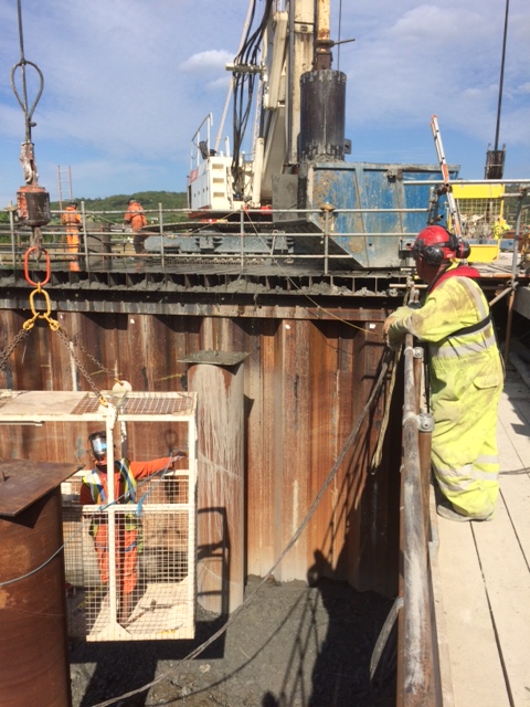
The west abutment piles (8No, 900mm dia, 40m deep) are now complete and passed the working load test with ease. We are now in the process of blinding the area to create a working platform prior to integrity testing the piles tomorrow.
West Abutment Pile Test
The west cofferdam is complete. The excavation turned out to be more complex than we anticipated and caused numerous problems. Eventually we managed to dig to depth and blind without having to fit the intended lower waling. The top of the sheet pile walls have been capped and a UB panel roof has been fitted. The 80tn piling rig now sits on top of this and bores through the open cofferdam and into the ground below. A piling case gate has been fabricated to stabilise the case above ground level and help locate it whilst being lowered.
80tn Rig on Cofferdam. This is the most unusual place the Piling Foreman has piled in 30 years
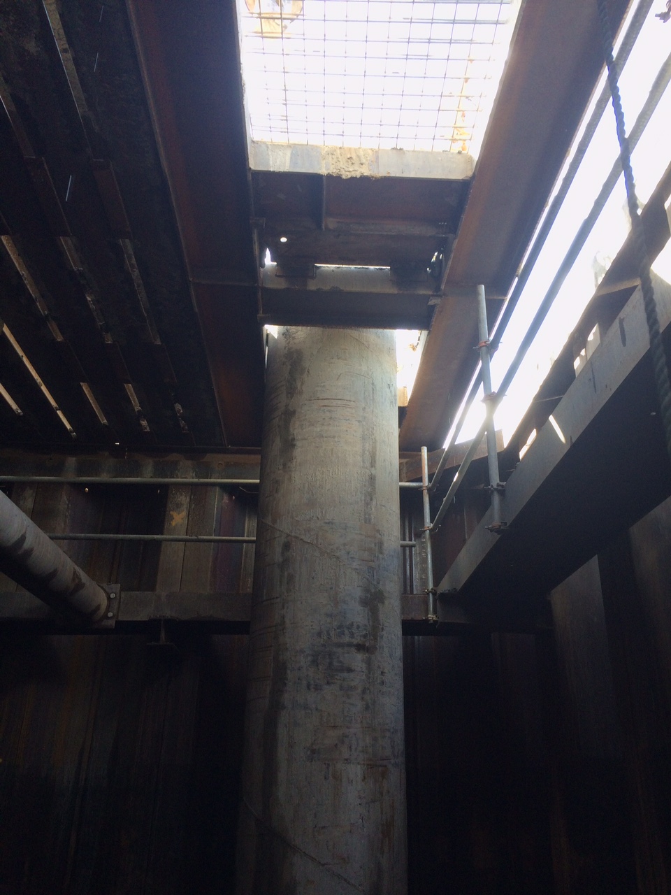
Piling gate and pile casing.
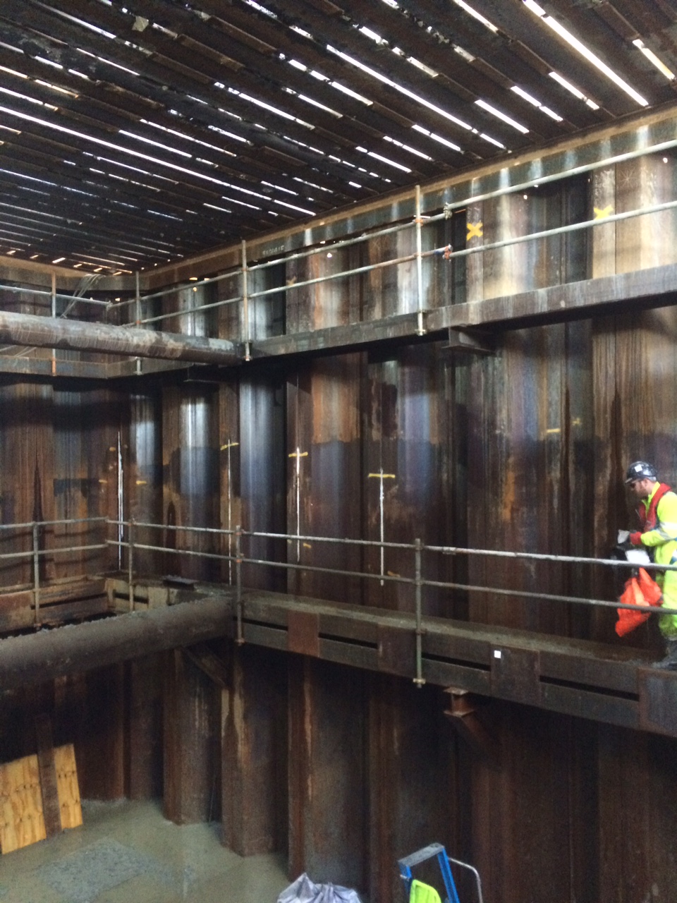
Inside the west dam with the rig above.
The casing starts 1m above the deck and drops 8m through open space and a further 5m into the ground of which 3m is toed into dense clay. The first problem this throws up is that the pilers can’t see the ground level down the shaft, to resolve this issue they have cut a window in the casing above ground level that they can look through from the base of the cofferdam. This window also acts as a water escape when the concrete is being poured allowing us to capture the spill in the dam. It also allows us to monitor the concrete to ensure we are not over filling and creating a large mess (7m3) when the case is pulled.
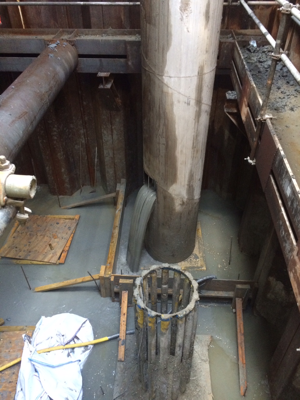
Pile casing with window during a pour. Excess concrete is kept within the simple shutter and cleared up by hand 12 hours after a pour.
Working on top of the cofferdam has caused a few logistical problems, there is no space to store any equipment and the spoil has to be spun off in to a skip and then craned on to the land which slows the whole operation.
Bore spoil is spun in to a tipper skip. Note this is not an accurate process and we lose some over the edge which has to be recovered.
All has been going well and we are completing them at a rate of one a day, until…TODAY!
The piling gang are on a fixed price contract and are clearly keen to get the job done and move on. They asked last week whether they could auger out at the end of a day and then concrete the following morning. This is outside of the 12 hours that is permitted to leave a bore open. On Tuesday approval was granted that this could be done under strict rules:
- 12-24 hrs open – increase the depth and cage length 1m
- 24-36 hrs open – increase the depth and cage length 2m
- 36-48 hrs open – increase the depth and cage length 6m
These rules were issued by the piling designer and based on 10% reduction in shaft resistance per 12 hours. When question on the 10% reduction they simply responded with ‘it’s over designed to negate any risk’. This makes perfect sense, as any decision to leave a bore open would be with the piling contractor and as such any increased cost in materials, time and risk would all sit with him, not us or the designer.
That same day (Tuesday) the rig broke down just after they have reached full depth. By the time the rig was fixed (Wednesday) and it had got back on task, cleaned out the shaft and augured out the extra 1m (rule 1) they had missed the concrete window and had to leave the shaft open again overnight.
When they came in this morning (Thursday) they found that the 43m shaft was now only c.20m. Due to the casing they are unable to see what has collapsed. We are currently pumping 10kN concrete in to a hole with no real idea where it is going or how much of it we will need to cap it off.
So what…
We must now treat that area as unstable and move the piling operation to the other side of the cofferdam and work back towards it. The pile designer has been briefed and will now carry out a redesign of the failed pile. We expect them to either design a number of smaller piles to be placed around the failed one or to insist we re-auger in the same location though the low strength concrete. We are unsure how wide the collapse area is and whether it has affected the existing piles or fresh ground that we are due to pile through in the coming days. Either way the replacement pile/piles will require full casing to depth which will increase the duration of the job.
In other news…
we bent a waling!!!
Sheet pile was stood unslung in 3m of alluvium which has a Cu of about -15!!! When the vibro was lowered on it pushed the pile which sank immediately and dragged the waling with it!
Bent stuff
It’s been a couple of weeks since my last blog thanks to TMR 1 consuming my time and then I was away for a week.
Life on site has been interesting…
Yesterday a man got 5 minutes into the induction before asking for written, signed confirmation that if PC Harrington go under (which they have), Sir Robert McAlpine will pay him. We couldn’t offer that, so he left.
On a slightly more technical note I have spent most of today trying to work out if the sheer pile wall will fall down if I take a corner prop out. The prop is really bent. It was hit by an excavator during the dig. It’s meant to be straight and connected to the capping beam each side by a plate and some fairly serious bolts. Since the beam is as bent as it is, I think that it’s load bearing capacity will have been severely reduced. Which temporary works are designed to withstand impacts, this was a big one. Look at the deflection! Additionally it would appear to have lifted away from the capping beam at each end, so isn’t in proper contact anyway. Also the inclinometers, prisms and google maps so no movement on the sheet pile walls. So I think it isn’t really carrying any load. However I can’t prove it. And without an ability to prove it, no one will take the risk on taking it out.
Beam as installed
Beam post strike
So instead the subcontractor will be required I box around the beam. Wait for the concrete to cure enough and then allow the slab to take the strain before the beam can be removed.
In other news we’ve just changed caterers in the canteen and the lunch menu has significantly improved!