Archive
Oz PCH – Commissioning Jim but not as we know it…
Precommissioning Checks of Water Distribution Commissioning Valves
Who’s who?
Fredon – Mech Infrastructure Subcontractor (work areas includes; plant rooms, services risers and entire basement plant room).
Centigrade – Mech Fit-out Subcontractor (work area includes; floors and corridors).
Why two subcontractors installing the same equipment? Threefold; to reduce the risk attributable to one subcontractor; to reduce the workload to a more manageable % of the overall build; and to ensure one subcontractor wasn’t responsible for too much cost (Fredon’s contract was originally worth approx. AUS$40.7 million but more likely to be AUS$48 million and Centigrade’s originally AUS$27.2 million but more likely AUS$31 million). The important factor is ensuring each clearly understands their working boundaries.
The Issue
In order to commence testing and commissioning of the hot and cold water system, precommissioning checks state that commissioning valves need to be fixed in place in order to measure and balance the flow rates and thus prove the system. On inspection of a number of commissioning valves in a number of plant rooms it was found that they had been installed incorrectly – in some cases there wasn’t sufficient straight line pipe before or after the valve which would skew any readings taken. CIBSE commissioning code and NDY specifications stipulate the valve must be installed at min straight length of 10 x dia upstream and 5 x dia downstream of the valve (as below).

CIBSE Commissioning Code Standard.
However, checking the valve manufacturer, Tour & Andersson’s (TA), data sheet it stipulates the valve must be installed at min straight length of 5 x dia upstream (10 x dia if connected straight to a pump) and 2 x dia downstream of the valve, as shown below.
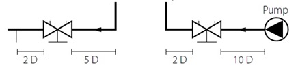
TA Commissioning Standard.
The manufacturer’s data sheets were checked in order to back up our argument (more on that later). Firstly you’ll notice a difference in the downstream length between what CIBSE (5x) and TA (2x) stipulate but you could argue that as the point at which the length is measured from is different, that actually the manufacturer (TA) is approx. 5 x dia when you add the length of the valve itself (approx. 3 x dia). Therefore, only the upstream lengths are different but TA does say 10 x dia if the flow is coming from a pump (essentially creating more turbulence than a bend or change in dia so requiring more length in which to settle back to a more laminar flow) and so worst case is to use 10 x dia upstream and 5 x dia downstream – which is what JHG and NDY stipulate.
In addition not only were the straight line distances incorrect but worse still the pipe line dia was different to the valve dia. In one case there was a 12.5mm dia pipe with a 20mm dia valve fitted in the middle. Below are examples of what was found.
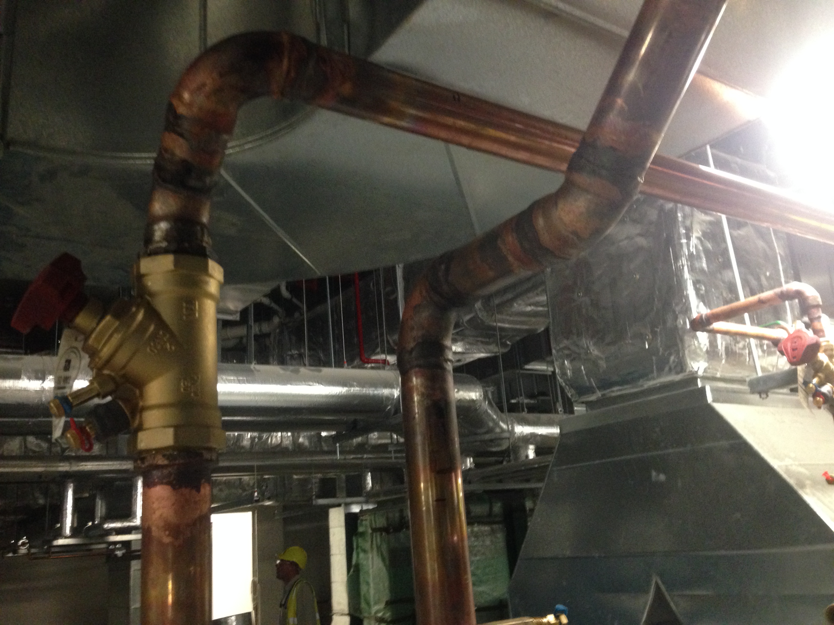
Plant Room 6 Level 4 – flow is south to north. The upstream (south) is within limits (10 x dia) but the downstream (north) should have a straight line pipe section of at least 5 x dia. The valve is 50mm dia = 250mm. Clearly the angle change and then the 90 deg elbow are both inside 250mm so out of limits.
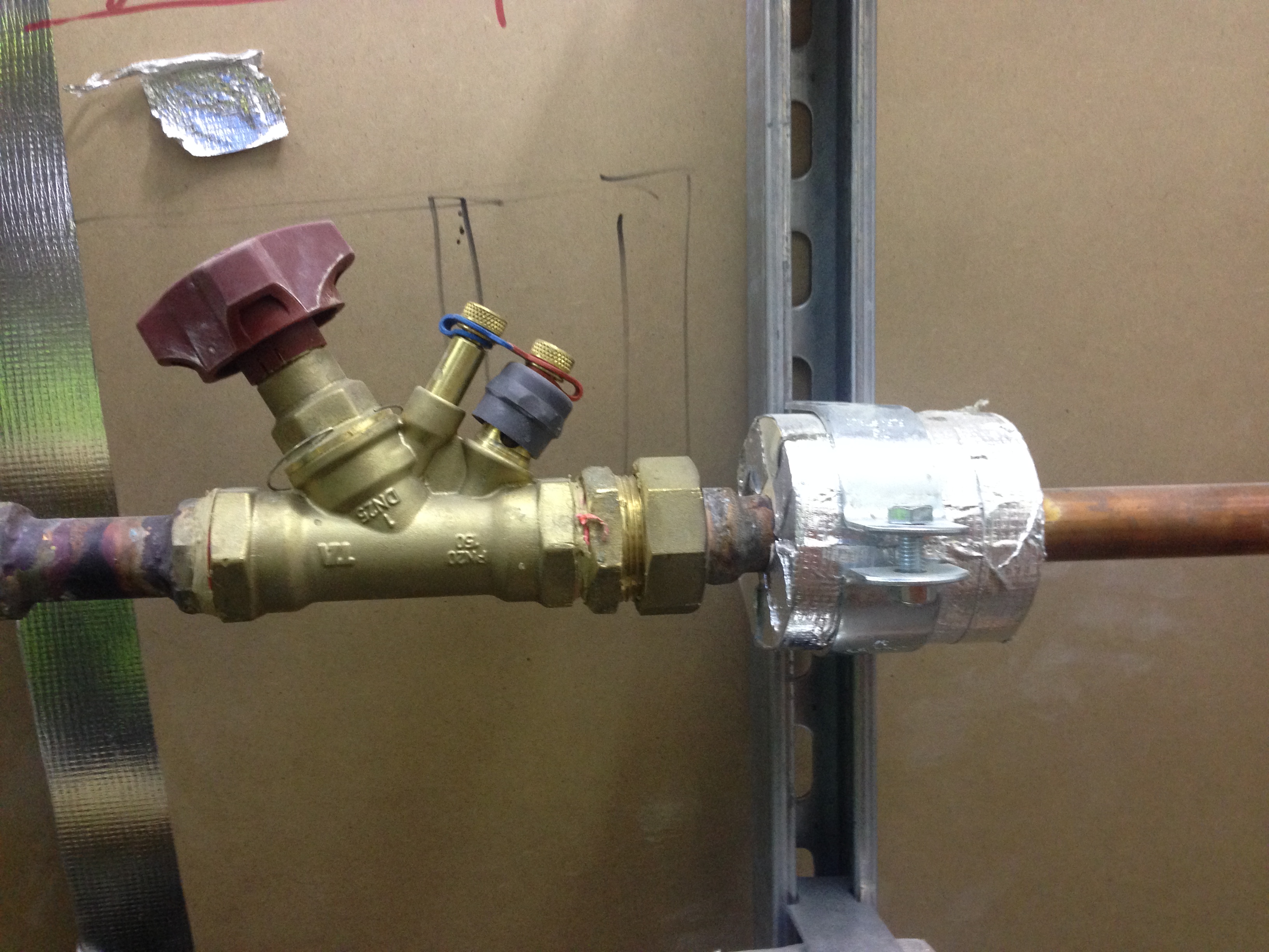
Plant Room 8 Level 2 – flow is right to left. Both upstream (right) and downstream (left) are out of limits. You can see on the right between the lagged fixing and valve that the pipe dia changes from 12.5mm to 20mm. What’s most likely happened here is that they have used the wrong dia valve (pictured is 20mm) for the pipe line of 12.5mm so had to weld in a piece of 20mm pipe to make it fit. Also, just at the edge of the left of the pic the pipe dia changes again – inside the required 5 x dia = 100mm, so out of limits again.
Fredon’s response was that they followed the guidelines as per the Consultant’s Advice Notice (CAN). We pointed out the dims as per CIBSE and TA (the reason we needed to double check TA data sheets) and reiterated that this is what they should be working to not solely the CAN. The CAN is just a notice explaining what work needs to be carried out but must be used in conjunction with documented design data – which they clearly didn’t do.
The Solution
The solution is easy – JHG have rejected the work and rework is required but this time in line with the CIBSE code and NDY Spec.
Commercial Aspects
Fredon will take the hit. There is no recourse as the work is out of scope and has been rejected. A separate notice has been raised to that effect.
