Archive
The invention of looking
Another day another project. I have started to become increasingly involved in ‘Building 2001’ in Harrisburg, which is the home of the enormous Eastern Distribution Centre (EDC). I say increasingly involved, though yesterday I narrowly avoided arrest, more about that later. The building is pretty large, mainly dominated by a warehouse but with an admin section about twice the size of Denison strapped to the side. The current contract is to replace the roof, change some lighting, improve the ventilation and replace, more or less like for like the HVAC system. And so far the most important lesson I have learned is: Avoid dealing with refits wherever possible! I will expand.
To follow on from Guz’s theme of invention and Rich’s point on people actually leaving their desks to look at stuff. Two things this week have lead me to believe that the designers didn’t actually bother coming to do a detailed survey of this huge building before cracking on with their designs and just assumed the as built drawings were complete and correct.
The building has three plant rooms. The main plant room has the steam distribution and the main elements of the chilled water distribution. The other two smaller plant rooms each service their respective admin floors with an Air Handling Unit (AHU) and some minor switchgear. As it begins to get warm here we are starting to cobble together a temporary system whilst we wait to get the main cooling system on line. So as we were talking through the system in a meeting, so at least better than a chance conversation, the contractor stated that the plant room housing the ground floor AHU was getting really hot; suboptimal in cooling season. We asked why and he said it was obviously because of the two condensers that were stationed in there from some retrofit air conditioning systems.
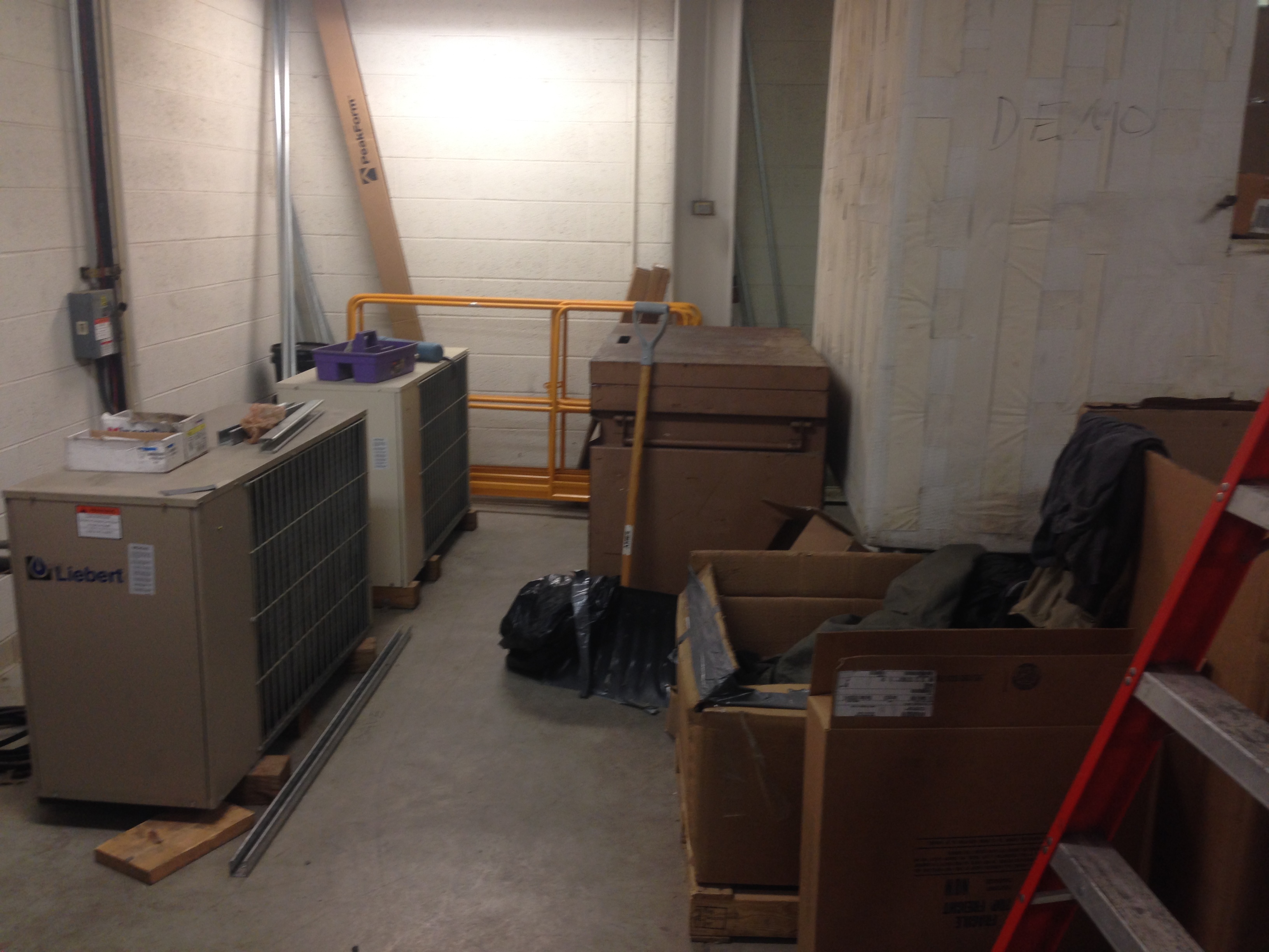
Just heating the room that is trying to cool the rest of the floor. Outside is a mere 20′ away.
Some pipe hunting later and we found that these fed two computing classrooms that had obviously required extra cooling at some point in the last 10 years. Checking the contract these aren’t to be replaced. Now I haven’t checked the as built drawings, but I don’t need to because the photo above clearly shows exactly where these condensers are. So my question is, which idiot put them there and which idiot decided to leave them there in a comprehensive refit of the building’s mechanical equipment. My conclusions are that it comes down either to incompetence or money. But, based on the next example, it is difficult to say it was just a cost saving measure as incorporating a couple of extra outlets into a room to increase the cooling capacity would have been pretty cheap in the grand scheme of things: I think the designer didn’t know they were there.
So to observation two. The biggest reason the air conditioning system is not running is that the cooling towers (condensers) on the roof aren’t connected. This is because someone forgot to design the structural steel to hang the pipes from. So due to the rising mercury we have hired a trailer mounted condenser, complete with pumps. So the question is merely what size?
After a chat between the contractor, mechanical engineer and myself we decided on 500 tons, ordered it and it arrived. When it turned up we proudly went out to observe our $40,000 a month lease and the installation electrical engineer asked when the other one was coming? And that was when email tennis started.
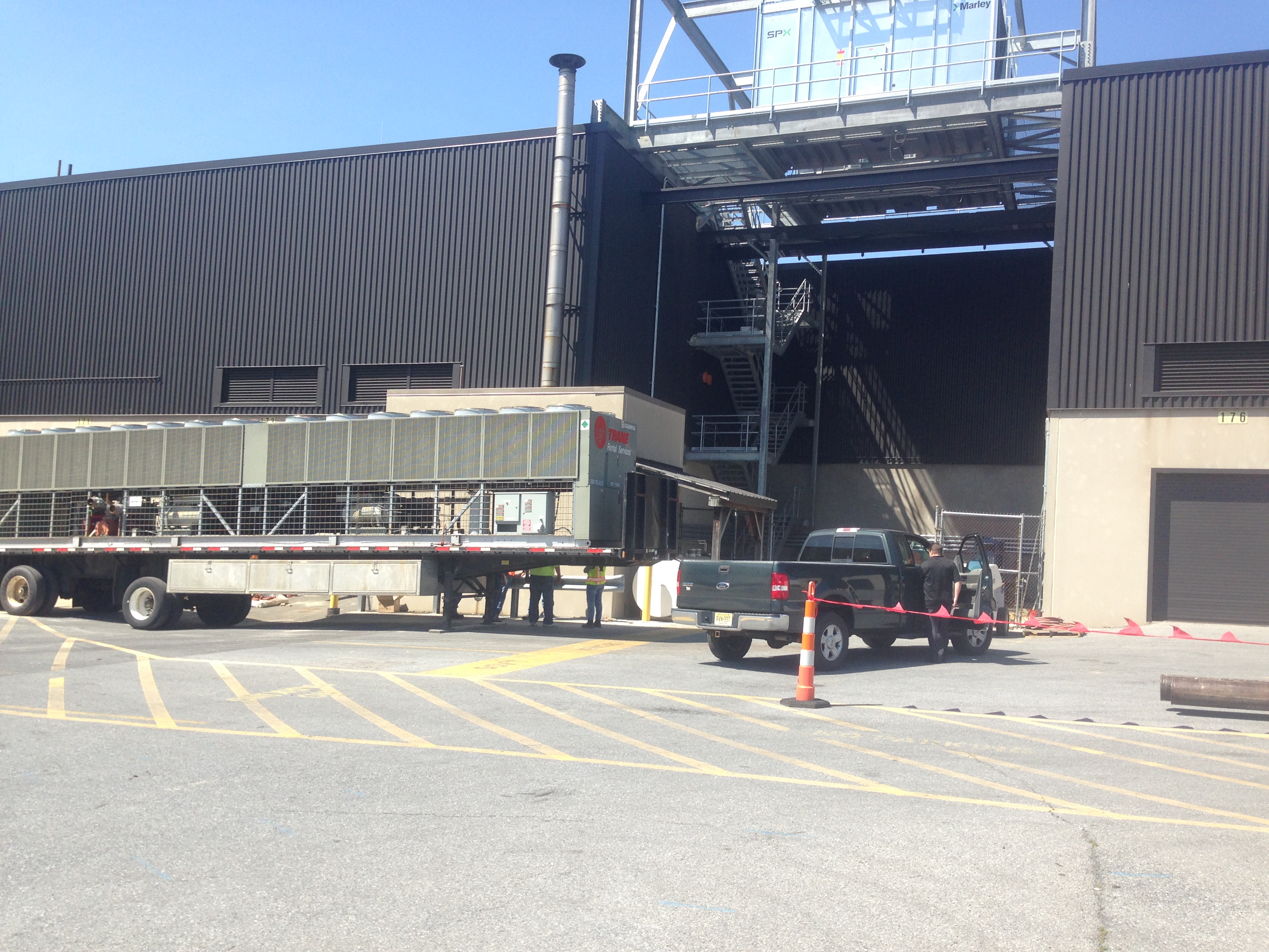
The 500 ton temporary system in the foreground. The new chillers (1300 tons) up high.
The original system was designed at 1800 tons (2 x 900 ton cooling towers) and in the design guide produced by the design consultant there was a magical figure of 1220 tons as the load. The new system is designed at 1300 tons and so the installation decided 1000 tons was the minimum possible. The installation engineers therefore stated that our temporary chiller would simply not be large enough and kicked up a stink with explanations of the old system working flat out and hardly being able to keep pace.
So the proof will clearly be on Tuesday when the system is turned on and the temperature is set to be in the high 80’s for the week. However, I will justify our decision now. The contractor has worked on this building for the last 2 summers and swears that there has only been one cooling tower operating at a time; indeed last year one of them was out of service. He also said that when he removed the old cooling towers he’d called the manufacturer with the serial number and asked the size: 600 tons (for some reason it wasn’t on the nameplate). Additional factors are a number of smaller AHUs have been removed and the temporary power supply wouldn’t run a 750 ton unit. When designing the controls, before my time, we had been told the permanent 1300 ton system was to give redundancy, as out here everything has redundancy.
Conclusions
Having read the design handbook for this project nowhere was there actually a calculation of the load, just an assumption with no justification. Remembering back to the design projects writing why an assumption was made seemed frustrating as it got in the way of moving onto the next calculation. However, the reasoning behind these assumptions are vital in the real world for someone to understand your calculations so they can make decisions later down the line; especially if the situation changes. This applies to references too as a reader can understand your thinking better if they can trace it back to source. It the light of contradictory evidence empirical evidence should take precedence.
As built drawings are not 100% reliable. They may be but it depends on whether someone has the time or funding to keep them up to date. In the EDC there are a number of different organisations with little pots of money doing self help projects all the time so some might not even know where to get hold of the master set of drawings; if there even is one. Thinking forward to doing DfID style projects the odds of getting BIM are pretty long! Therefore time spent on recce…
Oh and my near arrest. Well despite having been working in this building for three weeks it appears I don’t have clearance. Yesterday I tried going in through the main entrance and was told my name wasn’t on the list by the DLA Police. The building is about as secure from entrance as a sieve is from water and holds nothing remotely of interest to a thief or spy but rules is rules. It turns out I just need to present a letter that I am not allowed to see the contents of to the head of security and it should be fine! I can only imagine the pain Brad has been through and I’m pretty glad that the engineer I work with is the base commander’s wife as that probably prevented bracelets.
Making it up
This week’s blog is about stuff that doesn’t fit…
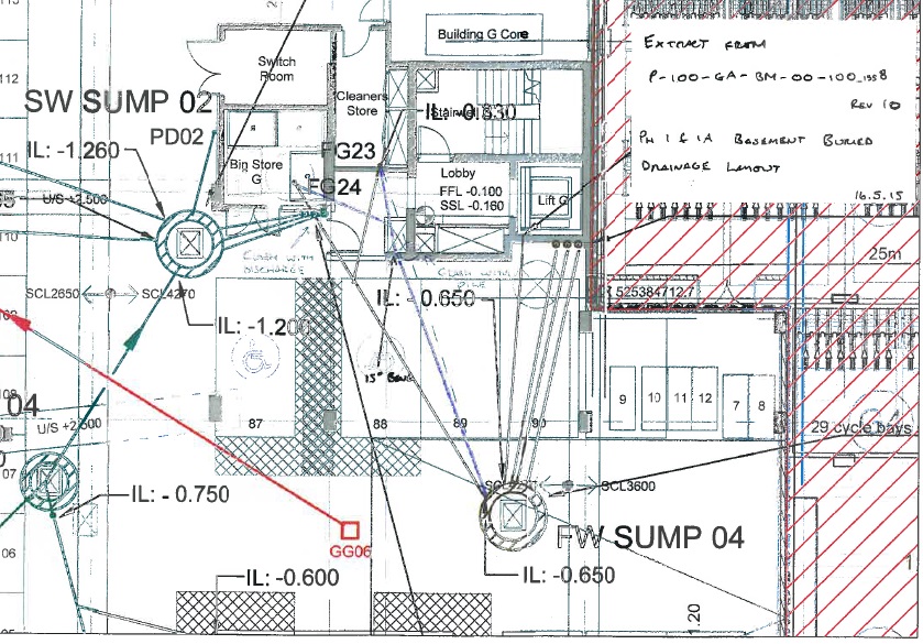
We’ve got a channel for an ACO drain in the steel, and a pipe for the ACO drain, but the two don’t line up. I checked the setting out for the pipe, it was in the correct location according to the setting out information from Arup. I then checked the channel in the steel. It too was in the correct location according to the setting out information from Arup. It turns out that if you overlay the structural drawing and the drainage drawing they don’t line up:
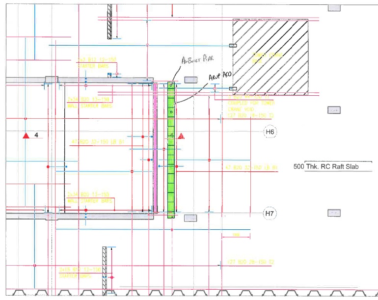
Pink shows structural design location for ACO drain, Green shows the drainage design location
We’ve solved the problem with the imaginative use of a 90 degree bend (which are actually 87.5 degrees, but that’s another story) and a T junction.

I would dearly love this to be the only such balls up, but it’s not. We had a drainage run that should be a straight pipe with a y to a second drain. It couldn’t go there as it would clash with the discharge pipe for another sump. So we tried it the other way round and that clashed with a pile head. So we’ve had to bend it round the pile in order to get it in.

Both the drainage design and the structural design are both done by Arup, so yet more examples of an organisation sending out contradictory information.
But unlike previous examples where it was because people in open plan offices sit next to each other and yet still prefer to send emails rather than have any form of human contact, this would appear to be mostly due to one man thinking his area of responsibility is more important than anyone else’s and assumed that everyone would make their designs fit his. The structural engineers assumed they were the most important and so didn’t bother to check.
We’ve solved all of these problems but it does begin to raise concerns about the competency of the people who design these things. Neil often asks about how on earth they designed something as complicated as the Shard. I fear the answer may be: “They just made it up!”
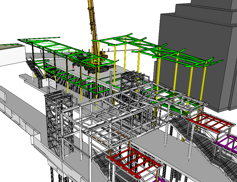
It’s not all bad news though. Our 5th tower crane is up and the site is really moving now. PCH are here only in name but the blokes are very much here in person so we’re progressing nicely!

My Passive is Active and piles might get pre-bored!!!
So yesterday I ended up chatting to Richard and John for a while with a question about how pre-boring affects the resistance of sheet piles in clay and how to model it in WALLAP. As I suspected the answer wasn’t a simple one!
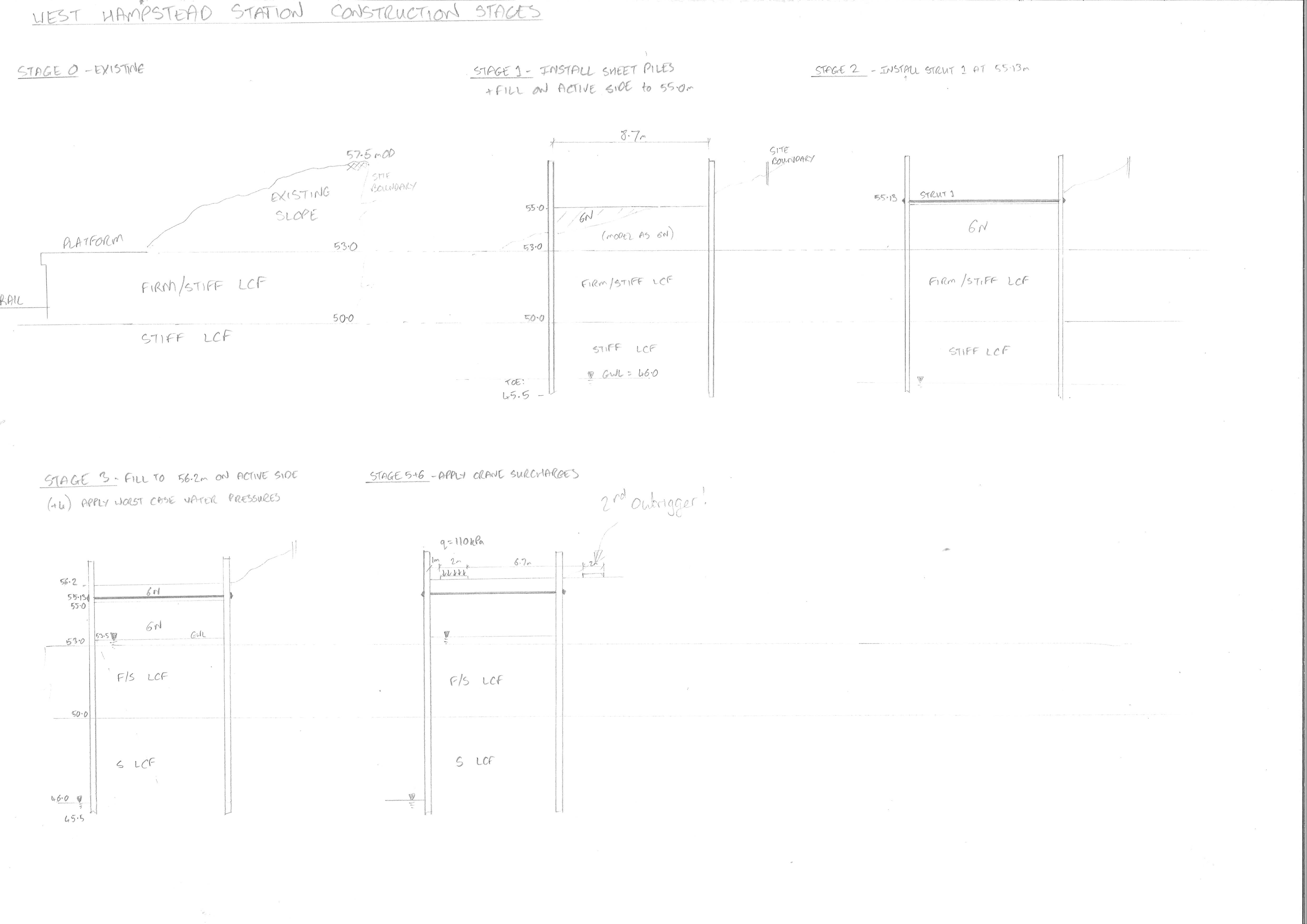
The retaining wall is part of the station redevelopment at West Hampsteadand were are designing a cofferdam that will act as the base of a new station building. It will also need to accomodate a large crane during the building of a new footbridge.
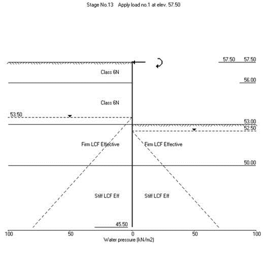
The ground consists of firm to stiff London Clay overlying stiff London Clay and we will use 6N (Granular Fill) inside the cofferdam. I used WALLAP to model the wall nearest the track to obtain the moments and shear forces and strut forces to enable us to design the ties between the the walls of the cofferdam.
Because the clay is stiff, it may need to be pre-augered to loosen the ground prior to piling. This has an effect on the stiffness of the surrounding soil and vertical resistance. The question was-by how much? After a long conversation with John I established that seeing as stiffness is unreliable squared then your guess was a good as mine! The solution was to do a sensitivity analysis by adjusting the stiffness parameters in WALLAP and see how much it actually mattered. The result wasn’t too significant so we have stuck to values of half of the undrained shear strength and half the stiffness values. We’ve also suggested water-jetting instead-has anyone had any experience of it on site??
Active and/or Passive??
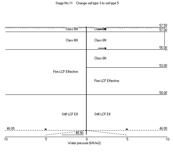
The next part of the problem was modelling the far wall of the cofferdam. In theory because is was in level ground it is acting as a deadman anchor to the main wall using the ties. The ties forces were modelled as horizontal loads on the passive side.
Life would be straightforwards if that was simply the case but because that side also the active side of the main wall we have a problem where the two wedges interact. Since this is quite a common problem I thought there would be lots of literature on it but I was wrong! The BS CoP for Earth Retaining Structures simply says move your deadman further away outside of the active zone:
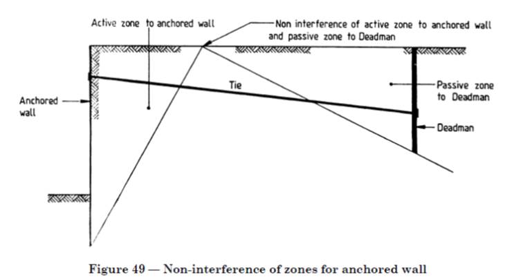
But we can’t do that as our second wall can’t be moved further out and it will become the piles for the building. So we have ended up just adjusting the rigid boundaries in WALLAP to reduce the amount of passive resistance available. It is a bit concerning that there isn’t much written about this when you think about the number of walls behind walls that are holding up various structures everywhere!
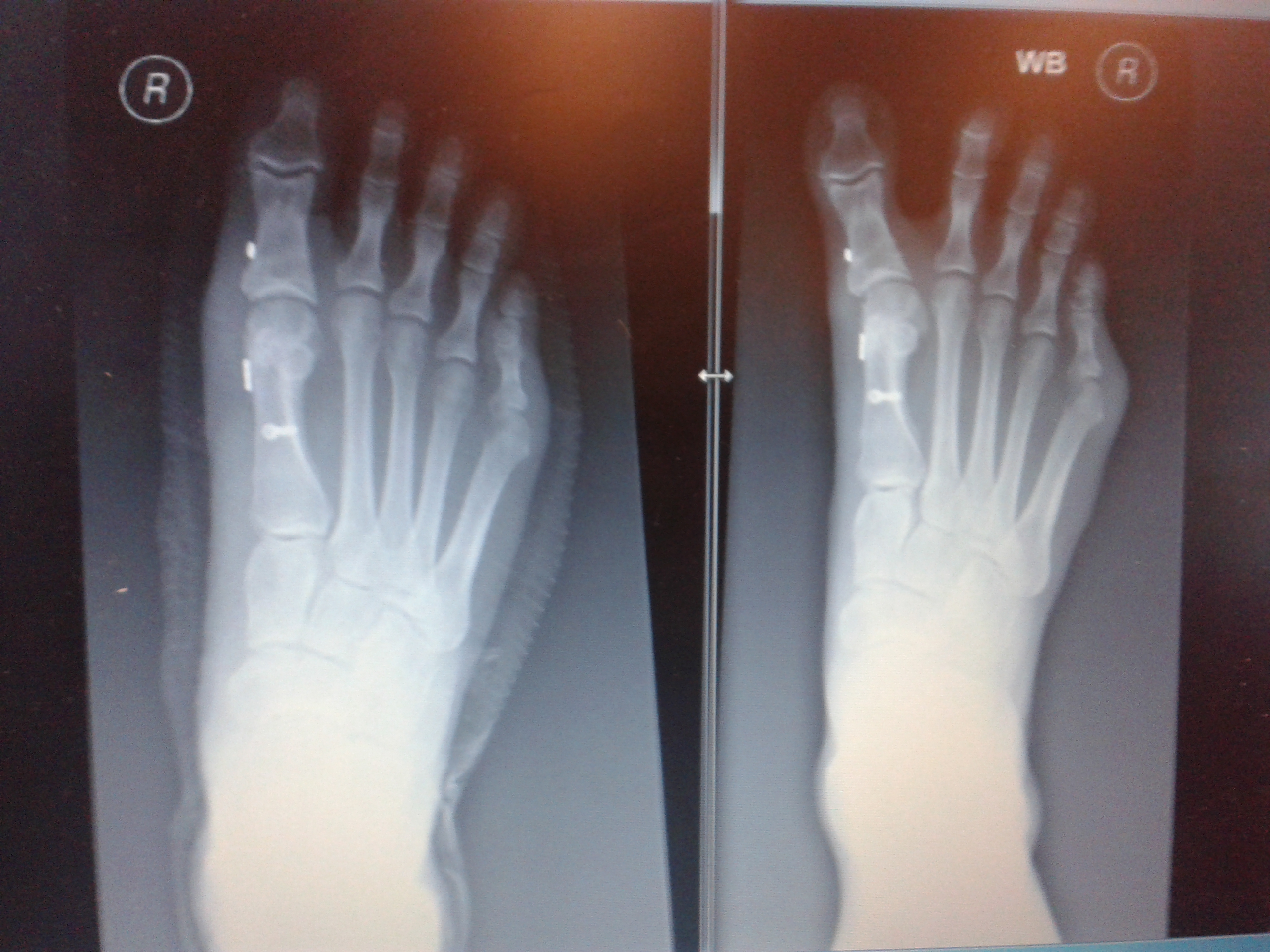
Unfortunatley it looks like my foot doctor didn’t do his maths on the forces that my foot goes through as my podiatrist sent me back to him for a review as my big toe looks a bit wonky again. You don’t need to be a doctor of engineer to realise that the piece of wire between the two metal buttons that goes between my big toe and the next has either snapped or cheese wired through the ligament holding it in place. The Xray on the left was post surgery in Jan and the right was last month. It looks like it will be 3rd time lucky with surgery on this foot and next time he will use wire meant for holding together shoulders and I get a month in my air cast boot 😦
Some additional info to add:
Well I think I had already done what John has said by drawing up this sketch of the Active wedge of the front wall (orange) and what is left available to become the passive wedge (pink) since we have a deep anchor we will have more passive resistance as shown by the pink dashed line too. I had a play around with WALLAP by moving the passive rigid boundary and it didn’t affect things too much. I will also have a go at making the ground slope on the passive side to see what that does.

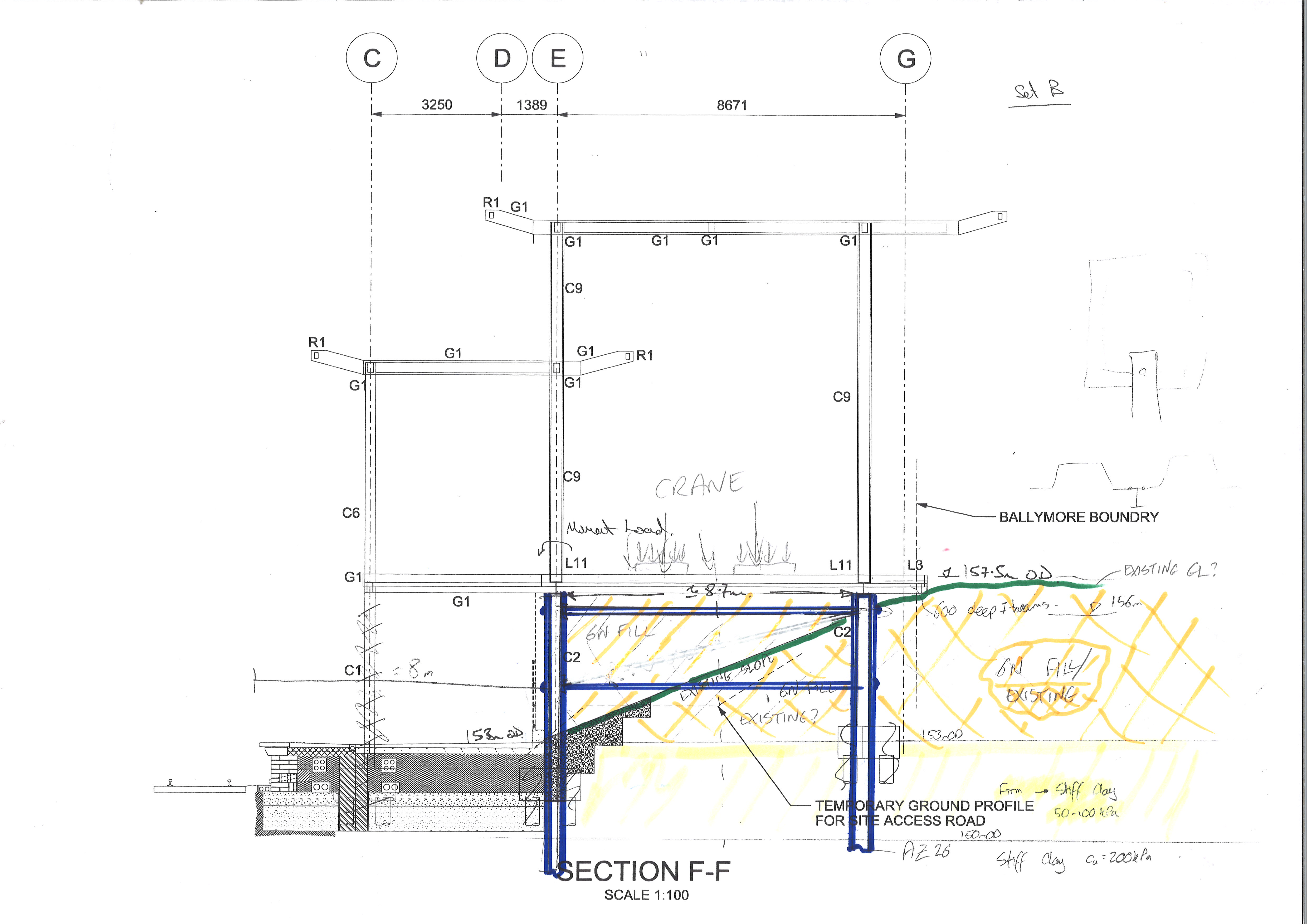
In response to Howards points here is a section view to help explain the bigger picture. The rear wall will become the piles for the back of the building and the site boundary is just behind it so we are restricted on anchor systems. Our worst case loading is the crane in the temporary condition so once the slab is in place and it becomes a building it ends up retaining less as currently the slab is suspended.
The railway team then decided to throw a spanner in the works and they now want an attenuation tank for surface water just below the slab so we have had to lower the crane and set up a new model. On drawing out the construction sequence I have found a much bigger spanner to lob around as I’ve noticed that their crane doesn’t fit!! I’ve just sent the email that no-one wants on a Fri afternoon saying that not even a crane 1/5 the size of what they need will fit in our cofferdam and they might struggle with the site boundary too!!