My Passive is Active and piles might get pre-bored!!!
So yesterday I ended up chatting to Richard and John for a while with a question about how pre-boring affects the resistance of sheet piles in clay and how to model it in WALLAP. As I suspected the answer wasn’t a simple one!
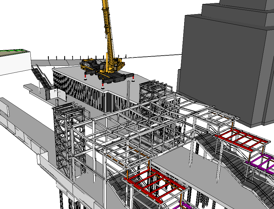
The retaining wall is part of the station redevelopment at West Hampsteadand were are designing a cofferdam that will act as the base of a new station building. It will also need to accomodate a large crane during the building of a new footbridge.
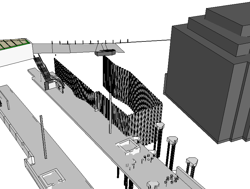
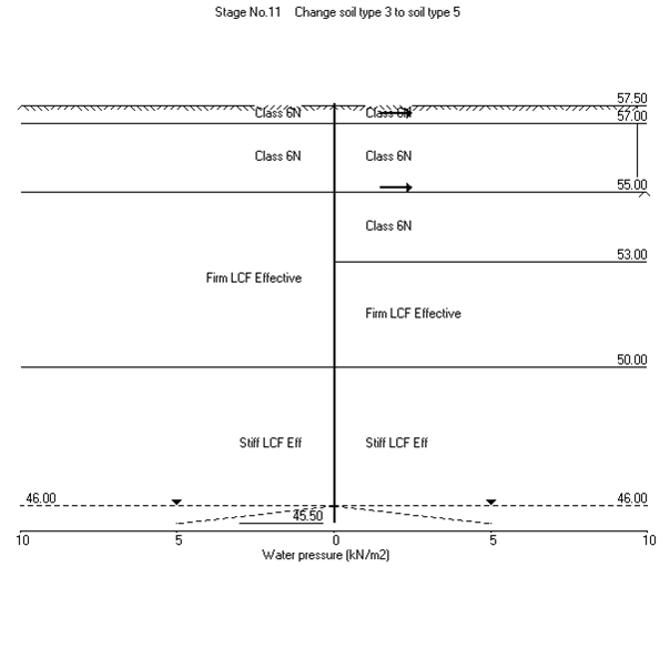
The ground consists of firm to stiff London Clay overlying stiff London Clay and we will use 6N (Granular Fill) inside the cofferdam. I used WALLAP to model the wall nearest the track to obtain the moments and shear forces and strut forces to enable us to design the ties between the the walls of the cofferdam.
Because the clay is stiff, it may need to be pre-augered to loosen the ground prior to piling. This has an effect on the stiffness of the surrounding soil and vertical resistance. The question was-by how much? After a long conversation with John I established that seeing as stiffness is unreliable squared then your guess was a good as mine! The solution was to do a sensitivity analysis by adjusting the stiffness parameters in WALLAP and see how much it actually mattered. The result wasn’t too significant so we have stuck to values of half of the undrained shear strength and half the stiffness values. We’ve also suggested water-jetting instead-has anyone had any experience of it on site??
Active and/or Passive??
The next part of the problem was modelling the far wall of the cofferdam. In theory because is was in level ground it is acting as a deadman anchor to the main wall using the ties. The ties forces were modelled as horizontal loads on the passive side.
Life would be straightforwards if that was simply the case but because that side also the active side of the main wall we have a problem where the two wedges interact. Since this is quite a common problem I thought there would be lots of literature on it but I was wrong! The BS CoP for Earth Retaining Structures simply says move your deadman further away outside of the active zone:
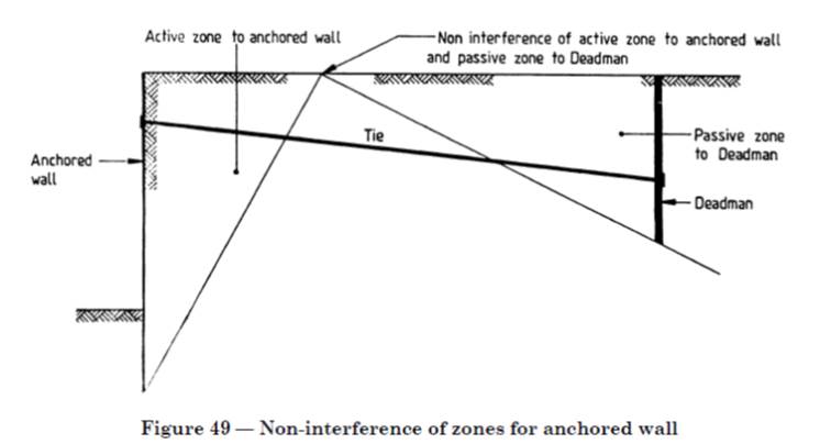
But we can’t do that as our second wall can’t be moved further out and it will become the piles for the building. So we have ended up just adjusting the rigid boundaries in WALLAP to reduce the amount of passive resistance available. It is a bit concerning that there isn’t much written about this when you think about the number of walls behind walls that are holding up various structures everywhere!
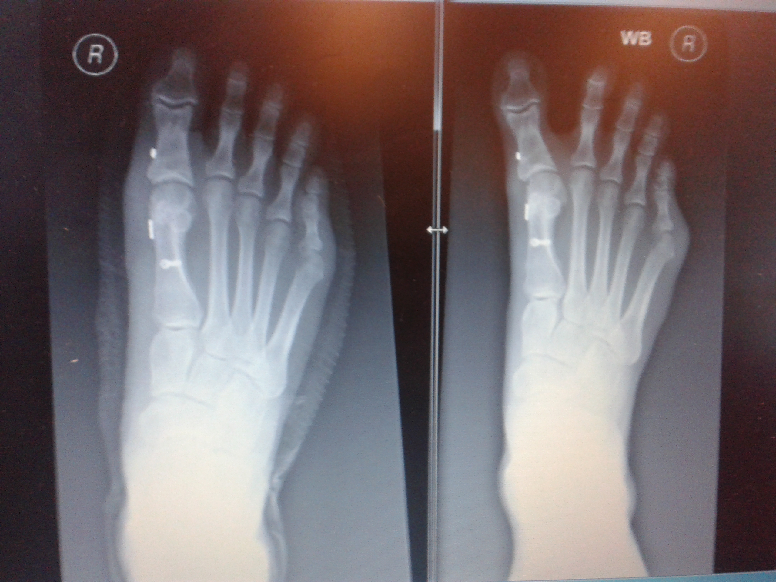
Unfortunatley it looks like my foot doctor didn’t do his maths on the forces that my foot goes through as my podiatrist sent me back to him for a review as my big toe looks a bit wonky again. You don’t need to be a doctor of engineer to realise that the piece of wire between the two metal buttons that goes between my big toe and the next has either snapped or cheese wired through the ligament holding it in place. The Xray on the left was post surgery in Jan and the right was last month. It looks like it will be 3rd time lucky with surgery on this foot and next time he will use wire meant for holding together shoulders and I get a month in my air cast boot 😦
Some additional info to add:
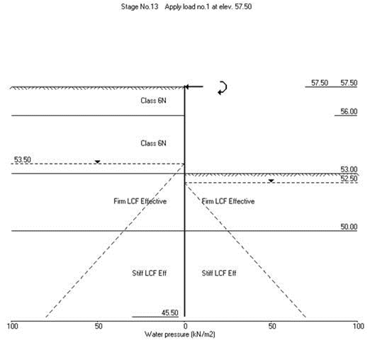
Well I think I had already done what John has said by drawing up this sketch of the Active wedge of the front wall (orange) and what is left available to become the passive wedge (pink) since we have a deep anchor we will have more passive resistance as shown by the pink dashed line too. I had a play around with WALLAP by moving the passive rigid boundary and it didn’t affect things too much. I will also have a go at making the ground slope on the passive side to see what that does.

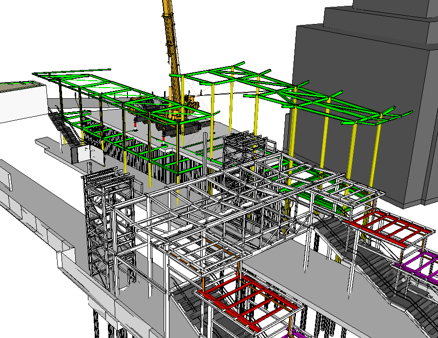
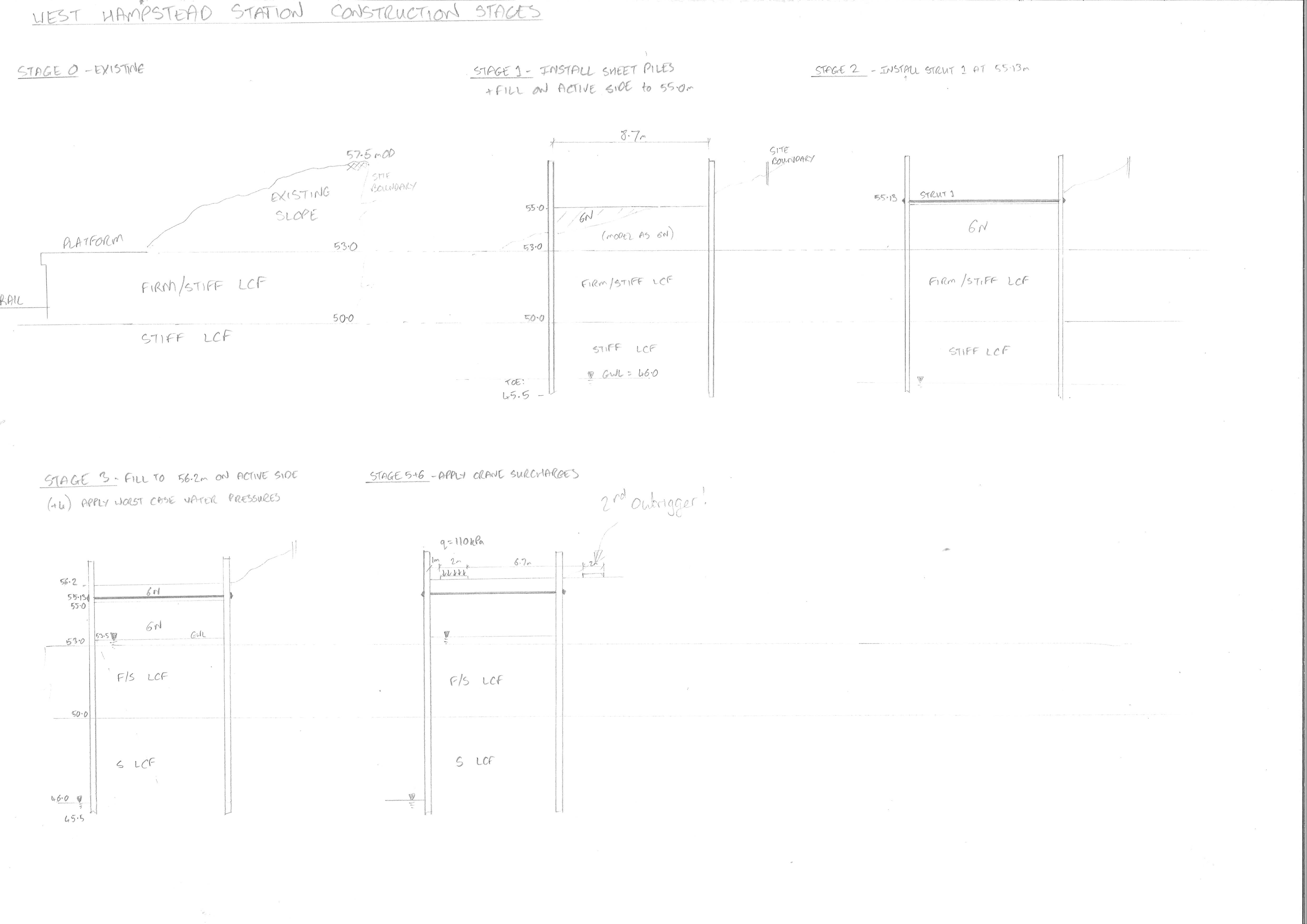
In response to Howards points here is a section view to help explain the bigger picture. The rear wall will become the piles for the back of the building and the site boundary is just behind it so we are restricted on anchor systems. Our worst case loading is the crane in the temporary condition so once the slab is in place and it becomes a building it ends up retaining less as currently the slab is suspended.
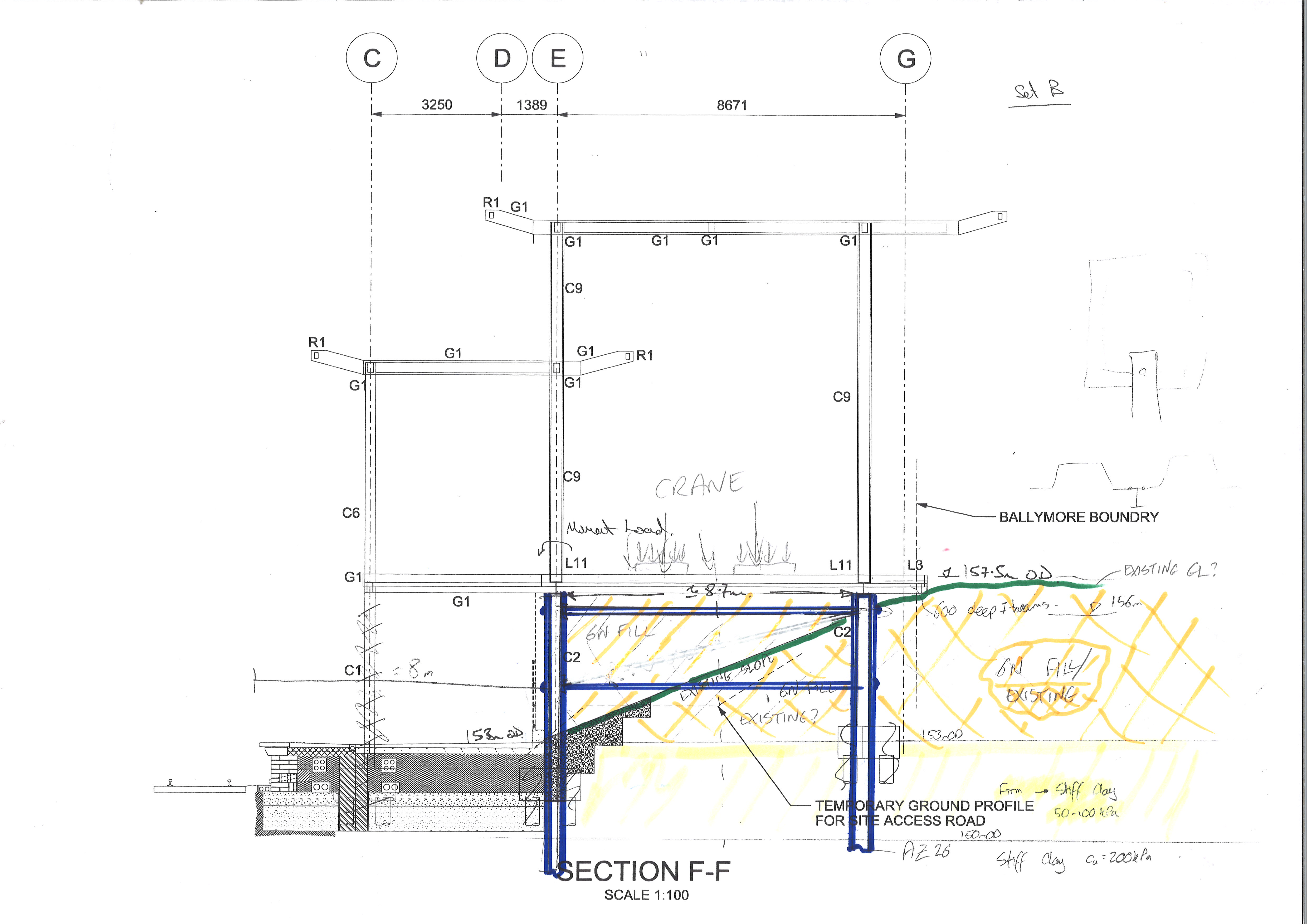
The railway team then decided to throw a spanner in the works and they now want an attenuation tank for surface water just below the slab so we have had to lower the crane and set up a new model. On drawing out the construction sequence I have found a much bigger spanner to lob around as I’ve noticed that their crane doesn’t fit!! I’ve just sent the email that no-one wants on a Fri afternoon saying that not even a crane 1/5 the size of what they need will fit in our cofferdam and they might struggle with the site boundary too!!

Well let’s see. Yes I’ve used jetting they weld jet pipes to the piles and then inject water under high pressure to the toe as the drive tightens; I’d been told it was more for coarse grained than fine…but do tell.
Your second problem is a logic problem.
Let’s start with the STR .And let’s assume that the ( compatible ) movement in the front and rear wall is insuficinet to bring the soil to failure; it means that the state is somewhere above active and below passive in this zone; the front wall experiences this stress and the anchor system and the wall are designed not to fail structurally. A decent WALLAP model would be a stiff anchored support to enable above-active respose high in the wall.
The deadman model would be a guessed rear wall depth and the implied anchor force ( form aboce) applied as a pull; look at the implied development of stress to the front of the anchor and checking that this was not too far outwith the rear stress to the rear of the non-failed wall.
So with this anchor and wale system we look at the GEO states.
The limit state for the front wall is that the displacement ( probably about 0.001H) brings the front wall to the active state. The stress state is active – possibly all the way to the front of the anchor and the limit on the rear is active- this gives no net ability to anchor!
SO more, likely with a half decent geometry,is that the rear anchor is being pulled towards a piece of sloping ground, where the slope is pi /4- phi’/2 to the vertical( ie where the implied active failure surface cuts)- this is then the max tie you can get out of the anchor for the limit state check of the front wall.
Wen you run the limit state of the rear block thorugh you will relaise that the strained required to get it to passive on the front will imply that the (compatible) movement of the front wall brings us back to the same problem – active behind the front wall and passive in a sloping site to the front of the dead-man
and someone said ….absolute CPR gold this !
Interesting stuff Ange. Not really answering your Q, but going back a step. Have you considered other anchoring options if tieing to a deadman is proving potentially high risk in design and you can’t move it further back – if so, why were they eliminated? By the looks of it I take it that you want to keep the foot of the wall as close to the top of the water level as poss; if not, then why not go deeper thereby increasing the passive forces and decreasing the moment about the base? Conscious that active will still increase (Ka to a lesser amount than Kp), potentially increasing the problem? I take it there must be a a lot of trial and error in in getting the right depth, in order to get the optimum balance between passive & tie forces vs active.
Great blog Angela. All looks like a toe problem to me; based on the xrays that is. Earthworks I’ll leave to others ;-).
I’ve added some bits above to answer your questions.