Archive
Designing for Tendor.
I have been on site now for nearly a month and am quickly picking up tasks from all over the place. One of the main items I have been put in charge of is a 6km pipeline running from the Spencer Gulf to site, designed to carry seawater in and a separate pipe to return the brine water. The pipeline was designed by KBR, procured by John Holland (JH) and is in the process of being installed by York Civil. Up to now no one from JH has taken any ownership of the pipeline so it seems a good chance to actually contribute something worthwhile to the project. I have been looking after it for two weeks now and these are some of the issues I have come across:
Design and Procurement
The pipe itself and all of the fittings are to be procured by JH and free issued to York Civil. The JH team responsible for this procurement is based in Brisbane and has worked directly off the KBR drawings to procure all of the items. This has led to a number of issues, firstly individual responsible for procurement is not subject matter experts or an engineer; this has contributed to key items being missed in the procurement process including all of the gaskets and bolts. Secondly the initial design used for the tender process appears to have been done using geographical data and aerial photography this has resulted with a design that is not suitable for the ground and as a result considerable redesign is being conducted on site, which will result in some serious variation orders from York Civil. In addition these changes have resulted in many of the items procured already being inadequate or insufficient for the new design, some of which have long lead times, such as the pipe itself which has come from Turkey. This leads into the third point which is that the procurement teams method seems to be to request quotes from various suppliers; they then choose the cheapest supplier. It appears that no consideration is given to the suppliers’ location and delivery times. For example six automatic air valves are being shipped from Israel taking 8 weeks to arrive despite there being manufactures in South Australia.
Stakeholders
The pipeline runs across some private land, through existing easements, however the landowners were up aware of the easement. Currently they have ourselves putting a pipeline through it and the local power supplier constructing an overhead power line, to get power to our site. This has resulted in a re-route of the pipeline and narrowing of the working corridor. One of my tasks has been to construct a dilapidation report along the route in order to ensure compliance with guidelines laid down by the local environment agency.


The pipeline beginning to be lifted into place.
Construction
The drawings issued for construction along with the specifications have resulted in a design that is almost impossible to build. For example, the design requires a compaction to be provided by mechanical means around the pipes in layers of 150 mm. Once the pipes are in the trench there is insufficient space to fit equipment to compact or to test the levels of compaction. The designers are up willing to renegotiate the levels of compaction because the specification of the pipe has already been reduced by JH in order to reduce the cost. At the moment we are working with the sub-contractor to develop some trial areas to establish if the desired levels of compaction can be met by any other means.
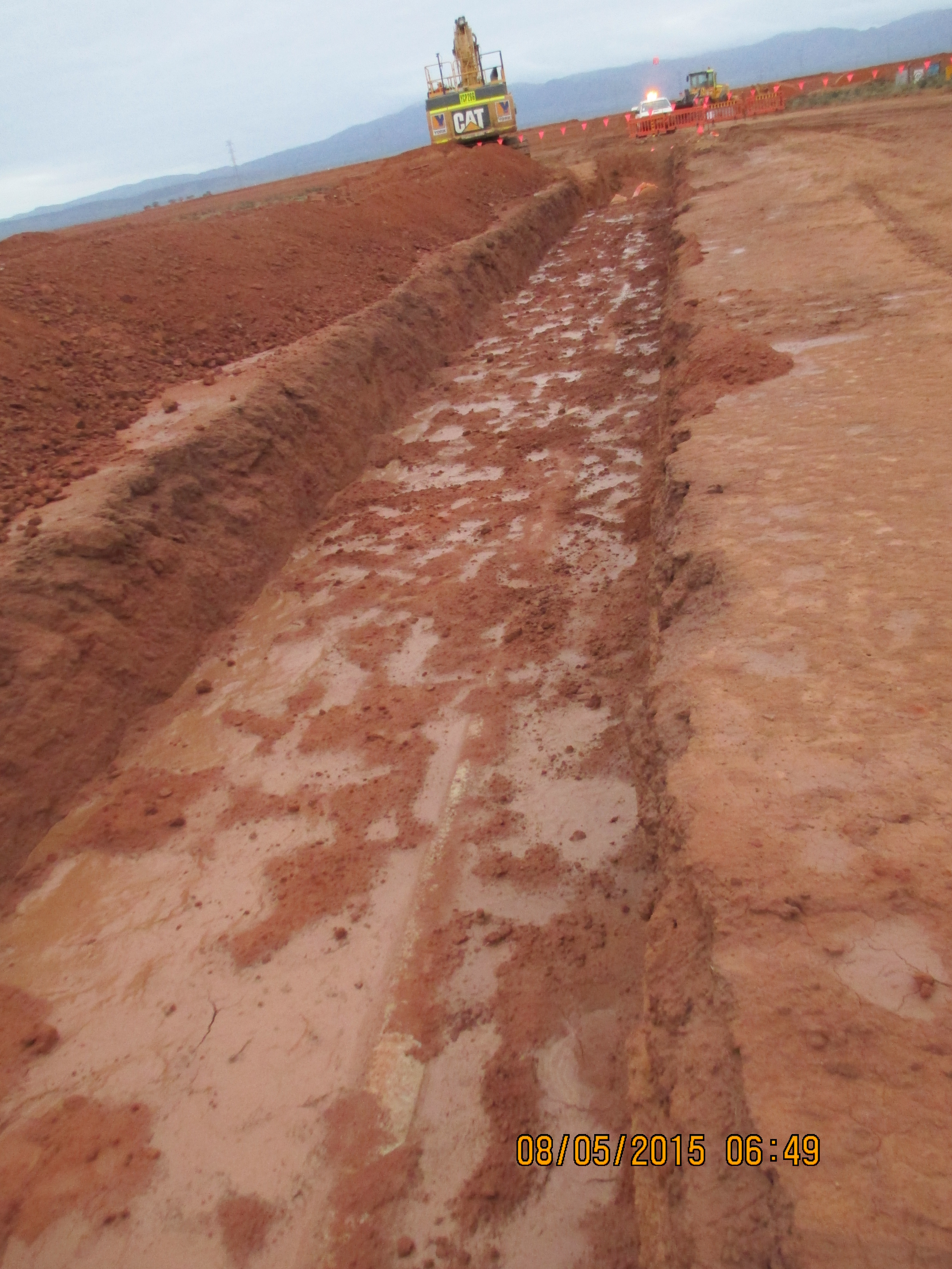
A shot of the trial compaction area- walking in and damping down with water.
Linked in to the compaction of the pipes is the requirement in the specification for the subcontractor to check the internal diameter of the pipe following compaction. At the moment the subcontractor have not found a method of how to do this; the pipe has a number of bends so a laser cannot be used. Again because of the reduction in the specification of the pipe the designers are not willing to remove this requirement.
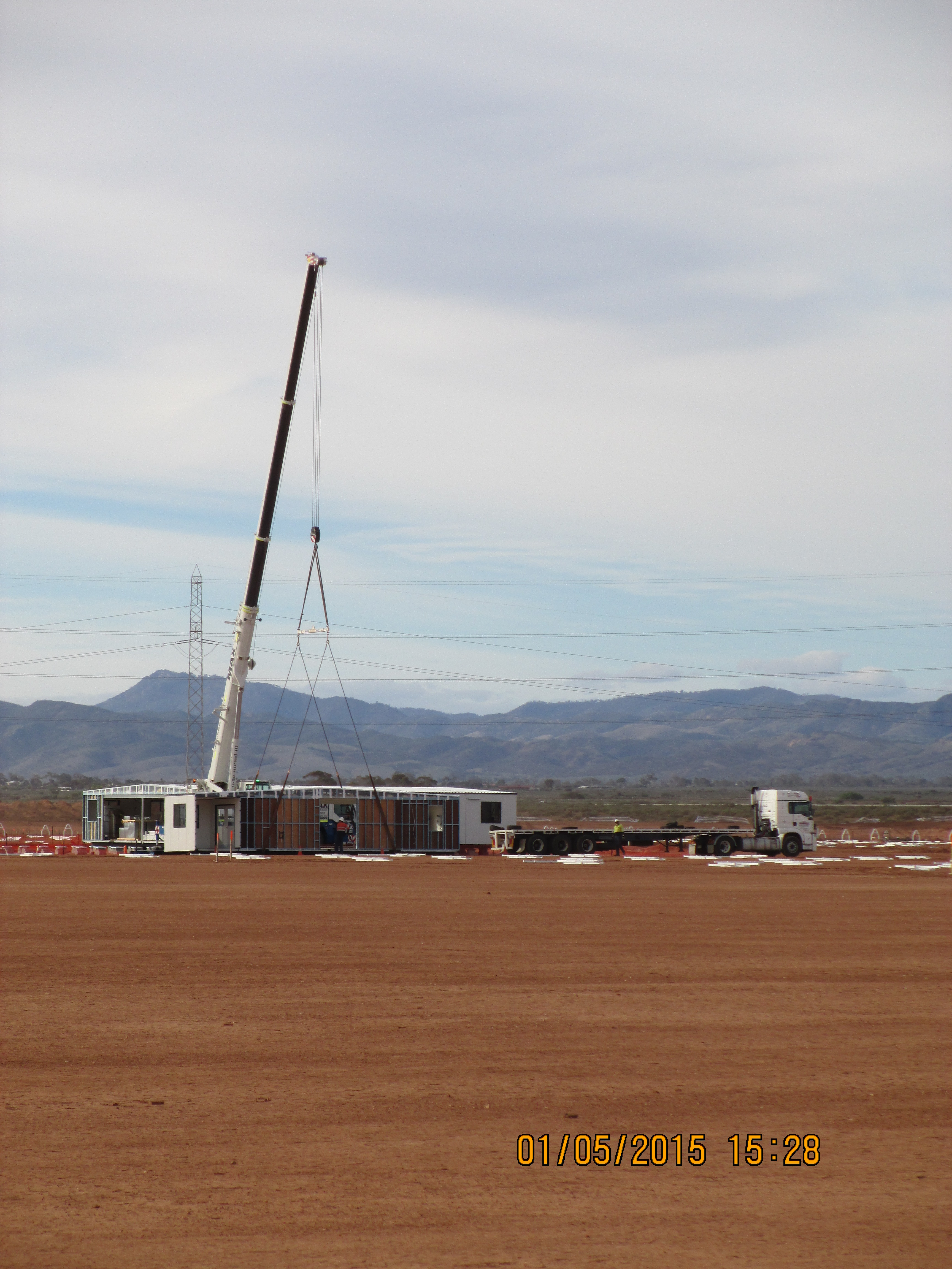
One of the other items I was running with was installing of 16 modular buildings that will form the permanent offices and amenities on site.
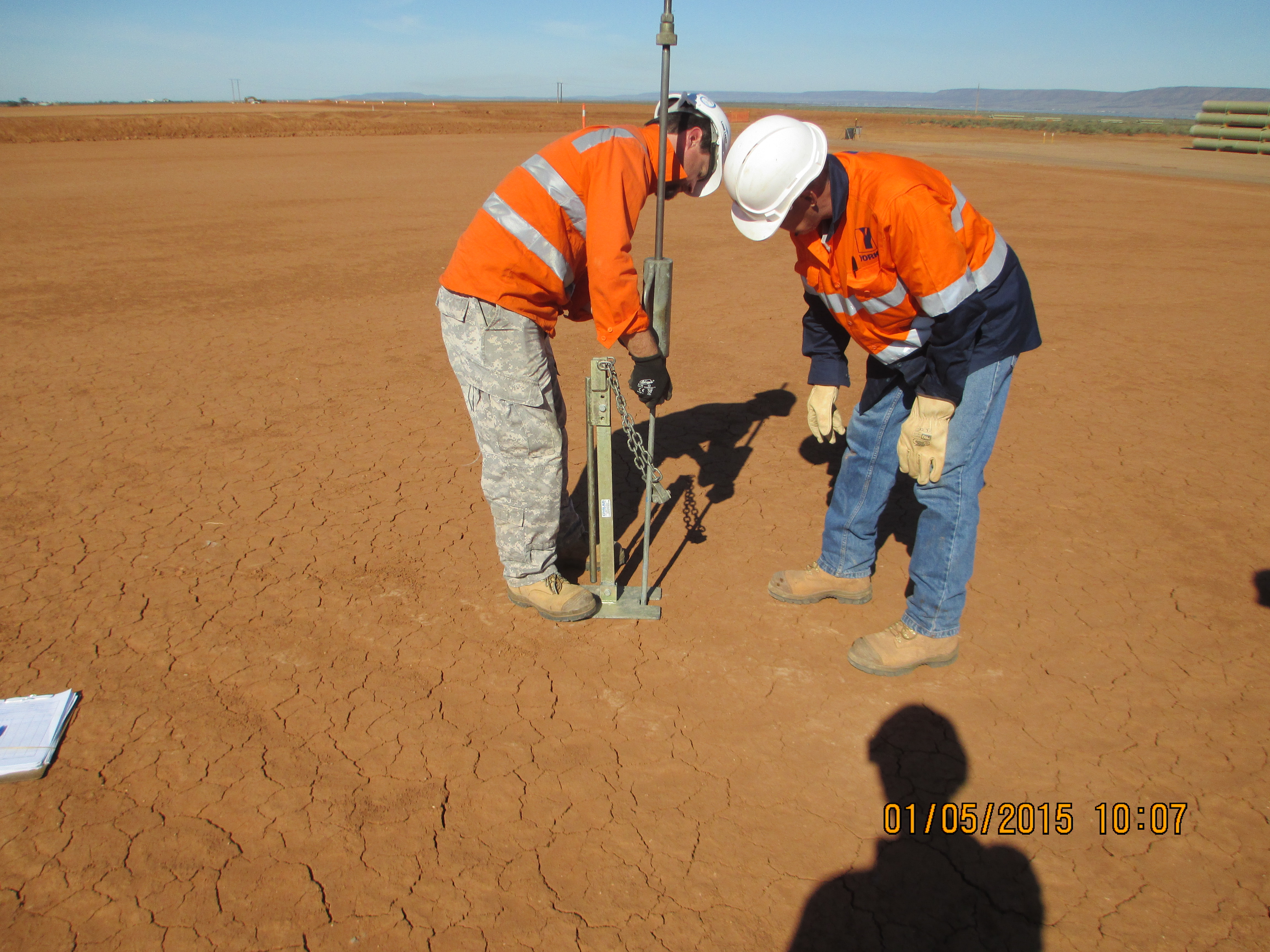
I thought I would add this for all you civils out there, seems to be some advanced version of the cone penetrometer, I did ask the guys how it worked, but they were just working it out for themselves!
Site Two Fifty One – Some Engineering Thoughts
Tower cranes. If a tower crane were to fall over and land within 4m of a railway, it must have its foundations checked 3 times (initial design, internal check and external check).
As part of the risk mitigation requirements Network Rail say the crane has to have its working load reduced to 75% of its capacity. Generically this seems sensible – reduce the load to reduce the possibility of the crane falling over.
Due to the location of the railway in relation to the tower crane, it is clear the adjacent buildings prevent the crane from slewing onto the track when loaded. Therefore any variable load would act in a restoring fashion, reducing the possibility of the crane overturning towards the railway.
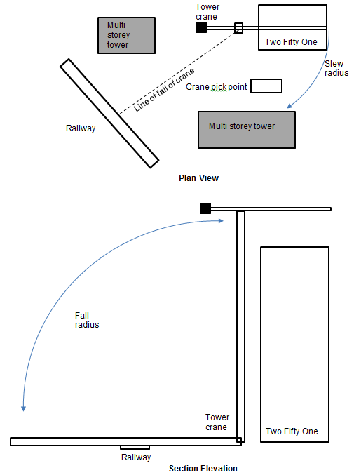
Sketch showing tower crane position in relation to other structures.
Therefore reducing the working load would in fact make the situation worse. The worst load case is therefore an unloaded crane with wind loading. So I’m not so sure a generic application of reduction in loads by 75% makes sense…
Shear Stubs. I beams laid on their side have been used as “shear stubs” to resist shear force applied from the retaining props fixed across the site. The stubs have to have reinforcement bars protruding through them. The holes for the bars were put in the wrong place.
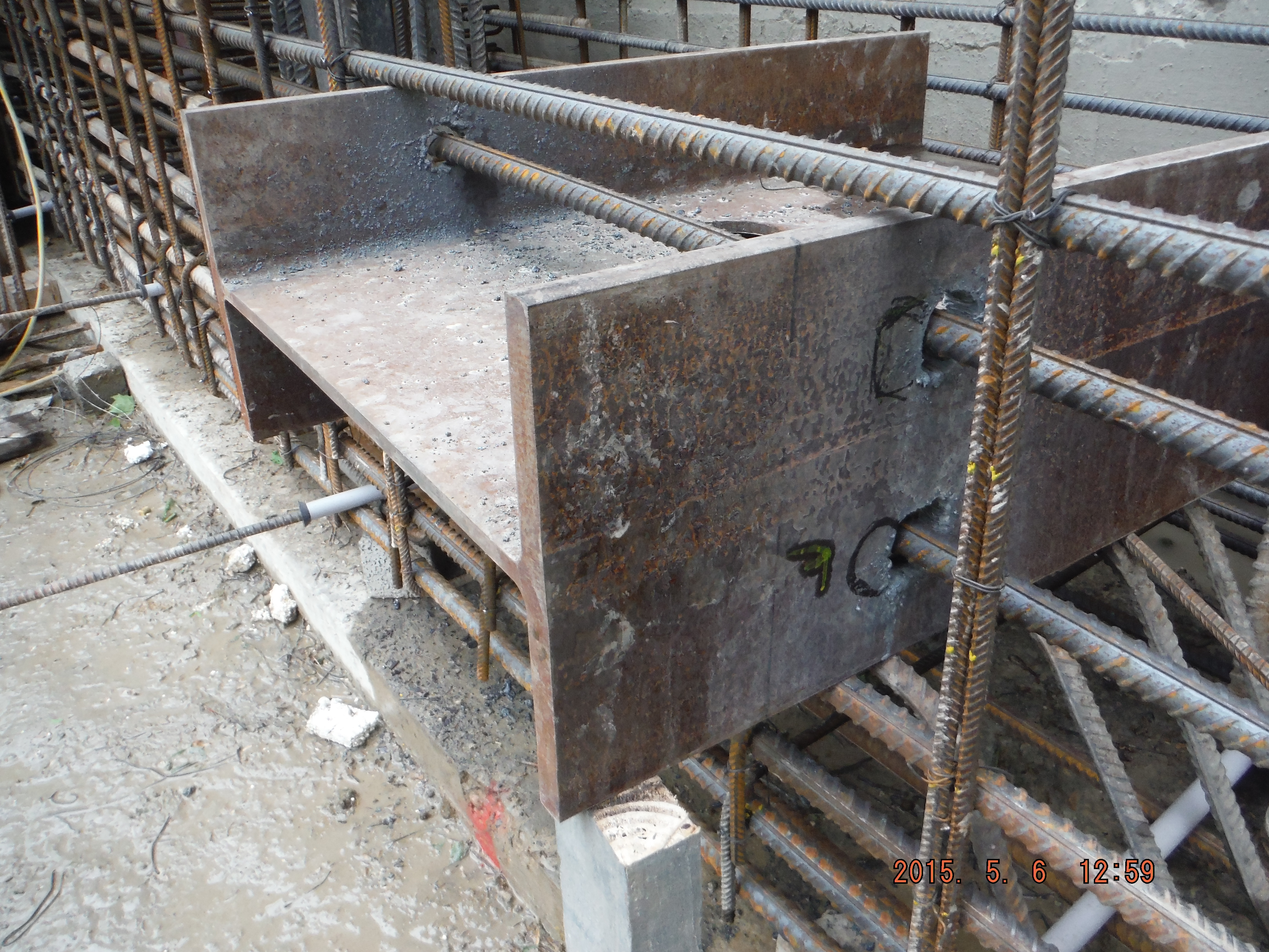
Shear stub, reinforcement holes in the wrong place.
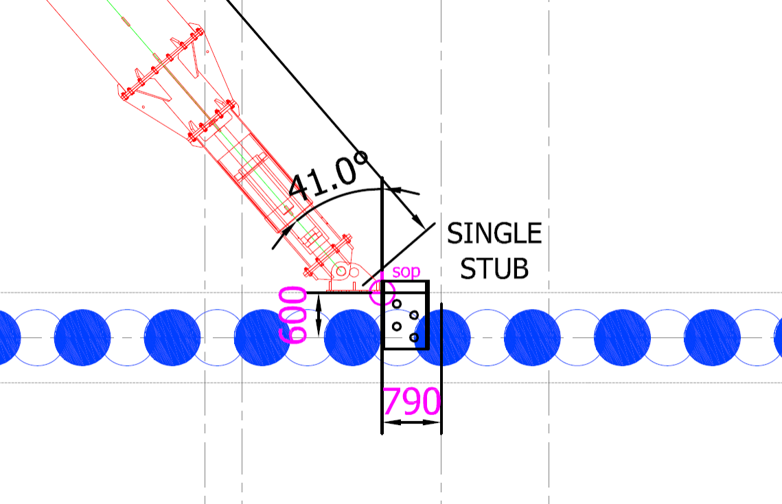
Example of a position of shear stub in relation to prop.
So what? Correcting the problem (increasing the hole size) will result in the flange having a reduced area to be able to resist the force applied.
Action taken? Remove shear stub and have a think.
Thoughts:
- Different stubs have different shear forces applied depending on angle (angle near 90 degrees = less force applied against stub) of the prop (and axial prop load).
- A stub is designed to take a point load of up to 1200kN. The highest prop load is 1140kN giving a 95% utilisation.
- The stub is encased in concrete and therefore it provides resistance against its flange area (625mm x 307mm = 192,000mm squared).
- The area is reduced by 2 x 50mm diameter holes for rebar to pass through (4,000mm squared).
- The incorrect holes reduce the bearing area further by 9000mm squared.
- Based on a total area of 188,000 mm squared the reduction in area is less than the 5% capacity of the worst case situation.
- So the answer – Keep the stub in (too late), reuse stub in any location.
Other thoughts. If the holes were drilled too far towards the near face (i.e. where the prop end plate will act), consideration of the section failure in bending would be important as the section modulus would be reduced, and therefore moment capacity in bending.
You’ll Get What You Pay For
Contract Stuff
Last week I intimated that there was a potential issue pushing a new contract through the procurement process in time before the base contract to which it would be attached expires. At the start of the week we got confirmation that the course of action we pursued was OK with the KOR and I received verification that I could have the funds fairly quickly, which was good. My week then spiralled down into deep, dark, depressing realms of frustration, repeated work and government bureaucracy.
To relate everything I have been required to do will induce eye-stabbing levels of boredom in the reader, and no doubt some level of confusion. I will therefore ‘paraphrase’ and highlight key points.
One of the many hoops I have to jump through along the procurement process is an Independent Government Estimate (IGE) which is essentially a method of making sure that the contractor isn’t ripping us off. This is a fairly important part of being responsible for spending tax dollars on behalf of the taxpayer. Using the Scope of Work I produced I was able to attribute a level of staffing that would be required to fulfill the requirements of the scope and, using pre-negotiated rates from the base contract, attach a cost. In parallel to this I sent a Request for Proposal (RFP) to the Contractor who did the same.
When I received the proposal back from the Contractor I had to wait before I could open it because I still had to get sign off on the IGE; to open the proposal prior to this would be illegal. Office policy dictates that if my IGE and the Contractor Proposal are within 10% of each other I can combine the next stages of the acquisition process into one. Fortunately, when I was able to open the proposal, the bottom lines read within 6% of each other. This meant that I could accept the proposal, no questions asked – as long as I could justify and explain the minor discrepancies in a document called the POM/PNM (this document goes against every JSP101 principle and is judged by weight, not content). On the face of it I could quite easily justify the discrepancies, however when I dug into the weeds I found that the pricing strategies used by myself and the Contractor were wildly different. The overall level of effort was essentially the same, except it was allocated to different task lines. This was a bad thing as it meant that the acquisition would have to go through a negotiation stage, which we don’t have time for. Fortunately, one of the experienced contract officers here recommended that I simply conduct a “scope clarification conference” with the contractor*.
At this juncture it is important to note that negotiating with the contractor without first sending a copy of the Pre-negotiated Objective Memorandum (POM) through the District office is against official policy, however if you call and clarify the scope with him and he sends you an entirely new proposal. Well, that’s fine. Happily the scope was a lot clearer to the Contractor after we had negotiated had our scope clarification conference and I received a second proposal, for a similar amount but broken down in a similar way to the IGE.
Now, the other aspect of this is deciding what pot to pay for the services from. In order to put the scope together I had canvassed opinion around the stakeholders in the various offices as to what level of effort they would require for the period of performance so that I could write a suitable SOW to meet their requirements. However when I called a Purchase Request and Commitment (PR&C) meeting to discuss the issue of paying there was a huge reluctance to stump up the cash! Issues varied from just not having budgeted for what was requested (then I’ll adjust the SOW and you’ll lose your scheduler) to suddenly realising the costs involved are too high to justify. Fortunately for me there was an adult in the room who was able to bat away some of the niff naff poor drills excuses and so the meeting was actually really useful, and there was resolution on who was paying for what…as long as I adjusted the SOW, IGE and POM/PNM…
Lessons –
- The importance of an absolutely watertight scope from the outset, written in consultation with the key stakeholders.
- The importance of lining your funding sources up. Always figure out who is going to pay and then hold them accountable.
- The importance of not leaving anything contractual to the last minute, and then trying to rush task orders through to buy more time to deal with them.
- The sheer amount of interpretation that goes on with regards to rules and policy. This is where the area managers earn their crust and put their head on the block.
Health and Safety Stuff
I echo Henrys sentiments with regards to Health and Safety. I have been on site twice now (not bad in 2 months) and have been assigned some more site based responsibilities. I will retain responsibility for the contract I am setting up, including running it once it’s/ if it gets through, but I am also shortly to be a Project Engineer on 2 projects.
In outline I am working on a site that is home to (currently) three large scale construction projects; all part of the same programme in all but funding; at various stages of construction (from 0 – 30% project completion; 0 – 90% structural completion). I will be working on one that is around 7% complete (out of the ground and having cast in place concrete pours on level 2 presently) and one multi level parking structure that was awarded to the principle contractor around 2 weeks ago. This is due to break ground in c. July.
On my walk around I noticed that the method of access to the second floor slab of one structure was by a wooden ladder, no handrails, which seems to have been erected by a class 2 chippy. There was no method of holding on, other than to hold the rungs, and no tie down at the top or bottom! Good. The edge protection, whilst similar in height to UK spec was also knocked up by the same chippy. There has been a recent revision by the Department of Labor (sic) and Occupational Safety & Health Administration (OSHA) which has placed more stringent measures to site working practices. This might well be a blog in itself.
Chartered Engineer – Professional Engineer Stuff
I have been chatting to the US engineers out here to get a flavour of their ‘route to chartership.’ I won’t go into details for fear of this tome getting even more tomier, but the interesting comparison to draw between the US and UK is that US Professional Engineers (PEs) are pretty much ten a penny out here, compared to the UK, where I gather a Chartered Engineer is rather a rare beast?
And also,
Myself, Danielle, Henry and Jo enjoyed Intercourse immensely. I would highly recommend it to anybody who visits.

Pun intended.

- The sports model.

Health and What?
Over the last week my main achievement has been getting into the USACE computer system and completing my extensive mandatory online training. As Howard and Brad will attest to, this is a significant achievement and through efficiencies the system has managed to ‘trim’ a week from Howard’s time.
In the mean time I have managed a bit of time on site and a few meetings, which have brought home to me the differences in the Health and Safety (H&S) cultures between our Nations. In the UK I would put myself firmly in the category of thinking we have maybe gone a little too far, however out here I am beginning to feel like a H&S fundamentalist. As yet I haven’t reconciled the reasoning, as it is in stark contrast to the incredibly litigious culture out here and so that may have to be a future blog. For now I will give a few examples:
Firstly I was just shocked by this entirely logical solution to working at height: stilts! They appear to be incredibly useful for fitting ceiling grid and both plastering and painting the tops of walls. They give the users freedom and flexibility to work and apparently are quite easy to get the hang of.
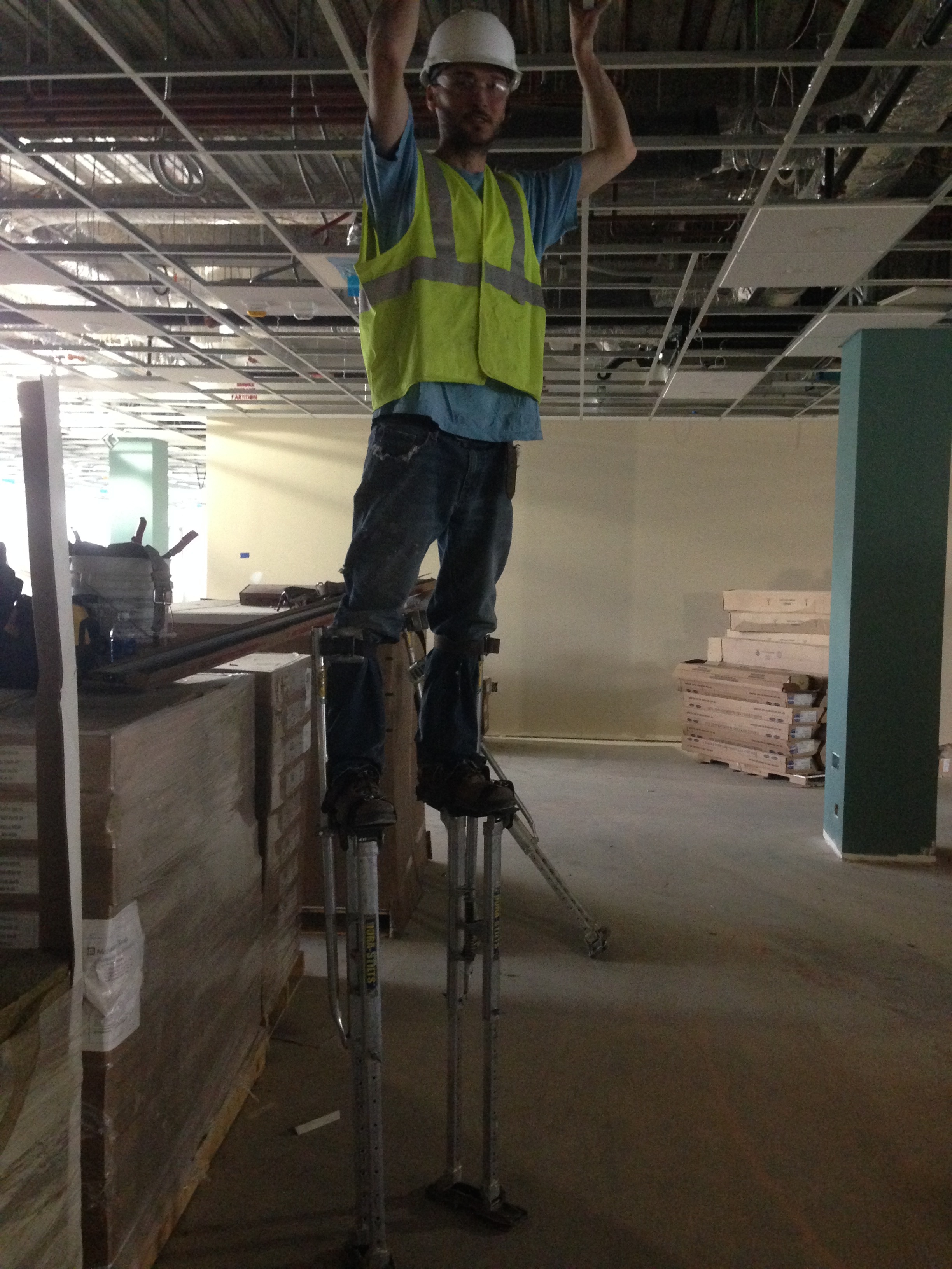
Entirely logical
On the safety front, 6ft is considered working at height and my friend here is about 4ft up. That said there isn’t a specified limit on stilt height in the USACE Health and Safety Manual, just a requirement to protect falls from them of more than 6ft with a guardrail at least 42 inches above stilt height. Therefore the limitation is based on realistic feasibility rather than rules. The USACE H&S Manual stipulates that people must be trained and competent as well as floors being clear of detritus so to me, properly implemented seems an entirely sensible idea.
As the FIG site currently stands
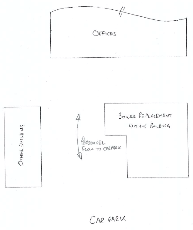
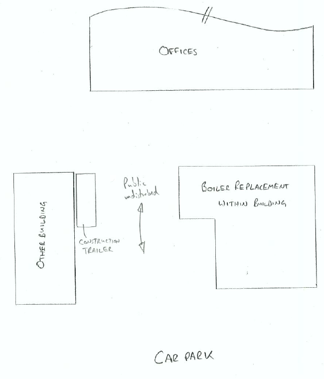
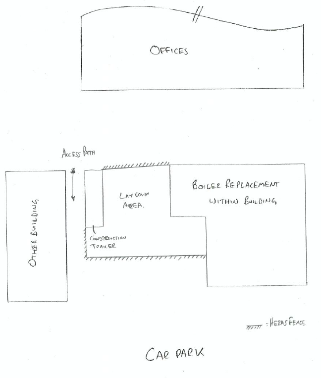
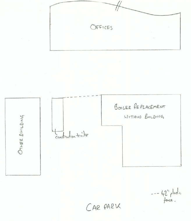
Secondly, it is commonly known that people are simultaneously stupid, curious and lazy. Therefore it makes sense to fence construction sites to shepherd people into areas of safety and away from all the things that mean we require training, site briefings and PPE when we enter a site. Below are 4 very crude layout sketches of the Fort Indiantown Gap (FIG) boiler replacement site showing: the current site, the contractor’s ‘plan’, my plan and the compromised solution.
Their plan
My Plan
The project is quite small and all of the actual engineering will take place inside the building, which is a plant room, so in terms of danger to the public it is not immense. However there will be deliveries, a lay down area and probably some work such as metal cutting done outside of the tight confines of the plant room. As people will, twice a day, walk to and from their cars through the site it seemed sensible to enclose the whole site with a fence to protect people from these dangers and themselves.
On a second level, we appeared to have different ideas of what a fence actually is. My idea of a fence is 8ft high Heras fencing, theirs a 42” high orange barrier fence which is analogous to mine tape at 42”. Whilst I admit it will stop most Americans, including the contractor’s quality manager, to me it still leaves the thought of shortcutting through site open for some people. On a small project like this overheads are clearly tight and there is an obvious cost differential I can understand the reasoning; however the cost of a single litigation event will not only dwarf that but the entire $500,000 contract value. A compromise was achieved and all of my visits will now involve a visual inspection of the fence.
The ‘solution’
Finally, Brad, Danielle, Jo and I took the obligatory visit to Intercourse, primarily to be able to check in on Facebook and with the secondary aim of seeing some Amish people.
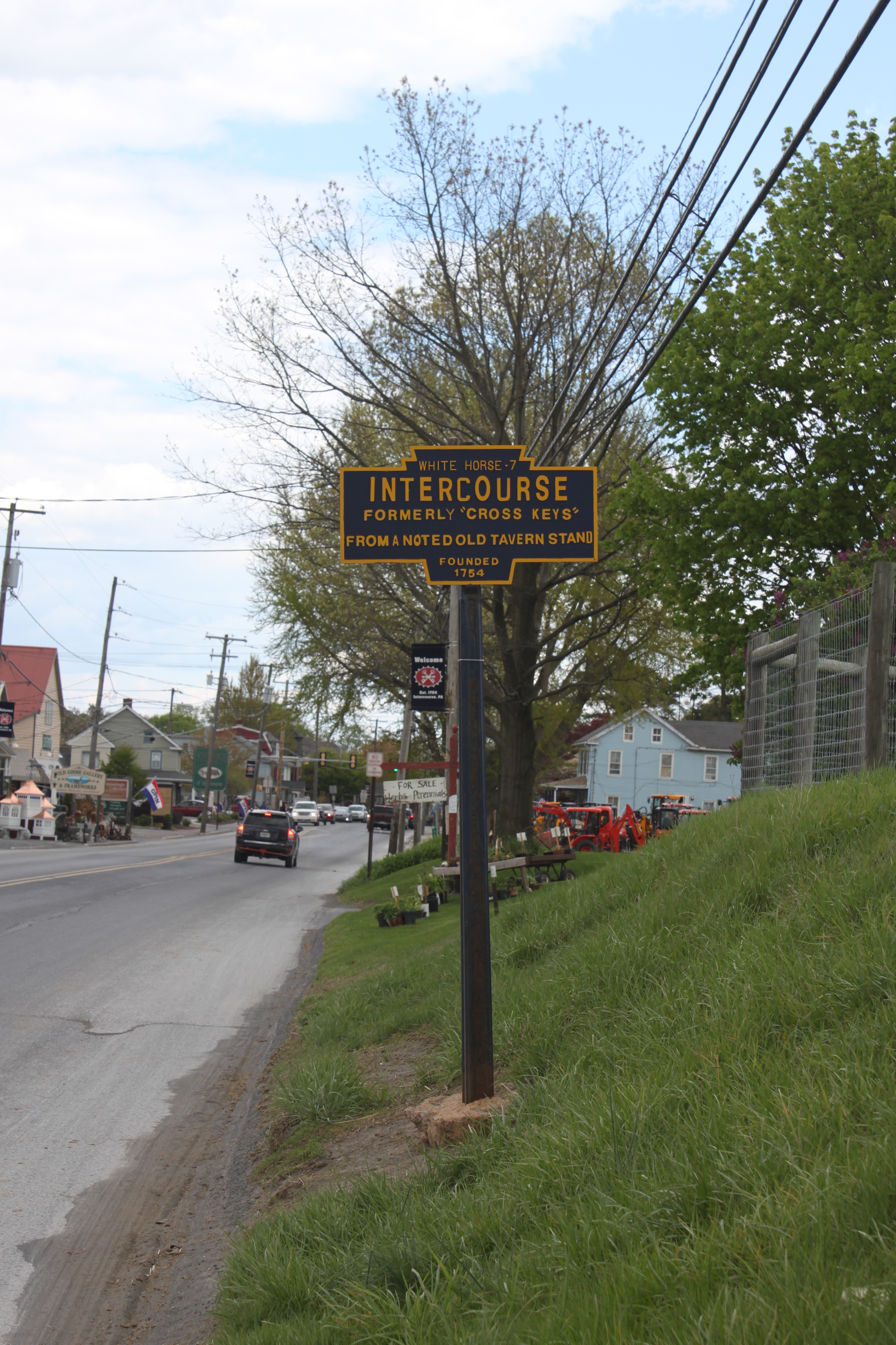
Cue childish sniggering
But, the learning never stops so behold our amazement at house demolition Amish style! It was clearly a big deal as there was quite a crowd, although I was quite disappointed by the looseness of their morals to be using a telehandler that clearly has electrical components, although barely. Apparently it is okay if it is ‘for business’.
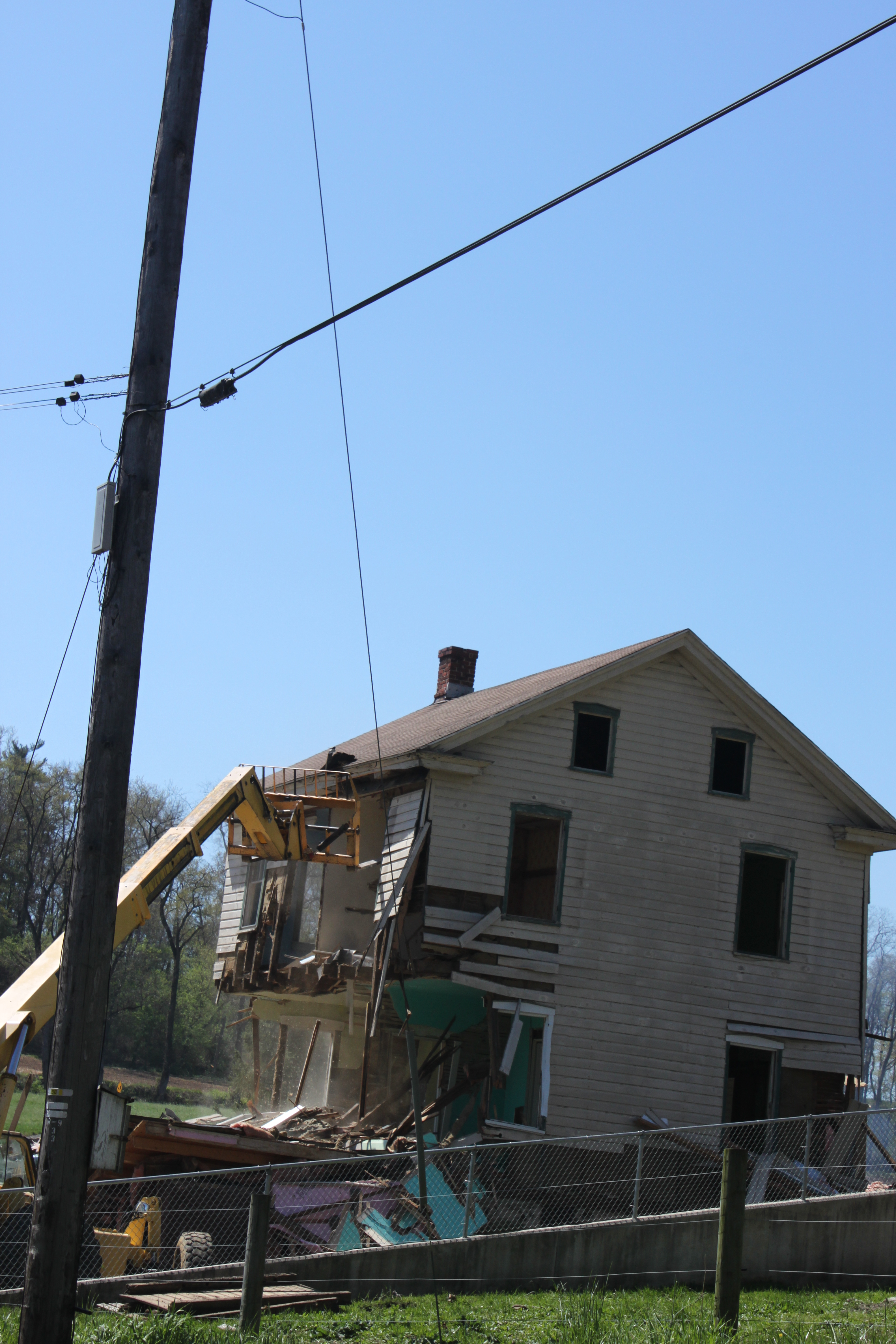
If only I could safely yet quickly take down this house
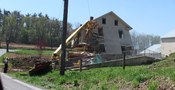
How about?
Looking good
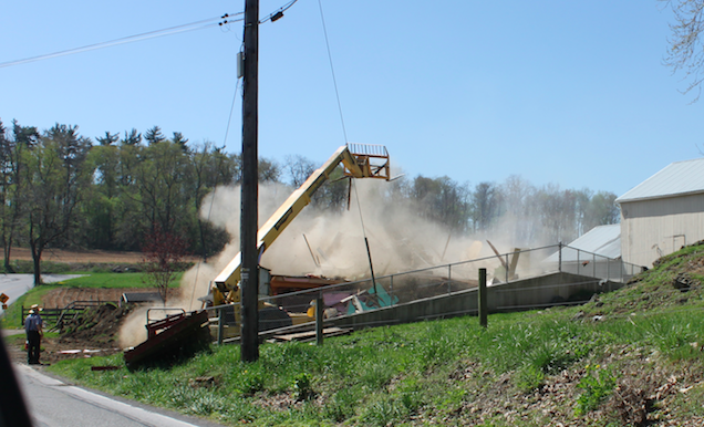
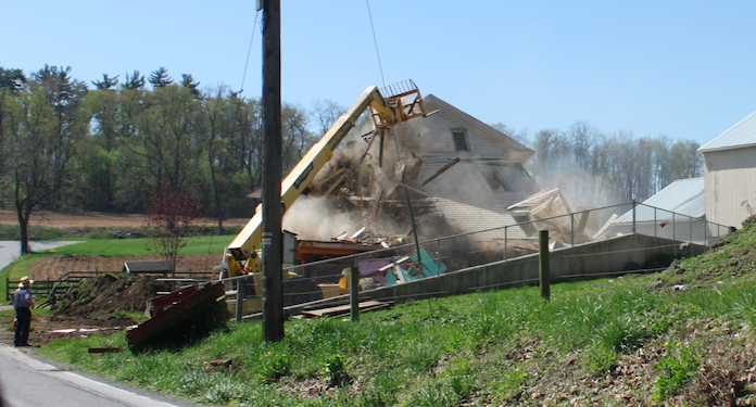
All in a day’s work!
Mañana? I’d be happy with tomorrow…
The excitement and novelty of working in a civilian environment is now starting to wear off and the reality kick in. I used to think terms like “military efficiency” and “planned with military precision” were something of a joke given how inefficient and chaotic Army life can often be. I am now coming to realise that I was pouring scorn on these phrases from the point of view of a person who has only ever worked in a military environment and presumed that the drive to make money in the private sector would ensure things ran smoothly. How wrong I was…
“Ask twice a day, every day for two weeks and it should get done.”
This is actual advice that was given to me by my mentor within the MEP department with regards to getting some work out of the Carillion structural team. All that I need from the structures team is an instruction allow some BWIC holes to be cut through the concrete slab and sheer walls for service to penetrations. The holes were on the original drawing but were either put in the wrong place or missed off when the pour took place, so it shouldn’t take much work for Buro Happold (structural consultant) to approve the holes. Having read Nick’s blog from earlier in the year with regards to civilian’s interpretation of tasks, and from my own experience of working with civilians as a staff officer I was aware that a simple email wouldn’t suffice. A conversation with the appropriate member of the structural team, email and additional conversation later I was confident that the task would proceed. This is when I was given the advice in the quote above. As my mentor predicted a week has passed by and various excuses have been given, the problem passed around the structural team and all attempts to pin down a date for a solution been dodged – for what should be a fairly straight forward task. I am now thoroughly bored and embarrassed with the daily grind of asking the same question (although this appears to be the SOP here) and have decided to take a different tack – apply some military process to the problem. I’ve managed to get the buy in of the structural team to using a simple tracker so that we know what needs to be done and produced a request for work template which specifically details the works needed on one piece of paperwork as opposed to several emails and drawings. Hopefully this will clarify what needs to be done and make the job of approving the work easier for the structural team so that they will turn it around more promptly. We’ll have to wait and see….

Rose wasn’t too impressed when she found out how Carillion do business.
Although the novelty is starting to wear off I am enjoying phase 2. Life in London is great – I’d definitely recommend it as a location for anyone on next years course if there are any jobs available. I’ve got a quarter in the Keep, Kingston-Upon Thames. The quarters aren’t going to win any awards for architecture and certainly don’t blend in with the Victorian town houses, but they are very nice once you’re inside. Richmond park is a 10 minute walk away as is the Thames and it’s possible to be in central London in under an hour on the train. I am currently getting my PT sessions in by cycling to work most days, which at 50 minutes each way is a quicker commute than the the train by about 15 minutes.

One of the stags I regularly pass on my cycle into work.
Oz PCH – Commissioning Jim but not as we know it…
Precommissioning Checks of Water Distribution Commissioning Valves
Who’s who?
Fredon – Mech Infrastructure Subcontractor (work areas includes; plant rooms, services risers and entire basement plant room).
Centigrade – Mech Fit-out Subcontractor (work area includes; floors and corridors).
Why two subcontractors installing the same equipment? Threefold; to reduce the risk attributable to one subcontractor; to reduce the workload to a more manageable % of the overall build; and to ensure one subcontractor wasn’t responsible for too much cost (Fredon’s contract was originally worth approx. AUS$40.7 million but more likely to be AUS$48 million and Centigrade’s originally AUS$27.2 million but more likely AUS$31 million). The important factor is ensuring each clearly understands their working boundaries.
The Issue
In order to commence testing and commissioning of the hot and cold water system, precommissioning checks state that commissioning valves need to be fixed in place in order to measure and balance the flow rates and thus prove the system. On inspection of a number of commissioning valves in a number of plant rooms it was found that they had been installed incorrectly – in some cases there wasn’t sufficient straight line pipe before or after the valve which would skew any readings taken. CIBSE commissioning code and NDY specifications stipulate the valve must be installed at min straight length of 10 x dia upstream and 5 x dia downstream of the valve (as below).

CIBSE Commissioning Code Standard.
However, checking the valve manufacturer, Tour & Andersson’s (TA), data sheet it stipulates the valve must be installed at min straight length of 5 x dia upstream (10 x dia if connected straight to a pump) and 2 x dia downstream of the valve, as shown below.
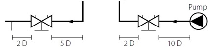
TA Commissioning Standard.
The manufacturer’s data sheets were checked in order to back up our argument (more on that later). Firstly you’ll notice a difference in the downstream length between what CIBSE (5x) and TA (2x) stipulate but you could argue that as the point at which the length is measured from is different, that actually the manufacturer (TA) is approx. 5 x dia when you add the length of the valve itself (approx. 3 x dia). Therefore, only the upstream lengths are different but TA does say 10 x dia if the flow is coming from a pump (essentially creating more turbulence than a bend or change in dia so requiring more length in which to settle back to a more laminar flow) and so worst case is to use 10 x dia upstream and 5 x dia downstream – which is what JHG and NDY stipulate.
In addition not only were the straight line distances incorrect but worse still the pipe line dia was different to the valve dia. In one case there was a 12.5mm dia pipe with a 20mm dia valve fitted in the middle. Below are examples of what was found.
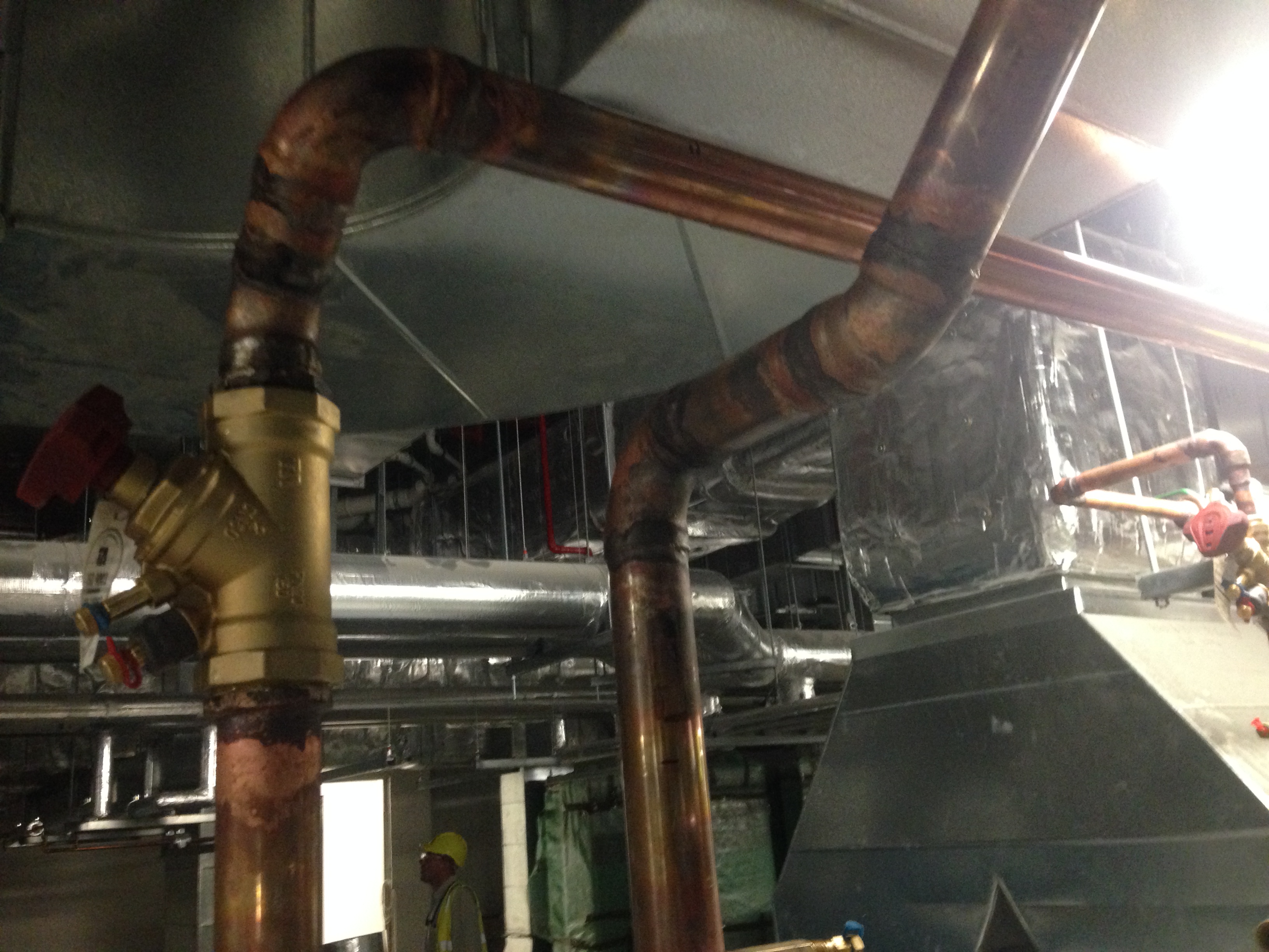
Plant Room 6 Level 4 – flow is south to north. The upstream (south) is within limits (10 x dia) but the downstream (north) should have a straight line pipe section of at least 5 x dia. The valve is 50mm dia = 250mm. Clearly the angle change and then the 90 deg elbow are both inside 250mm so out of limits.

Plant Room 8 Level 2 – flow is right to left. Both upstream (right) and downstream (left) are out of limits. You can see on the right between the lagged fixing and valve that the pipe dia changes from 12.5mm to 20mm. What’s most likely happened here is that they have used the wrong dia valve (pictured is 20mm) for the pipe line of 12.5mm so had to weld in a piece of 20mm pipe to make it fit. Also, just at the edge of the left of the pic the pipe dia changes again – inside the required 5 x dia = 100mm, so out of limits again.
Fredon’s response was that they followed the guidelines as per the Consultant’s Advice Notice (CAN). We pointed out the dims as per CIBSE and TA (the reason we needed to double check TA data sheets) and reiterated that this is what they should be working to not solely the CAN. The CAN is just a notice explaining what work needs to be carried out but must be used in conjunction with documented design data – which they clearly didn’t do.
The Solution
The solution is easy – JHG have rejected the work and rework is required but this time in line with the CIBSE code and NDY Spec.
Commercial Aspects
Fredon will take the hit. There is no recourse as the work is out of scope and has been rejected. A separate notice has been raised to that effect.
Decisions Decisions.
Progress of my contract has been slightly disjointed by the activities of last week, which was great exposure to the wider work that the USACE undertakes. Timing for this contract proposal is not a little tight and therefore I had to ensure that the proposal was with the contractor before I left last week so that concurrent activity could take place (me, on a jolly, him pricing up the proposal).
Whilst I was away the contractor who I am trying to set up the new contract with had a look through my Scope of Work and had got back to me with a few RFIs. Normally this wouldn’t be a problem, but the Contracting Officer’s Representative (KOR…yes, with a K…) was away on leave until midweek and has such a tight rein that decisions became almost impossible.
The crux of the issue was that I had been asked to develop such a broad scope that there was overlap between an existing contract, which expires shortly but might be extended, and mine. Understandably, with hindsight, this confused the contractor somewhat who wanted to know if there was an entirely new requirement, which would mean restructuring his organisation or even hiring new personnel in order to source additional manpower, or if this new contract would effectively supersede the old one. Fair point, well presented.
Now, my supervisor and I both knew that it wasn’t the former; therefore it must be the latter. However exactly HOW the KOR wanted to skin this was what my supervisor was worried about; should we supersede the old contract and replace it with a new one (which encompasses everything on the old contract anyway) or re-submit the Statement of Works (SoW) removing the overlaps and have 2 contracts? The contractor didn’t mind either way, but for a while there was a real prospect of having to wait until the KOR returned before making a decision.
What I proposed is, that given we seem fairly content on the KORs intent*, we price up my new Statement of Work in its own right (ie to supersede the old contract) and give a brief to the KOR upon her arrival back to work about what we had done. (Begging forgiveness in my supervisors eyes – sort of mission command in mine) I re-sent the amended Statement of Work to the contractor with a covering e-mail which highlighted our position and followed up with a telephone call highlighting in quite open detail what we were trying to achieve. He seemed like a fairly good bloke who understood and was grateful that things were progressing. The contract seems to be worth giving the stupid brit some latitude for error in any case. (Incidentally he sent me his RFIs and CC’d in the entire world, and their dogs, so my error was in fairly stark contrast!)
On a plus note I submitted the reservation for the $1.8m in good time and am just waiting for the nod that I can have it. On a super plus note I now have another ID card. This one gets me onto site, no questions asked, no escort required. Win! Those who read my last blog should see the implied ‘thing’ here…Foreign or not, I must be a good egg!
On top of this I chaired another meeting between project managers and schedulers and our scheduling contractor in a continued attempt to get the Integrated Master Schedule back up and running. Last weeks meeting was fairly fruitless because the contractor hadn’t actually managed to input all of the task lines. This made drawing logic ties between them particularly tricky. What it did allow me to do though was to identify key players who actually had useful things to contribute, and who was there for their own agenda. The distribution for this weeks meeting was significantly cut.
And also

We hosted a tacky soiree on our estate, complete with Union Jack, BBQ, Bratwurst and red plastic cups; a real melting pot of cultural ideas. There was beer aplenty and burnt sausages were being heartily gobbled (not a euphemism) but at around 1430 when I returned from a pressing engagement elsewhere I found my wife, ably assisted by Henrys wife, handing out cups of Tetley tea, (British blend)… much to the confusion of the American contingent. They still don’t understand 1000hrs T&T either. ..yet.
Truck MPG; Confirmed bad. 18Mpg.
*and because it was less work to reach the some outcome…
Site Two Fifty One – Concrete
Site Two Fifty One – Concrete
This week the concrete pour for the first section of capping beam was completed. After the discussions on my last blog, the pour size was reduced to 16.6m (from 40m).
Formwork. The shuttering worked which was pleasing because we had brought the pour forward a day due to a lack of concrete availability on a Friday before a long weekend and so it was somewhat manic to get things ready in time. It did mean the grout check line was being installed while the concreting started!
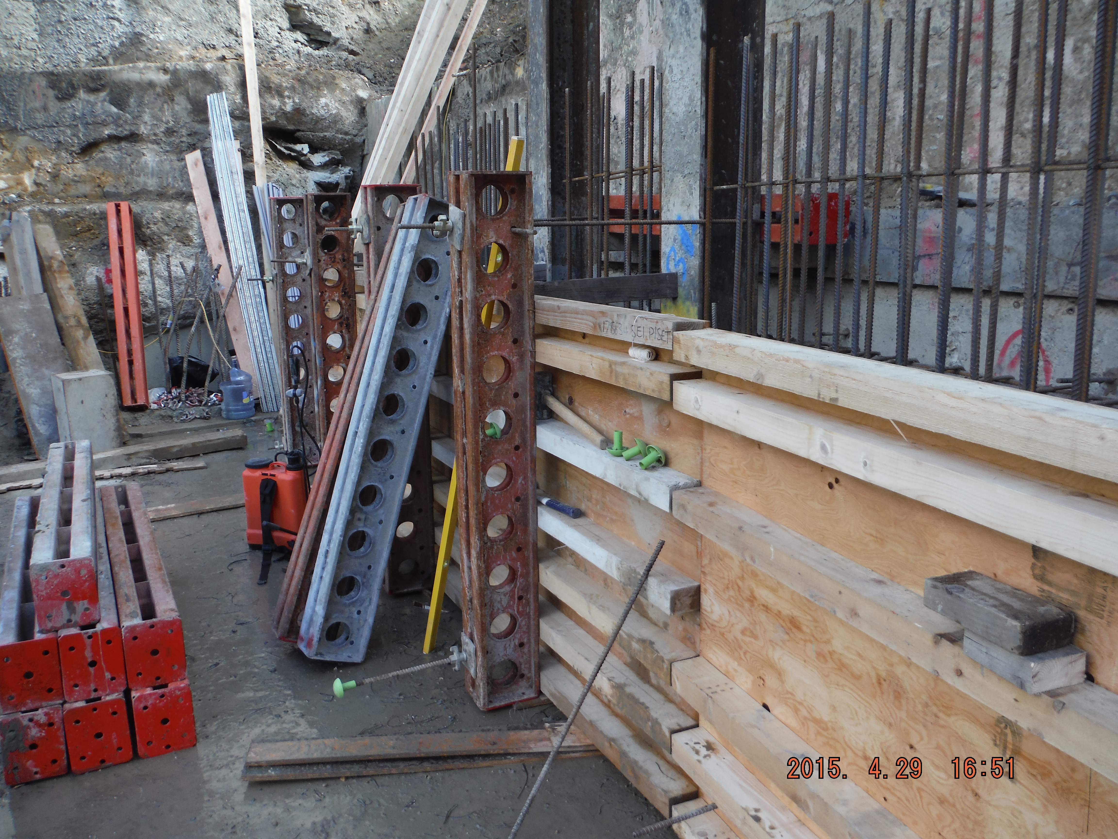
Formwork construction. Waler beams only 100mm deep, therefore smaller spacing at bottom to remain within moment capacity of the section. Soldiers at 1.2m spacing to align with male pile reinforcement which the dywidag ties from.
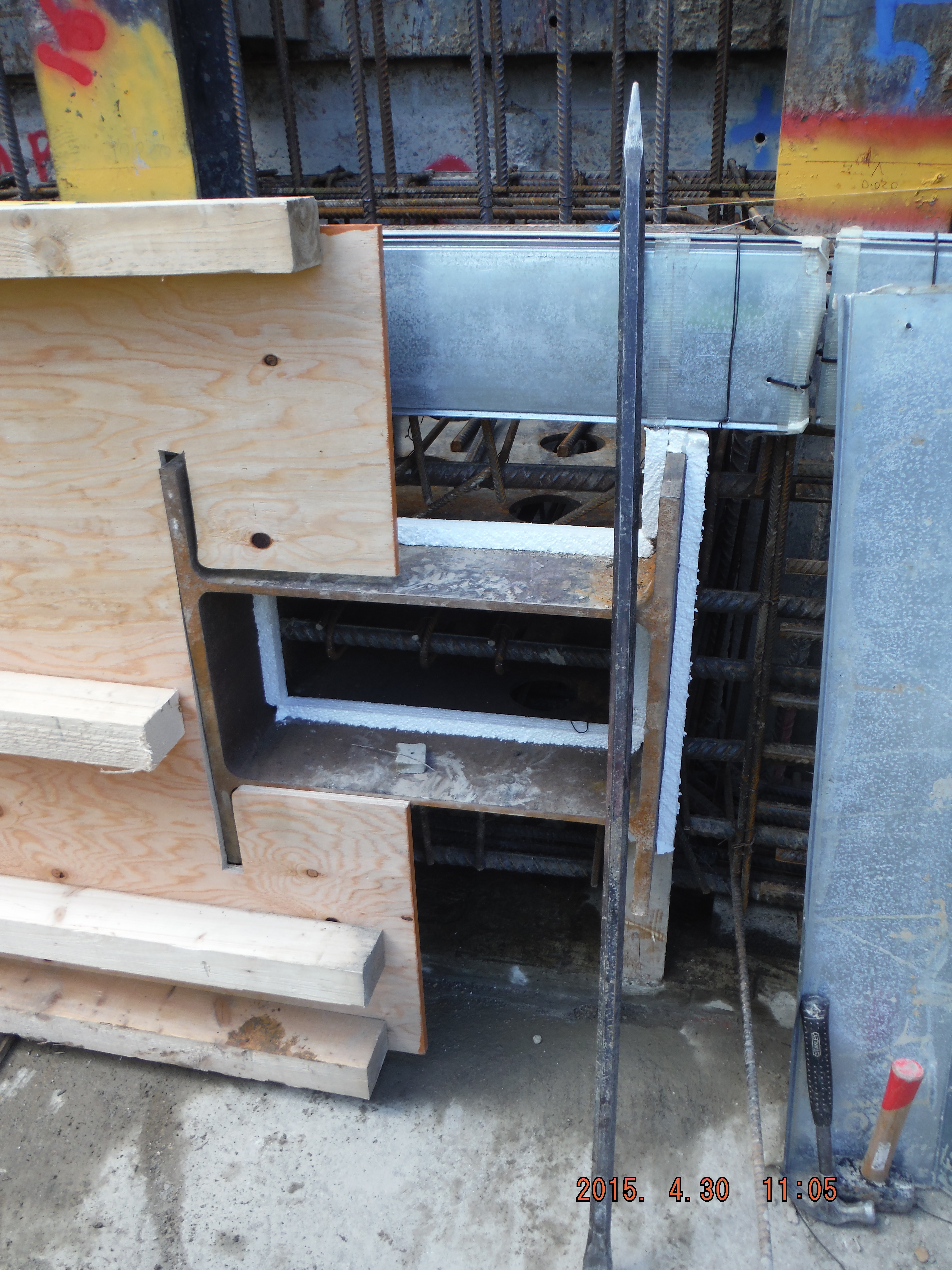
Polystyrene used as a 25mm rebate to enable the shear stubs to be burnt off after use and the concrete made good.
Pete – use of hirib below in a stop end. The expanded metal helps form a rough edge to make a joint for the next pour. This only works for Level 1 waterproof sections (see below).
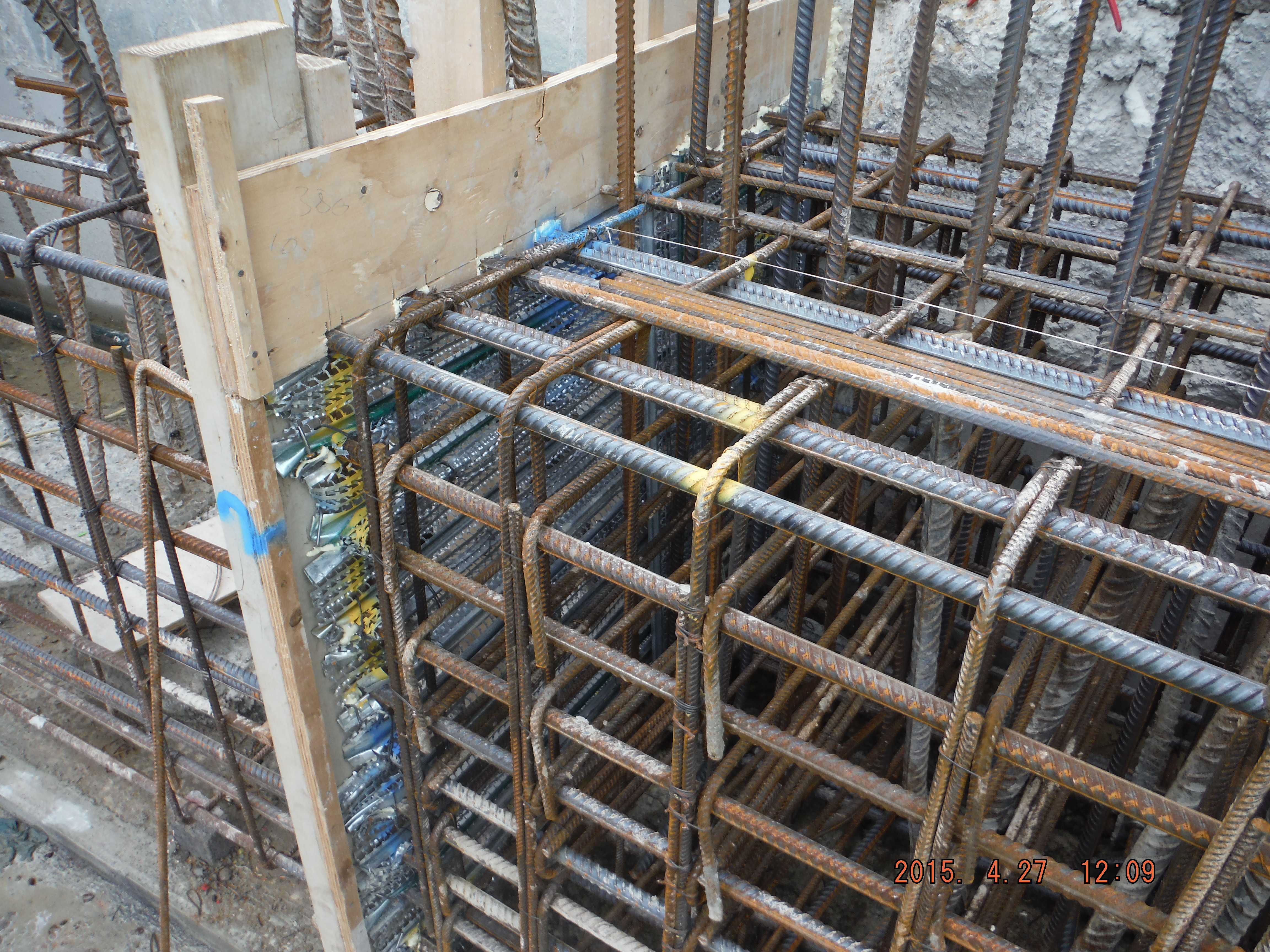
Hirib stop end – mechanical means to form a cold construction joint eliminating the requirement for scabbling.
Delivery method. The method of delivery was via a rolling skip with tremie pipe and crane. This was used because 1. The crane was available, 2. There was no space to get a concrete wagon or excavator near to the beam.
Pumping was also considered but would be very expensive for a small pour (circa £12k for 1 day hire).
Delivery by skip actually meant the pour was very controlled (reduced pressures on formwork) and safe for the operatives doing the concreting because of its controllability.
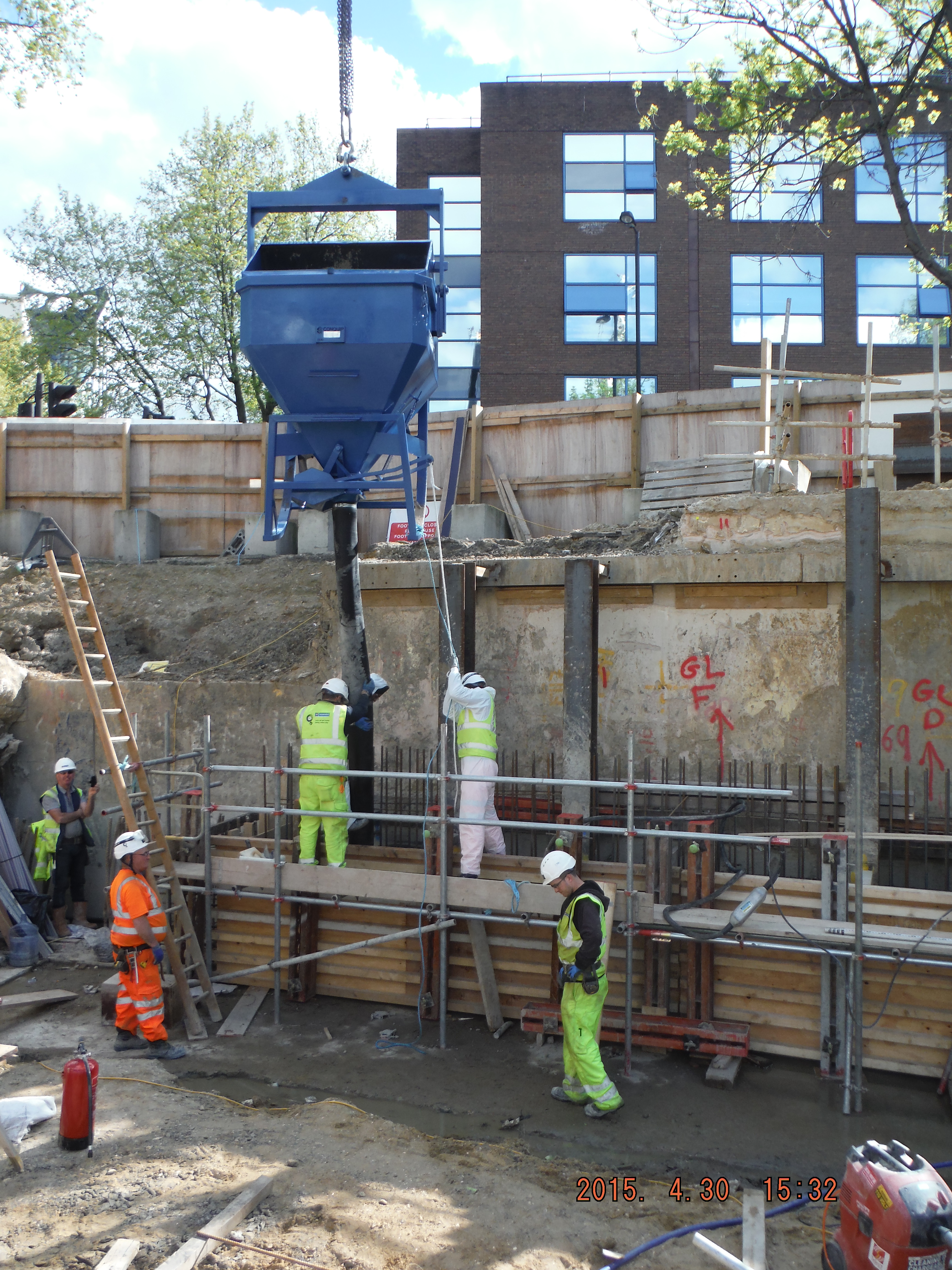
Concrete delivery by skip with 3m tremie pipe.

Rolling skip means it is easy to discharge into from the concrete wagon.
Curing. The top of the capping beam is going to have a retaining wall constructed on top of it, hence the starter bars. The inner side of the capping beam will form the start of the basement slab. Therefore half of beam needed to be retarded, half cured. The point of the retardant was to reduce the speed of curing to allow the beam to be jet-washed the following day in order to roughen the surface to make better interlock for the future wall pour.
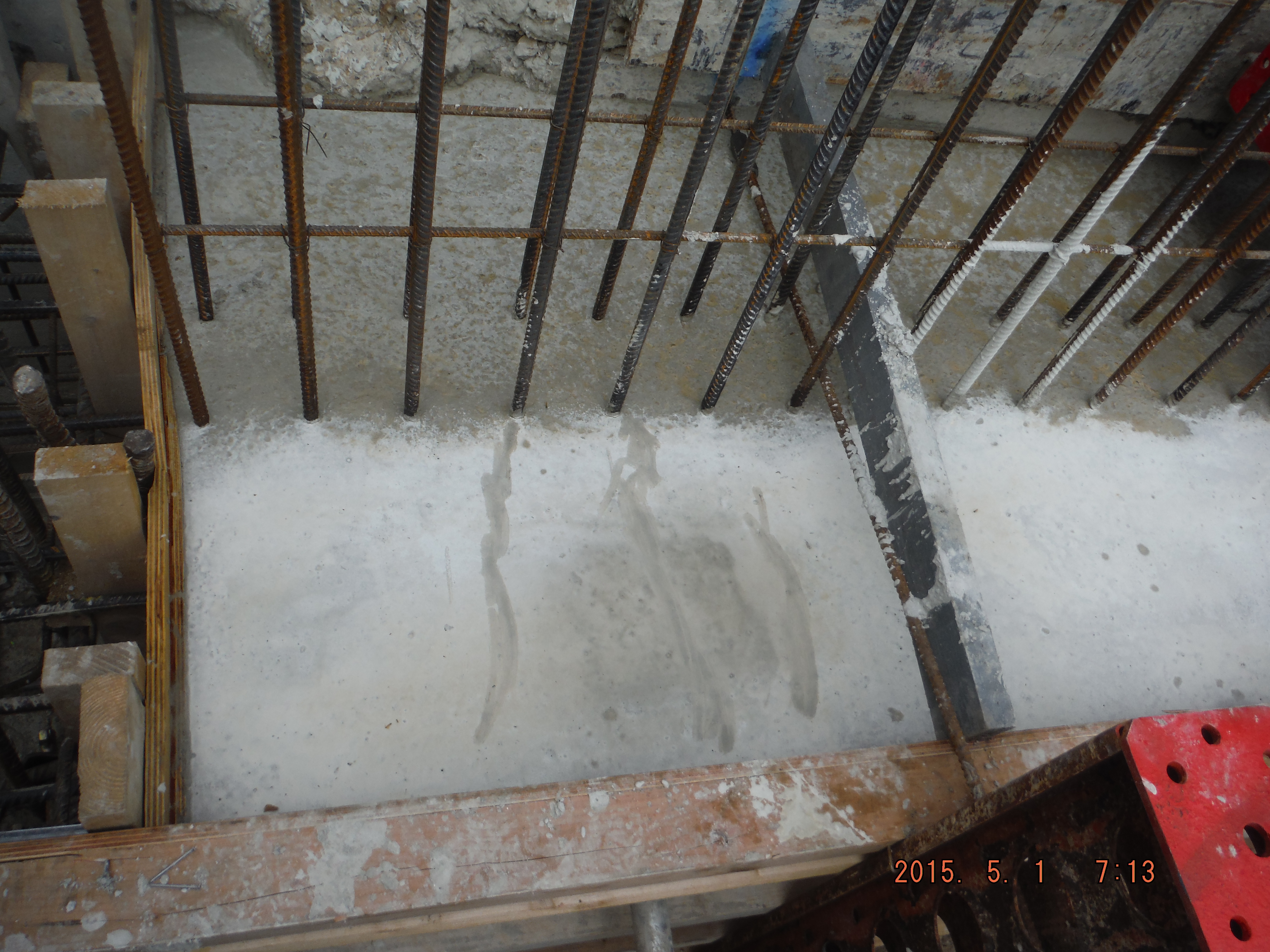
Near surface – cured for part of future basement level 1 slab. Far surface retarded for future retaining wall.
Cracks. The concrete mix and steel design is meant to help reduce cracking (maximum crack width allowable: 0.2mm), although only very limited trials have been done on this so it will be interesting to see what we get. The waterproofing requirement of the beam varies between level 1 (beading of water allowed on inside) to level 3 (completely waterproof). However crack width is limited to 0.2mm for the whole perimeter. The only difference is the level 3 sections are going to have a hydrophilic strip (between piles and bottom of capping beam) and an “Adprufe” additive in the concrete mix to make the beam waterproof.
It is likely non-structural cracks will form (which cause durability issues because of reinforcement corrosion) within a day of the pour. The cover has been set at 55mm which means the as cracks reduce in width with depth, the reinforcement should be protected. Applying curing agent to the beam aims to protect it from rapid drying out of the concrete and therefore reduce cracking. Before hardening of the concrete plastic cracks may well form due to either plastic shrinkage or plastic settlement. It looks as though plastic settlement around the reinforcement due to “bleeding” (water rising to the beam surface shortly after compaction due to heavier mix constituents moving down due to gravity) has already occurred, although very minor at this stage.
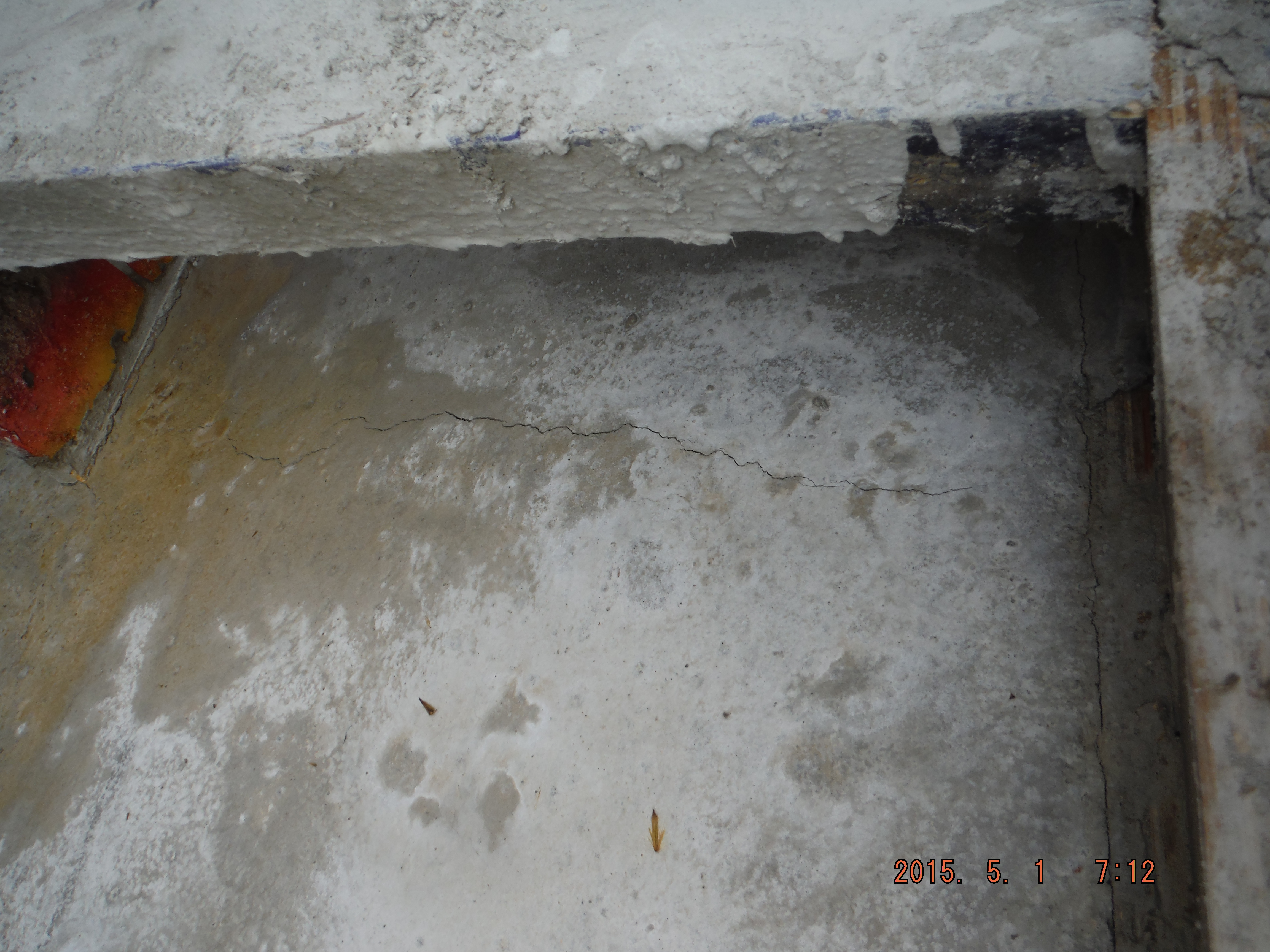
Plastic settlement crack forming over link reinforcement.
Time will tell regarding the growth or healing of the cracks and so I will monitor the situation after the bank holiday.
It is now a case of: underpin, break piles, reinforcement, formwork, concrete and repeat…
