Oz PCH – Knock-on Effect Issues
Diagnostic Imaging Unit (DIU)
I’m going to discuss an issue (small relative to the majority seen) but one that highlights a good example of the knock-on effects of last-min (late) design change.
The DIU houses the imaging equipment found in most modern hospitals the biggest pieces being the Magnetic Resonance Imaging (MRI) scanner. Here there is one to be installed with a further two areas completely fitted out (inc all control equipment etc) to be installed for future use. One of these future pieces is to be a Position Emission Tomography (PET) MRI scanner. PET is used when searching for cancerous tumours predominantly in the head, brain, neck and prostate and gives clinicians vital info like metabolism or physiology of the tumour. So, when coupled with MRI (used for soft tissue imaging like a CT scan would but with the added benefit of not exposing the patient to ionising radiation – important in paediatric oncology) it allows a key advantage over pure PET alone as PET is not capable of accurately assessing the local extent of the primary tissue in certain locations of the body like the head and neck, whereas MRI can (HealthPACT, 2012).
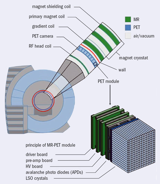
Scanner Construction.
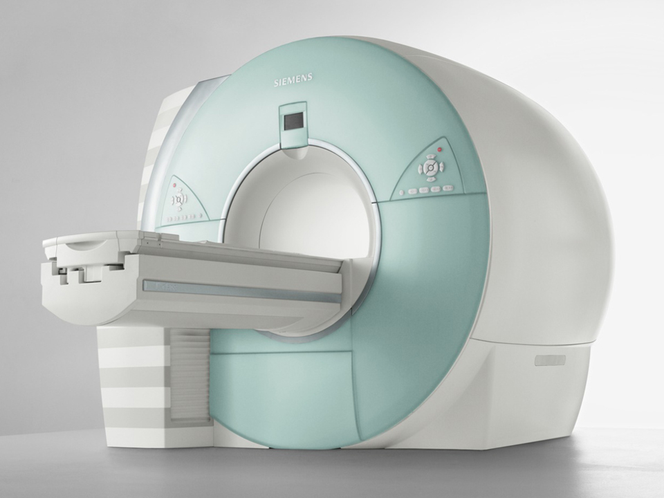
Siemens PET – MRI Scanner.
Architectural Design Issue
The DIU was originally designed (by the Architects BCJH) to be located on the ground floor but…and I can only presume due to lack of stakeholder engagement even though BCJH are an amalgamation of specialist hospital design architects so should know better, that particular area was right above the upper basesment car park as the red dotted rectangle (PET MRI room) depicts below when comparing both ground and upper basement floors. The blue dotted rectangle being the new location sufficient distance from the car parking spaces below.
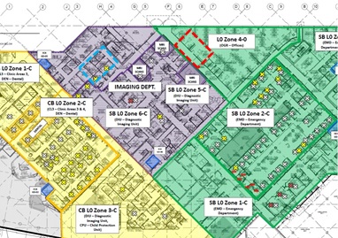
Ground Floor – DIU dept shaded purple.
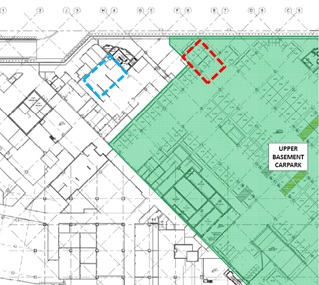
Upper Basement – Carpark in shaded green.
The issue is that each MRI room emits a large electric field as a result of the MRI technology using super strength magnets. Due to the design of the magnets, being symmetrical, the electric charge produced, found using Gauss’ Law as the below pic shows, creates some very serious problems. In simplistic terms the electric field is so great that there are limits to the proximity of moving (dynamic) metal objects in order for the scanner to work correctly and not have the metal objects causing discrepancies in the scan results. So you can imagine the surprise when the clinical technicians (stakeholders) found out about a carpark full of potentially huge dynamic metal objects right beneath their scanners. The Gauss Field seen in the pic below isn’t of the PET MRI room but of another MRI room for illustration purposes – the 0.5 mT (red field line) is the one that can affect humans and metal objects (like people walking past with a pacemaker fitted) and so is the one that must be contained in the Faraday cage. As a rough comparison your standard vacuum cleaner (generally emitting the highest magnetic field strength of any appliance found in the household) gives out 0.13 – 2 µT at a distance of 1m away vs a MRI scanner giving out 10 – 20 mT at 1m away. The MRI scanner being x 103 (1,000 times) higher but the exposure time of the MRI scanner is seconds versus minutes when operating a vacuum cleaner.
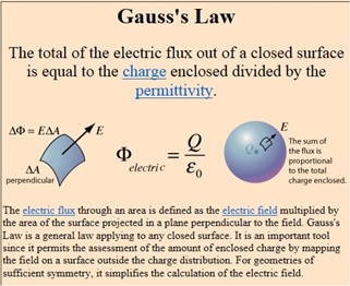
Gauss’ Law.
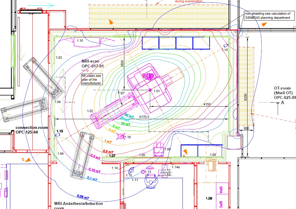
Gauss Field of MRI Scanner.
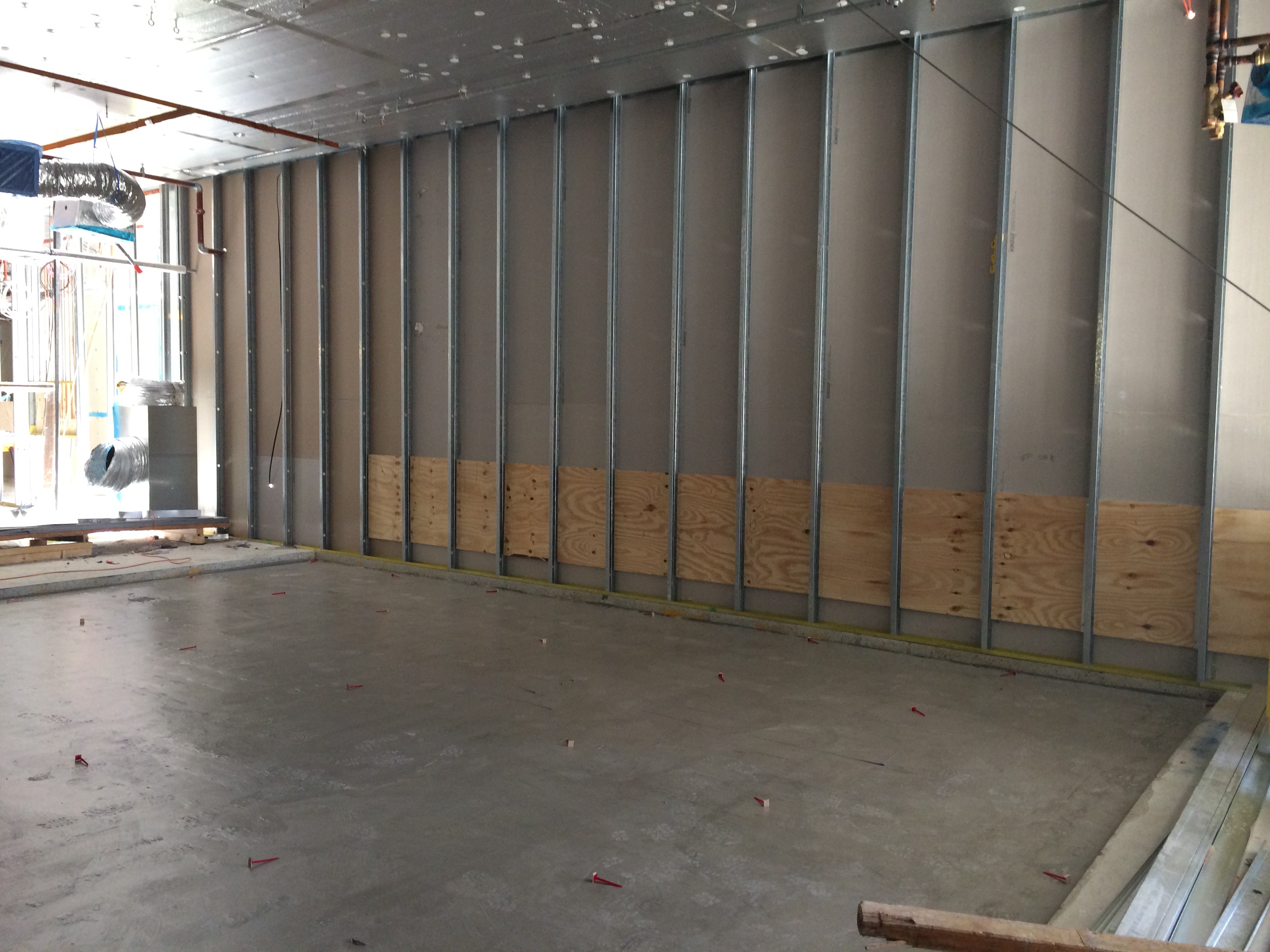
To reduce the effects of the Gauss field a faraday cage is constructed made of copper sheeting that is attached to the inside of the room via wooden battens and acts as a ‘force field’ surrounding the MRI scanner (charged particle) by basically conducting the charge thus stopping it spreading any further. However, the charge creates high levels of electromagnetic radiation which are potentially harmful and so a skin of silicon steel sheeting is attached to the outer side of the wooden battens in order to stop it. This construction is the same all the way around the scanner with the only slight difference being how it is placed into the floor. The pic below shows the set-down (72mm cut-out) in the concrete slab where the 6mm silicon steel sheets are placed followed by 19mm particleboard acting as a divider before the copper sheeting is added. Finally a 16mm particleboard, a 12mm particleboard and a 3mm vinyl sheet flooring are added coming up flush to avoid any raised edges in the finished floor (required for trolley wheels and eliminating as a trip hazard).
PET- MRI Room showing Set-down in the concrete slab.
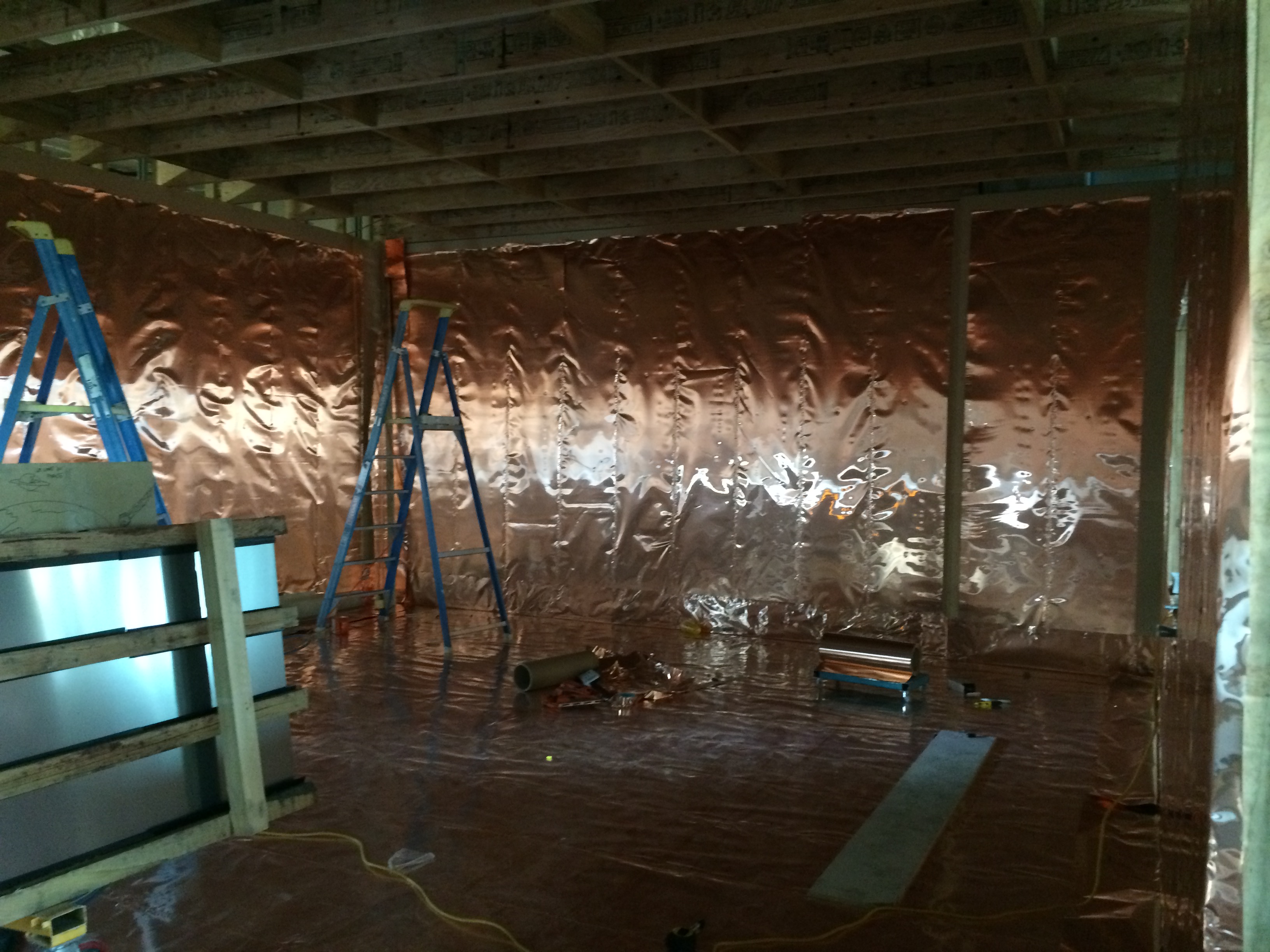
MRI Room showing the Copper Faraday Cage.
MRI Room showing the Silicon Steel Sheeting from the outside.
So although the faraday cage should stop the electric field getting out there are still obviously key technical design reasons why you don’t want it sat on top of tens of tonnes of metal cars moving around causing dynamic interference. This could be a good technical TMR topic, something like ‘what technical considerations should be investigated in the design and construction of a MRI room in a hospital and what design provides the best protection’?
Solution
A very expensive complete department move. Due to the functional interoperability of the department you couldn’t just relocate the MRI rooms per se but the entire department. The DIU is still on the same floor but now moved away from any potential dynamic mass of metal. Contractually JHG have put in a claim to the architects as moving the whole department has/will cost $ hundreds of thousands.
Knock-on Effects
Apart from having to redesign the layout of that particular area of the floor, including the requirement to fill what was going to be a source of natural light through an architecturally pretty glass roof will concrete, other building services issues arose.
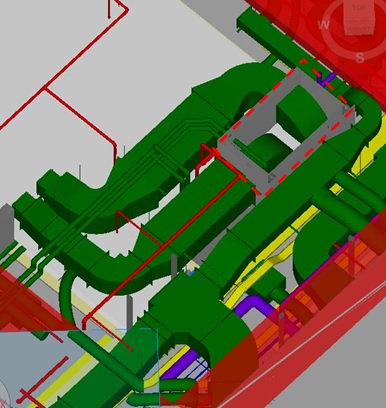
The BIM federated model below shows part of the PET MRI room. The orange rectangle is where a partition wall is yet to go up that divides the scanner room to the left and the electronics room (red dotted rectangle) to the right. In here the larger green box in the enclosed walls houses a Fan Coil Unit (FCU) for that floor area, the smaller green box is the dedicated cooling unit for that electronics room and the red piping/blob (barometric damper) is the pre-action fire suppression sprinkler system which had to change from a normal automatic wet sprinkler system so as to avoid potential water damage to the PET MRI scanner (approx. $2 million) meaning the barometric damper could not be put in the actual room due to the faraday cage.
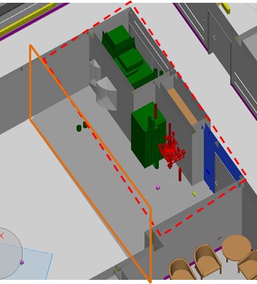
BIM Federated Model of PET – MRI Room and Electronics Room.
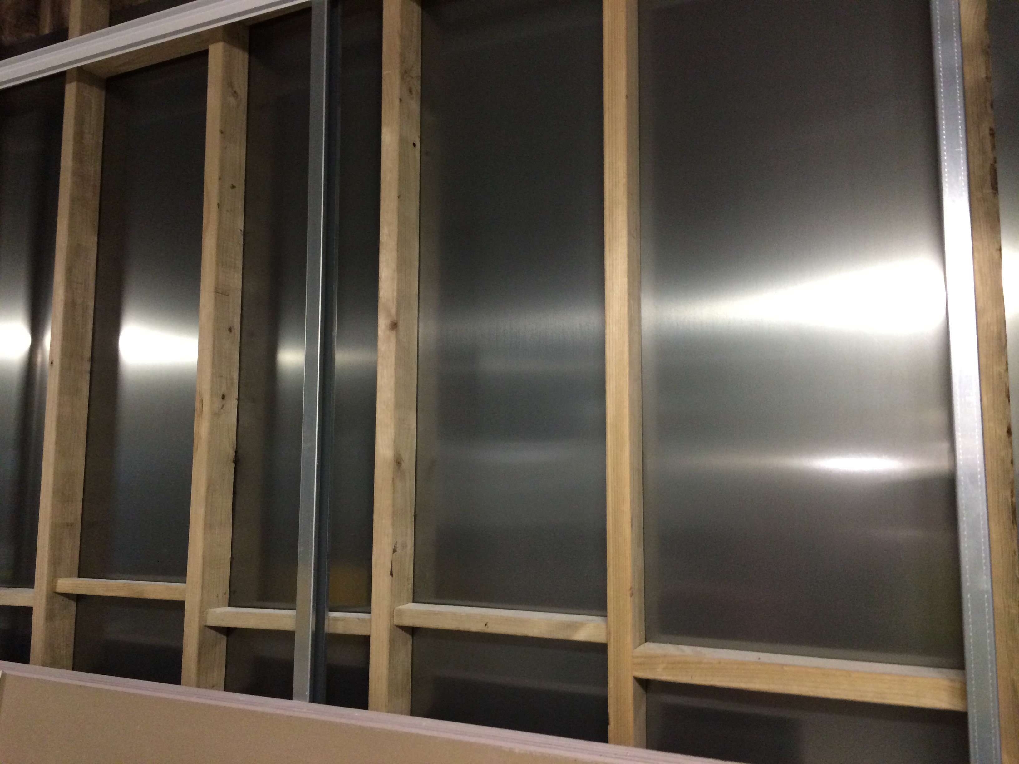
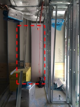
The on-site photo below (taken from the edge of the partition wall) shows the internal framework of the surrounding walls – you can make out the FCU compartment (dotted red line) and the ductwork, insulated supply (blue arrow) and extract (red arrow).
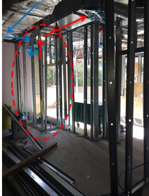
Electronics Room showing FCU location and ductwork.
The issue is that Siemens need to install their electronic equipment in this room (including the electrical safety working zones required) and are fighting for space even using the partition wall (orange rectangle). What’s making the situation worse is that FCU has been installed 180 degrees round the wrong way making the inspection/maintenance access doors completely redundant and requiring extra door panels on the inside of the room as seen by the grey arcs depicting the swing radius of the two inspection/maint panels in the BIM model above. Below shows the original FCU access doors and the main room door which is now planned to be outward opening (into the corridor) and moved round the corner.
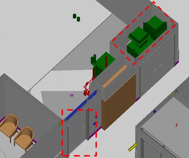
Electronics Room – Corridor View with current door location.
The proposed new door location, shown below (red dotted line not to scale) will just fit at 1m in width.
Proposed new door location.
The obvious solution would be to turn the FCU round by 180 degrees so the inspection/maint panels marry up with the access doors however as shown in the model below and first photo the supply and return ductwork is already installed and there is no space or desire to change as this would be costly. Siemens have now been tasked to detail exactly what wall space they require for their equipment in order to resolve the issue.
BIM Model of Ductwork in ceiling space.
The below annotated dwg is the proposed solution for Siemens and we are awaiting their final decision. Note the faraday cage (dashed green line around the perimeter of the scanner room) and in the electronics room the green boxes are the location of equipment with the orange boxes being the safe working zones so you can see how tight it is. Also, the shaded green boxes are the space gained by relocating the door round the corner so Siemens should be satisfied.
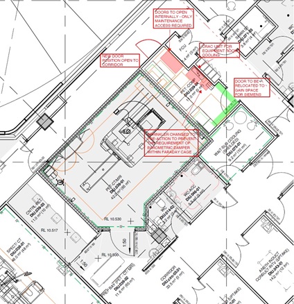
Shop Drawing of relocated electronics room access door and FCU maint doors.

Thanks Fran,
Never heard of Grain Oriented Electrical Steel before so I’ve learnt two new things today already! I have to wonder if it might not have been more cost effective to lose a couple of parking bays and us that space as storage, which will always sneak into parking areas anyway?
Richard,
Absolutely it would have been much more cost effective to do away with those parking spaces in the affected area but these particular spaces were for delivery/waste disposal vehicles and so couldn’t and wouldn’t be negotiated.
Thanks for the update. Suprised it was not simpler to relocate delivery & waste than an entire department with MRI scanners and the need for recessed floor slabs etc? I suspect a didactic decision with too little reflection in action….
Richard,
I have a little more detail on why the complete department move went ahead opposed to simply scrapping a few parking bays.
1. The parking bays are actually leased out by the State for revenue purposes and JHG didn’t want to get commercially involved with lifecycle cost issues.
2. It wasn’t just the parking bays on the floor below that were in proximity of the MRI machine. There was also an adjacent corridor on the same floor which was designated for transiting of patients in their beds and for large trolleys. JHG identified the potential risk for interference caused to patient’s scans as too great which could possibly lead to litigation.
3. Finally, JHG were putting in a claim against the architects BCJH for the entire cost as it was their poor design that caused the move. This also means any associated costs as a result of the move would also be added to the claim. Therefore, hopefully in the end JHG shouldn’t bear any of the cost.
Thanks Fran,
That makes more sense of it now, particularly the final point. Essentially JHG were of the view that they were at nil risk from cost issues and to modify a design slightly and not achieve total quality carried greater risk than time (attributable to others errors) and cost.
This will be intersting to watch play out. A sharp lawyer for the architect might suggest that JHG deliberately incurred costs for the project by failing to manage the risk on a project basis as a competent MC should and instead opted to try to minimise their risk at cost to others i.e. they are trying to make the architects pay for their commercial risk limiting strategy.
There is an interesting discussion at review on risk in this piece!
Fran, nice post. I had no idea how powerful the MRI scanners were, although the clue should have been that the ones I have seen have always been buried in basements. With regard to the TMR topic, I would probably think about analysing the communication factors that affect complex projects like this, taking careful consideration of the affects of the time available for decision making and the contractual relationships. Sort of a precis of a construction industry version of the Psychology of Military Incompetence.