Oz PCH – Pipe sizing issues leading to serious commercial implications…
Back in Oct 14 correspondence from NDY (Design Consultants) to Fredon (Mech Installation Subcontractor) raised an issue and posed an RFI regarding both Hot & Chilled water schematics. The RFI asked confirmation that all pipework had been sized and the network designed in accordance with a maximum velocity of 2.5 m/s and maximum pressure loss of 400 Pa/m. Fredon’s reply was yes it had.
In Jan 15 a meeting was held between JHG, NDY and Fredon which highlighted some issues with pipe sizing as referred to above.
In Feb 15, JHG with Cundall (commissioning consultants) conducted a review of all pipework sizing across the project. They found a number of incorrectly sized pipe sections which, although were within the acceptable velocity limits resulted in pressure losses exceeding the maximum 400 Pa/m. These were marked up and sent to Fredon to address asking that they carry out a review to ensure the issues were resolved as soon as possible. In addition it was determined there were also a number of commissioning stations missing (also marked up on dwgs) thus potentially jeopardising the ability to correctly commission the system in accordance with the CIBSE recommendations.
Fredon’s response was they had to change a number of pipe routes due to AHUs and Fan Coil Units moving location in order to make the plantrooms work and all other installed pipework was as per the design schematics from NDY; which didn’t state the 2.5 m/s or 400 Pa/m maximums.
It transpired that NDY did in fact omit the maximum values from their designs, however contractually Fredon don’t have a leg to stand on as all written sub-contracts state that subcontractors are offered the opportunity to review the Client’s Technical Brief and all works carried out must comply with that brief irrespective of any design requirements from the design consultancy (NDY). This case being a perfect example of why subcontractors are offered this opportunity so they can follow the Client’s intent. So, did Fredon view the brief? Of course not! Well not until the preverbal hit the fan.
The exact requirement from the Client’s Technical Brief states:
…pipework shall be designed with a maximum water velocity of 2.5 m/s and maximum friction loss of 400 Pa/m.
Why are 2.5m/s and 400 Pa/m the maximums? Higher velocities create more noise through vibration and higher pressure losses create inefficiencies in running the system and results in increased running costs.
This issue was presented to me on 19 May 15 by my LM to double check that pipe sizing runs in a couple of plantrooms were installed in accordance with the requirements above. There was a fair amount of digging into records etc to get a good understanding of the problem and also waiting for reviews from both NDY and Fredon before the whole picture became clear, hence the date of this blog.
Method
I was given two plantroom schematics; PR 6 (Heating Hot Water) and PR 5 (Chilled Water). Both had the pipe runs annotated with the pipe diameter (mm), flow rate (l/s) and velocity (m/s). Establishing if the velocity was in limits was easy as it was annotated on the dwg but I had to calculate the pressure drop (Pa/m).
To do this I turned straight to CIBSE Guide C Reference Data. I was given a steer that there was a CIBSE version available called the CIBSE Student Guide. This is basically a condensed version of all the most popular and more widely used parts of all CIBSE Guides rolled into one. So I looked here first and found the section with tables on flow of fluids in pipes and ducts. Looking at the Hot Water system first meant selecting the correct temperature (75ºC) and pipe material (copper).
I then simply read off Table C4.13 the closest diameter pipe size to what the drawing said e.g. Ø 65 mm on the dwg would be 67 mm from the table.
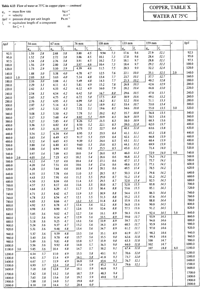
Table C4.13 CIBSE Guide C Reference Data.
Agreed there is a 2mm difference and yes I could simply interpolate between 54 mm and 67 mm from the table but for a quick and dirty answer this wasn’t necessary. Equally if I were to interpolate then I may as well get an even more accurate answer by using the mathematical method. Therefore using the various equations required from the main CIBSE Guide C doc, the mathematical solution is thus:
So it turns out word press won’t allow pasting of equations from word – rubbish!
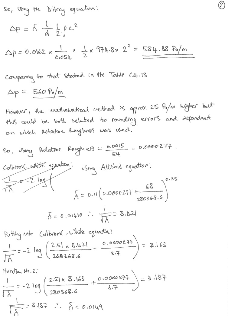
The D’Arcy equation for pressure loss due to friction:
The friction factor, λ (for turbulent flow) was obtained mathematically from the Colbrook-White equation which is more accurate than using the Moody chart:
Reynolds number:
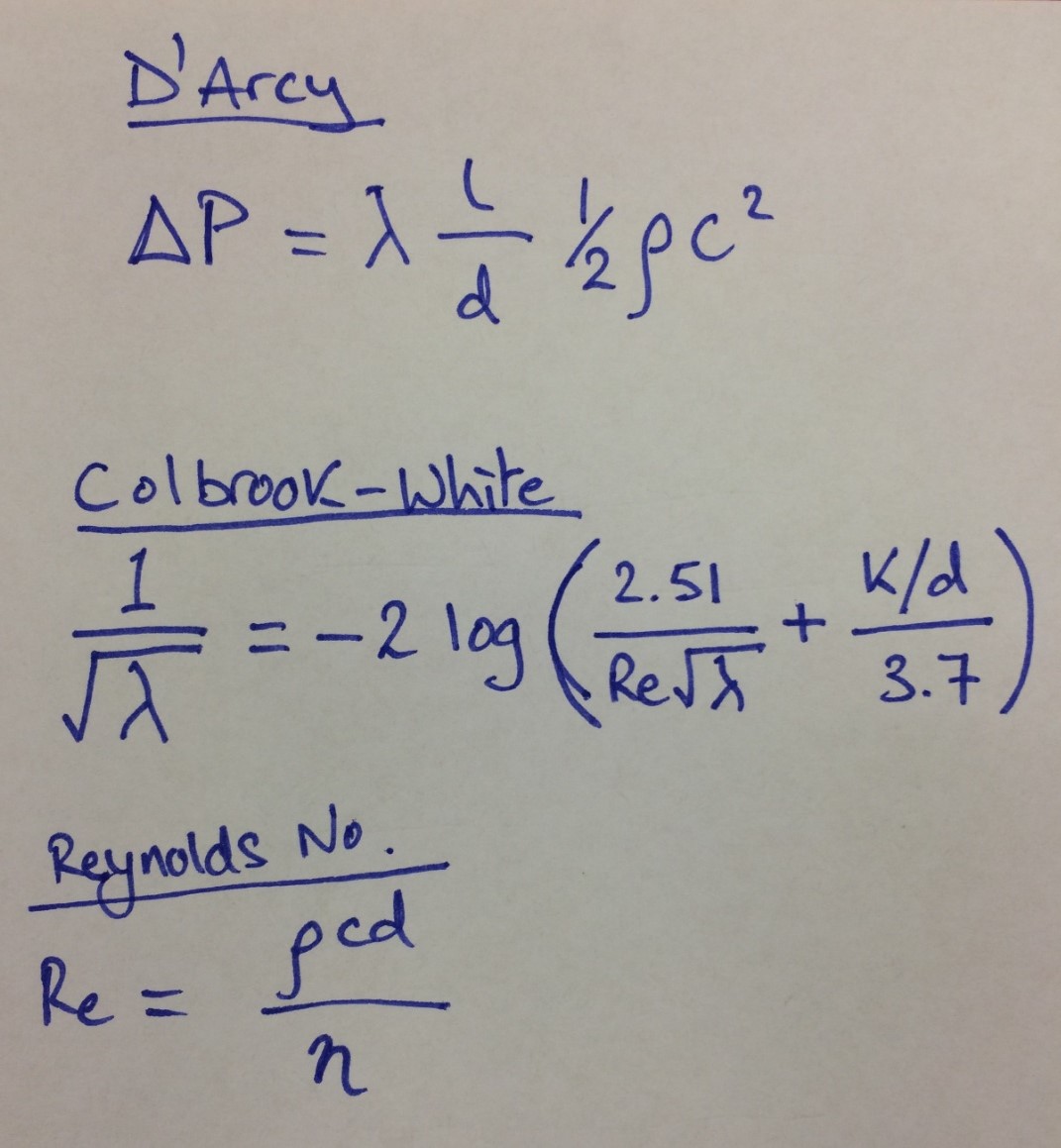
Equations for above.
Relative roughness = k/d
To determine the values of ρ (kg/m3), η (10-6 kg/m/s), and v (10-6 m2/s) properties of water I used Table 4.A1.1 from CIBSE but wanted the temp at 75ºC. So therefore some interpolation was required:
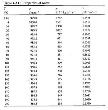
Table 4.A1.1 from CIBSE.
Using a handy interpolation equation:
d = d1 + (d2 – d1) (g – g1) / (g2 – g1)
Calculations
See below hand calculation sheet.
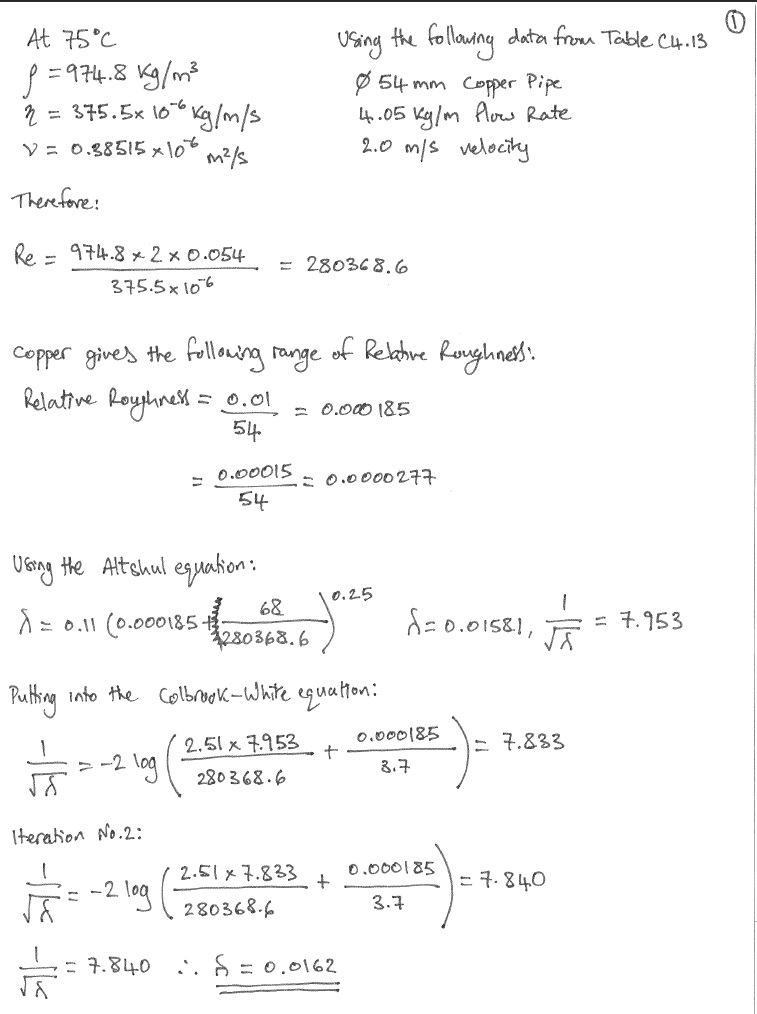
Hand Calculations – Sheet 1 of 3.
Hand Calculations – Sheet 2 of 3.
Hand Calculations – Sheet 3 of 3.
Therefore, if the schematic shows; Copper Ø 65 mm, at a flow rate of 6.63 l/s and velocity of 2.3 m/s the AIRAH charts gives a ∆P = 575 Pa/m.
Mathematically using the same process as above ∆P = 555 to 872 Pa/m.
The closest on CIBSE Table C4.13 is Copper Ø 67 mm, at a flow rate of 6.65 l/s and velocity between 2 – 3 m/s which gives a ∆P = 480 Pa/m.
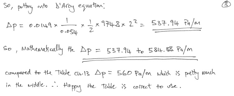
Mathematically using the same process as above ∆P = 535 Pa/m.
Findings
As a result of checking other PR pipe networks it was found that a number of pipe sections were over the max 400 Pa/m. Therefore JHG issued a Non Compliance Report (NCR) (the highest quality control level of report that gets recorded against the project) stating that we conducted a review of Fredon’s pipework and found as stated above. Both Fredon and NDY went away and also conducted a review resulting in another mtg to discuss the findings along with the contractual implications.
In the meantime I wanted to double check the material for the pipework in PR5 as the pipe equipment in BIM said it was steel yet all other plantrooms used copper. On inspection there was good and bad news; the bad news was I couldn’t find the pipework (only the main 250mm dia supply coming up the riser) but the good news (related to the bad) was it hadn’t been installed yet hence no pipework found. This meant that any pipe sections diameters could be changed thus avoiding an expensive rip-out and re-install.
Steel is cheaper to purchase and more wear resistant than copper however, copper is easier to install (brazing method vs welding of steel) and thus saves time and therefore cost (making copper cheaper overall).
The outcome of this mtg was both NDY and Fredon used pipe sizing charts from the Australian Institute of Refrigeration, Air-conditioning and Heating (AIRAH) Technical Handbook to select their pipes but we couldn’t figure out whey on the same schematic (same velocity and pipe size) they were getting different pressure losses.
We asked Fredon to send us their AIRAH charts and after further investigation we found the error.
NDY say they designed all pipework using steel however their design brief for piping material talks about various materials but doesn’t actually state a design material. Also, there is no mention of material type on any of their schematics. The design brief states:
Pipe sizing on the drawings for pipe fluid velocity, friction rate and pump head calculation are the standard method of size identification for that material e.g. mild steel pipe – DN (nominal bore); copper pipe OD.
Where alternative pipe materials are scheduled as acceptable, the nominal bore of the alternative shall be equal to or greater than that of the nominated mild steel pipe DN.
Fredon made the value engineering decision to install copper and therefore should have understood that when comparing steel and copper the industry norm is to refer to them using their ‘nominal size’. As quoted from the Australian Standard (AS 1074 – 1989)
‘1.3.5 Nominal size (DN) — a numerical designation of size which is common to all components in a piping system other than components designated by outside diameters or by thread size. It is a convenient round number for reference purposes and is only loosely related to manufacturing dimensions’.
However, they should have also realised that steel’s actual internal dia is larger than the stated nominal size compared to copper’s actual internal dia which is smaller than the stated nominal size (copper’s nominal dia is almost akin to the OD (external dia)). This can be seen from the internal pipe sizing table at Table 4.2 CIBSE Guide C and the AIRAH charts below. This comparison is the same for both the UK and Australian construction industries, however, AIRAH present their charts with both materials having the same nominal internal dia and this is what caused the confusion resulting in the errors. NDY designed the pipe networks using steel pipe (e.g. 32mm dia gives 400 Pa/m) but when Fredon changed material to copper they simply used the same 32mm dia pipe. But a copper 32mm nominal pipe has an actual internal dia of 29.26mm which is smaller than the steel pipe’s nominal dia of 32mm (actual internal dia of 36mm) hence over a 6mm dia difference which creates higher pressure losses.
What Fredon should have done was compare the two AIRAH charts by material and therefore upsized the nominal dia of copper pipe to 40mm giving an internal dia of 35.61mm therefore meeting the design brief and thus ensuring a similar pressure loss to that of steel – not exceeding 400 Pa/m.
The charts below show the pressure loss of 82ºC water in both medium steel and copper pipe and compare three different pipe sizes to show the effect the material has on pressure loss.
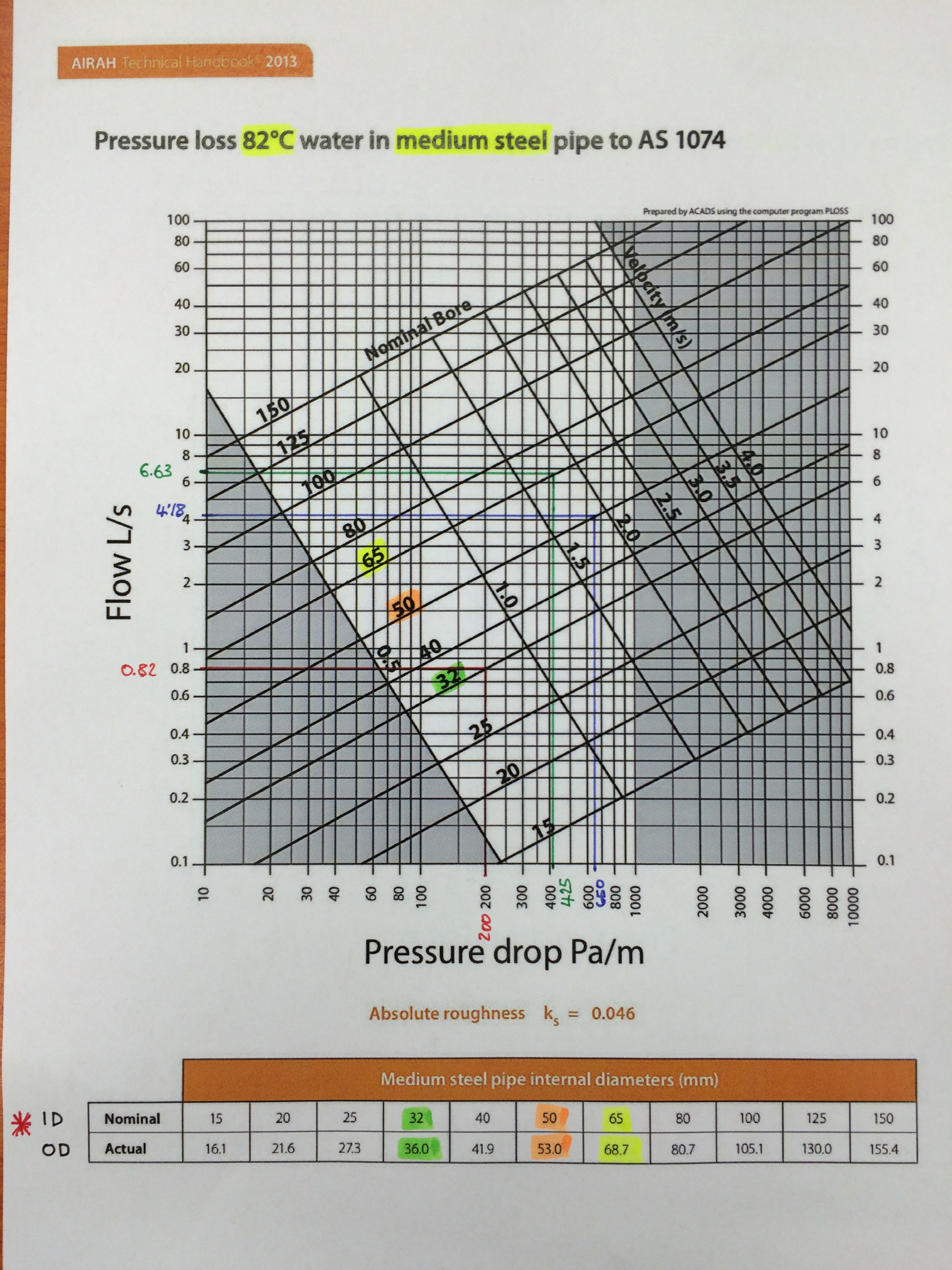
AIRAH Medium Steel Pipe.
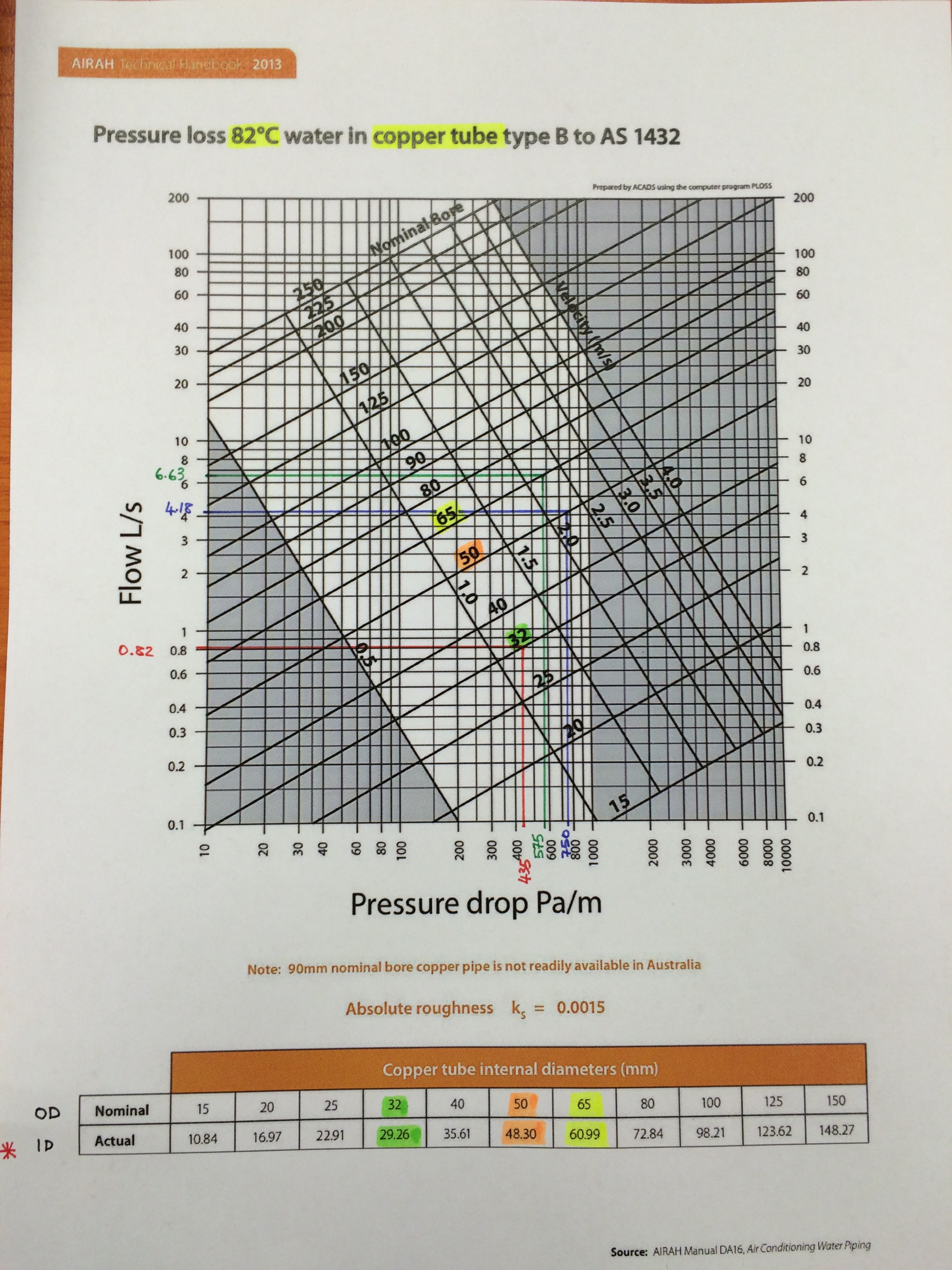
AIRAH Copper Pipe.
So you can see, assuming that you can change from steel to copper pipe (without identifying the nomenclature change AIRAH uses) is incorrect and results in under sizing your pipes thus increasing pressure losses.
This is why the CIBSE Guides and the UK construction industry, on the whole, use different standard pipe sizes for different materials to avoid this confusion. The table below is an extract from the CIBSE Guide C.

Table 4.2 CIBSE Guide C.
So What?
Technically, why does AIRAH refer to both steel and copper piping on their charts using the same nominal dia knowing the actual internal dia is very different?
Why don’t they use a different nominal dimension for say copper like they do in the UK and then have charts that reflect this like Table C4.13 from CIBSE Guide C?
The only dia that actually affects the flow rate and thus pressure losses is the internal dia (the A in Q = A x V), the nominal/OD and wall thickness matter not.
Commercially, JHG need to establish between NDY and Fredon who is the cause of the issue that means JHG currently don’t meet the Client’s brief. They need to establish the extent of what is required to resolve the issue and commercially who will pay for it. When taking into consideration the increased running costs over the lifecycle of the system with pressure losses above 400 Pa/m vs the project resolution (measured by cost and delay to project completion) of ripping out and re-installing new pipework, it could be argued that the latter would be much more expensive. Additionally, Fredon say the pipe runs that are above 400 Pa/m (in most instances around 550 Pa/m) are relatively short and thus the extra cost associated to the inefficiency would be negligible. In which case Fredon would rather pay the yearly additional cost for the lifecycle of the system rather than rip out and start again. Clearly not the point and goes against the Client’s brief and more importantly trying to achieve a system with the best possible energy efficiency thus helping to reduce carbon emissions.
Resolution Options
More importantly, to reduce delays, the resolution is the primary focus. There are two viable proposal options for the Project Director and the Client to discuss: both require proving the extent of the problem and then either; order Fredon to replace all incorrect pipework in PR’s 1 and 2 only (index run) and then request dispensation for the remaining incorrect pipework (doubtful); or order Fredon to replace all incorrect pipework throughout the building. Both have commercial and time implications but the second option could potentially bankrupt Fredon. Therefore, a key factor both JHG and the Client need to seriously consider in order to avoid unnecessary delays are the potential second and third order effects of having to get a different mechanical subcontractor to complete the works (with respect to meeting the project’s practical completion deadline). Either way JHG will still carry the problem to solve on the Client’s behalf.
Conclusions
The above findings don’t resolve the issue but will aid in leading to the correct commercial outcome. Fredon say they were following the NDY design schematics in which case 32mm pipe is correct but only if the schematic doesn’t state steel pipe. If the schematics do then Fredon, deciding to use copper, should have up-sized to 40mm as described above. So, JHG need to establish the material stated on NDY’s schematics in order to identify the faulty party. The truth is that neither NDY nor Fredon are squeaky clean and so commercially they may both end up paying for the resolution.
To resolve the issue JHG are looking primarily at replacing only the incorrect pipework on the index run (PRs 1 and 2). Through Fredon’s as-built drawings they should be able to establish which pipe runs are over 400 Pa/m and by how much and then estimate the extent of time and cost to replace them. Both of which JHG and the Client have a vested interest in keeping to a minimum.
The meeting this coming Monday will be very interesting and I will blog a subsequent update on the resolution and commercial aspects as they come to light.
Recommendations
It could be recommended that AIRAH change their pipe sizing charts to reflect those of the UK construction industry like those produced by CIBSE.
In other news
My collection of sports equipment is steadily growing so I have found a new hobby to help pay for it!
There’s snorkelling gear and a kite surfing training kite on the shelf too!

That’s my winnings!

Fran
Ah, the old CIBSE student guide – I would check with the concise handbook or Guide C however, you may find that the tables have changed when the guides changed. This could make your plight better or worse but the problem will still be the same, specification by pressure drop and velocity – no wonder people are chasing their tails.
Are you sure that there is an inefficiency in the greater pressure drops for the small runs? Accepted that pressure drops on the index circuit are non negotiable but on branch lines wasting pressure to achieve the correct flow rate is not a bad thing, it limits pipe size and makes the commisisoning set work easier – you may be able to use this to come to a sensible resolution.
Good TMR topic here – look back at the article we discussed “pipe sizing for life cycle costs” and have a think about using that as the basis for a bit of analysis. You may even look at how contractors can install the work commisioned through consultants yet be responsible when it doen’t work, oh to be a consultant.
Mark,
Thanks for your comments. There may not be too great an inefficiency in the smaller runs but as the principal contractor we have to give the client what they ask for. Agreed the significant branches are those on the index circuit and that is why we are hoping the Client will, with a little scientific explaination from us, only demand we (via Fredon) put that pipe section right. Therefore, giving us dispensation for the remaining not so critical branches on the other circuits.
I was thinking as I wrote more and more that I could quite easily turn it into a TMR. I have just looked back over all my notes and can’t find the “pipe sizing for lifecycle costs” article. Do you have it or a link to it you could send me pls?
I understand what you mean about the subbie being left having to answer for the problems of poor design by the consultant but in this case, based on the evidence, they are probably more in the wrong.
Fran, understood. The lifecycle pipe sizing paper is on the ELE (refrigeration module)
Hopefully you can convince the Client that the critical elements are being addressed and maybe, highlight the problems with a specification that is too tight.to make sense!
Mark.
Mark,
After reading your email and also noted from your first comment, I only used the CIBSE student guide to quickly find the equations but then when I realised it didn’t contain all of the pressure drop tables I had to revert back to CIBSE Guide C anyway. So all my figures are based either from Guide C or hand calcs.
I completely understand trying to help out the subbie where possible for any future back-pocket return favours and limiting the re-work to the index run is definitely our focus in terms of getting to practical completion. But…this particular subbie have been very poor and I sense JHG management are apathetic to their outcome. They do however understand we need to get the job done so don’t really want to see them go under.
Thanks for the CIBSE spredsheet – very handy!