Archive
Site Two Fifty One – Drainage and Confined spaces
Site Two Fifty One – Drainage and Confined spaces
Drainage
It was about time we had a drainage dilemma – my view is there will always be uncertainty when connecting to existing foul water sewers and unsurprisingly we have encountered a problem.
To put it mildly Manhole 02 has been a mess-up from the start. It is a new manhole with the purpose of connecting the site to an existing Thames Water pipe. Firstly the drainage drawing had it positioned in the wrong place. See the drainage drawing grid line B and structural drawing grid line B. Man Hole 02 is closer to grid line B in the drainage drawing than in the structural drawing.

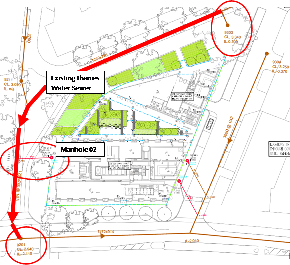
Drainage Drawing showing location of new Manhole 02. Note proximity to grid line B.
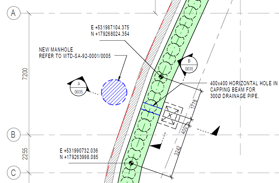
Structural Drawing showing location of Manhole 02 further away from grid line B.
So to fix the problem, as the issue was realised after constructing the manhole, a new header will be constructed – not hugely difficult, but it will cost someone something (more below).
Here is the real issue – Invert Levels.
The drainage drawing of the existing Thames Water sewer invert levels looks to be correct. Invert levels taken at other existing manholes gives a pretty accurate picture. However when the heading from Manhole 02 was excavated towards the existing sewer no existing sewer was found. Mystery?
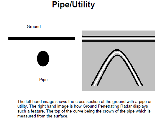
Earlier in the year a ground penetration radar survey had been done to identify existing services. At the time it showed that there were pipes under the ground so everyone was content. However, on further analysis of the study it appears the following was found:
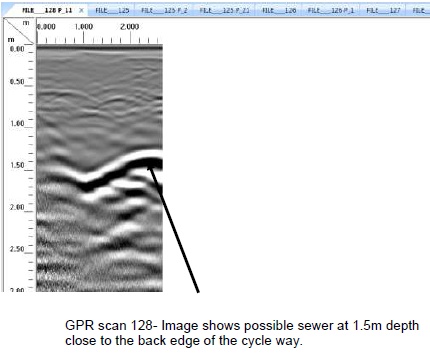
Print screens from the GPR report – pipe identified at 1.5m below ground level.
The GPR survey showed the following:
Ground level: 3.15m AOD
Pipe depth: 1.5m below ground level
Pipe diameter: 1.28m
Therefore invert level of the actual existing pipe: 0.37m AOD
The issue?
Going back to the drainage drawing the Invert Level of the Manhole 02 connection to the sewr is given as -1.109m AOD. Last time I checked water flowed downhill…
So why was the Invert Level designed at -1.109m AOD. Good old interpolation it seems. An upstream and downstream set of invert levels were used to interpolate between to give a connection invert level. Good idea, but as there is no pipe there it seems somewhere beyond the connection point the sewer drops down – i.e. runs at two gradients. (1 in 53 gradient now seems a bit steep).
So what?
For a start the issue is not resolved yet. There is little point burrowing around until we find the pipe. A drainage team are being employed to run a camera down the existing pipe to understand what it does. More onerous for the designers the difference in height of over 1m puts the inlet into the building higher within the basement level 1 floor – I am sure that can be overcome, but again someone will have to pay for that change. As we are still pre-contract, novation not yet occured, I suspect Laing O’Rourke will push the client to pay.
Health and Safety
This week we had a health and safety stand-down. This was not due to an incident on my site, but as a bit of a pre-emptive measure because there have been a number of reportable incidents on other Laing O’Rourke sites of late. We got the workforce look around their work areas and identify hazards and press home the importance of keeping walkways open and clear. A useful exercise, if nothing else to reinforce how important safety is on site and that starts with the basics of access.
You would almost have to try and obstruct a walkway as much as this!
Later in the week we had a Laing O’Rourke Safety Leader visit. The site was looking far better than it has done – segregated work areas, banksmen, coordination, signage and it generally appeared tidy. However, we have a sub-contractor, Murphy, undertaking works to install further manholes (and to fix the debacle around Manhole 02 I have mentioned above).
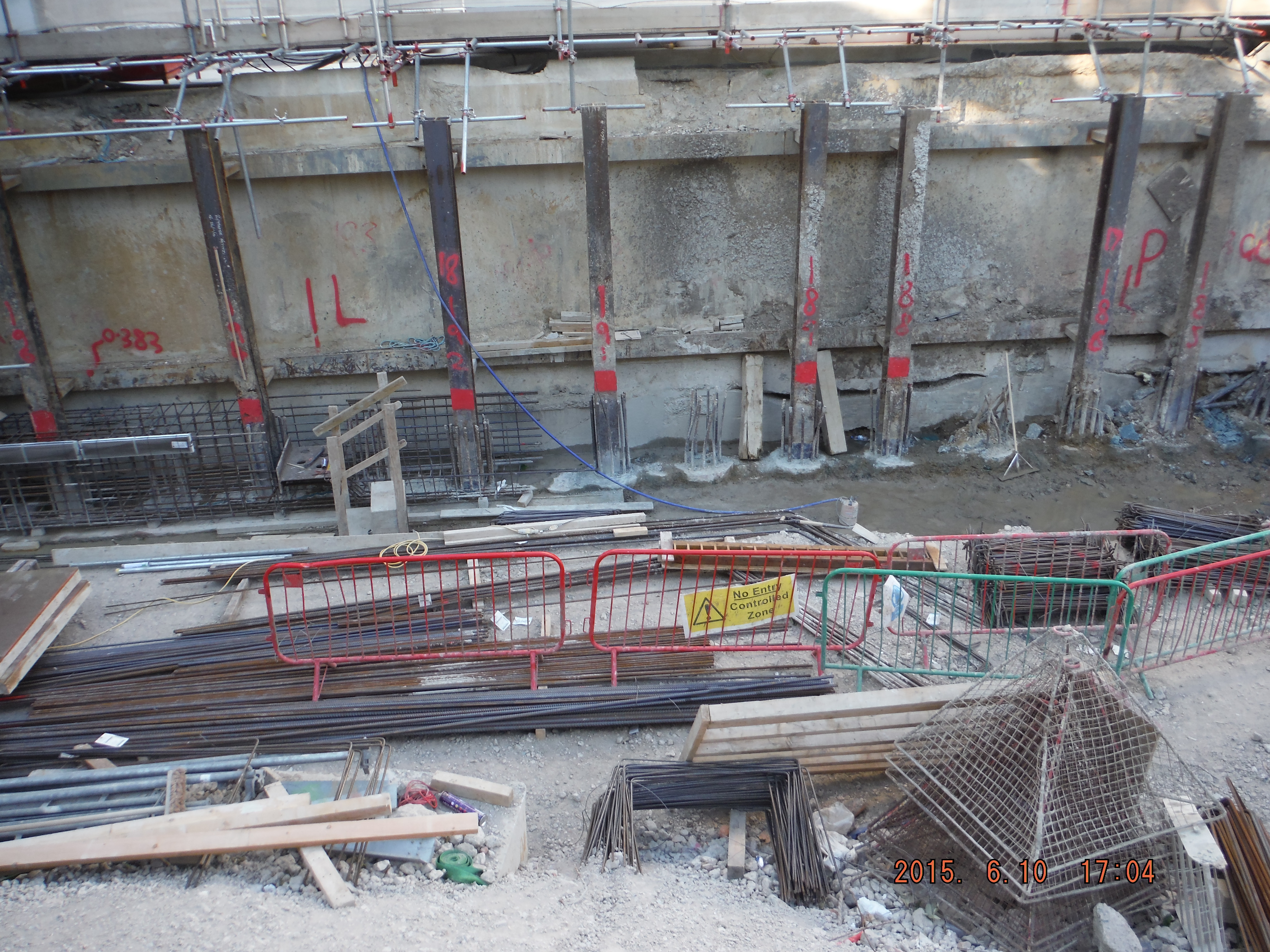
Manhole 02 temporarily paused while the connecting (existing) sewer is found.
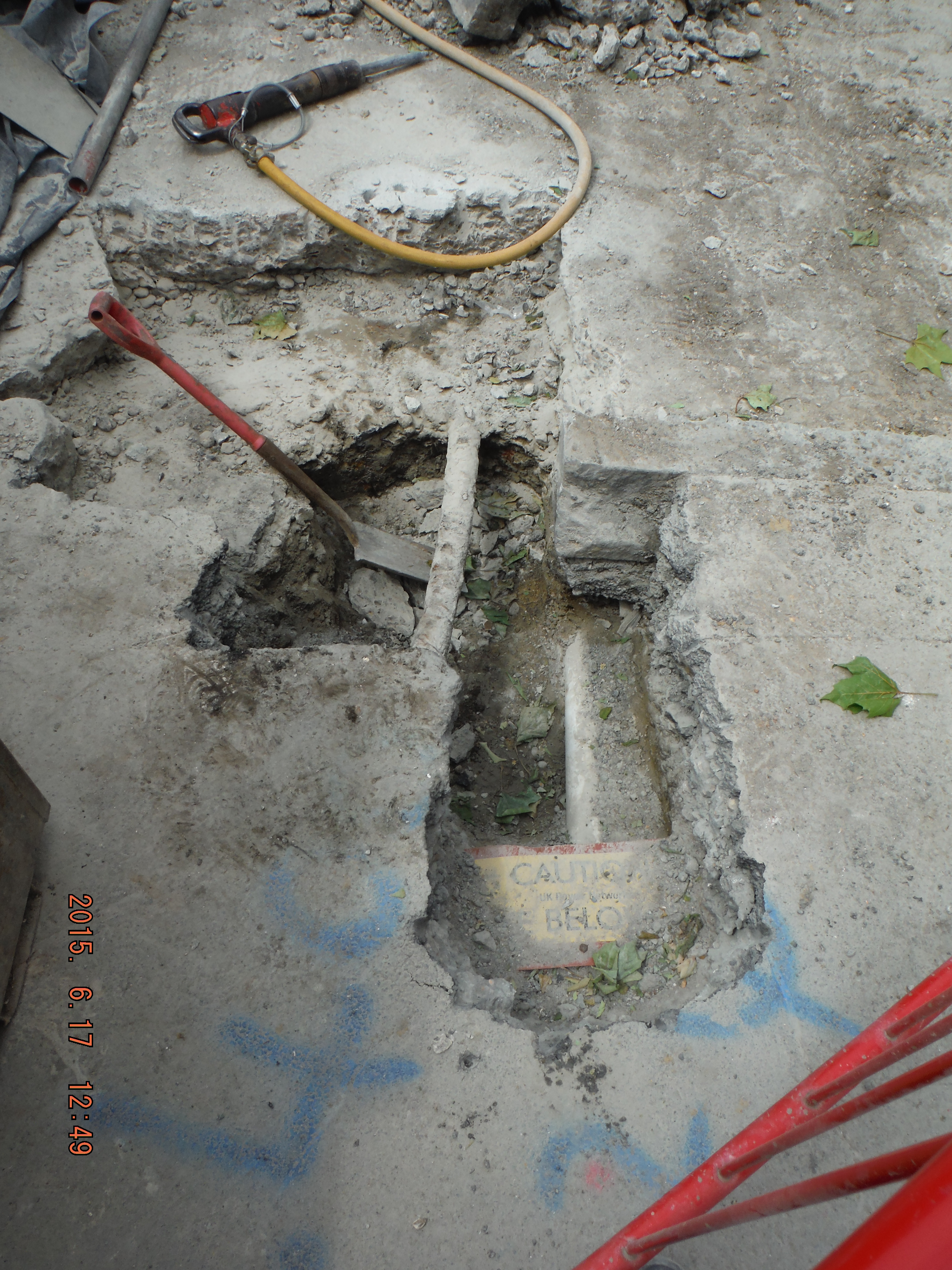
The start of Manhole 03 – plenty of existing services to deal with.
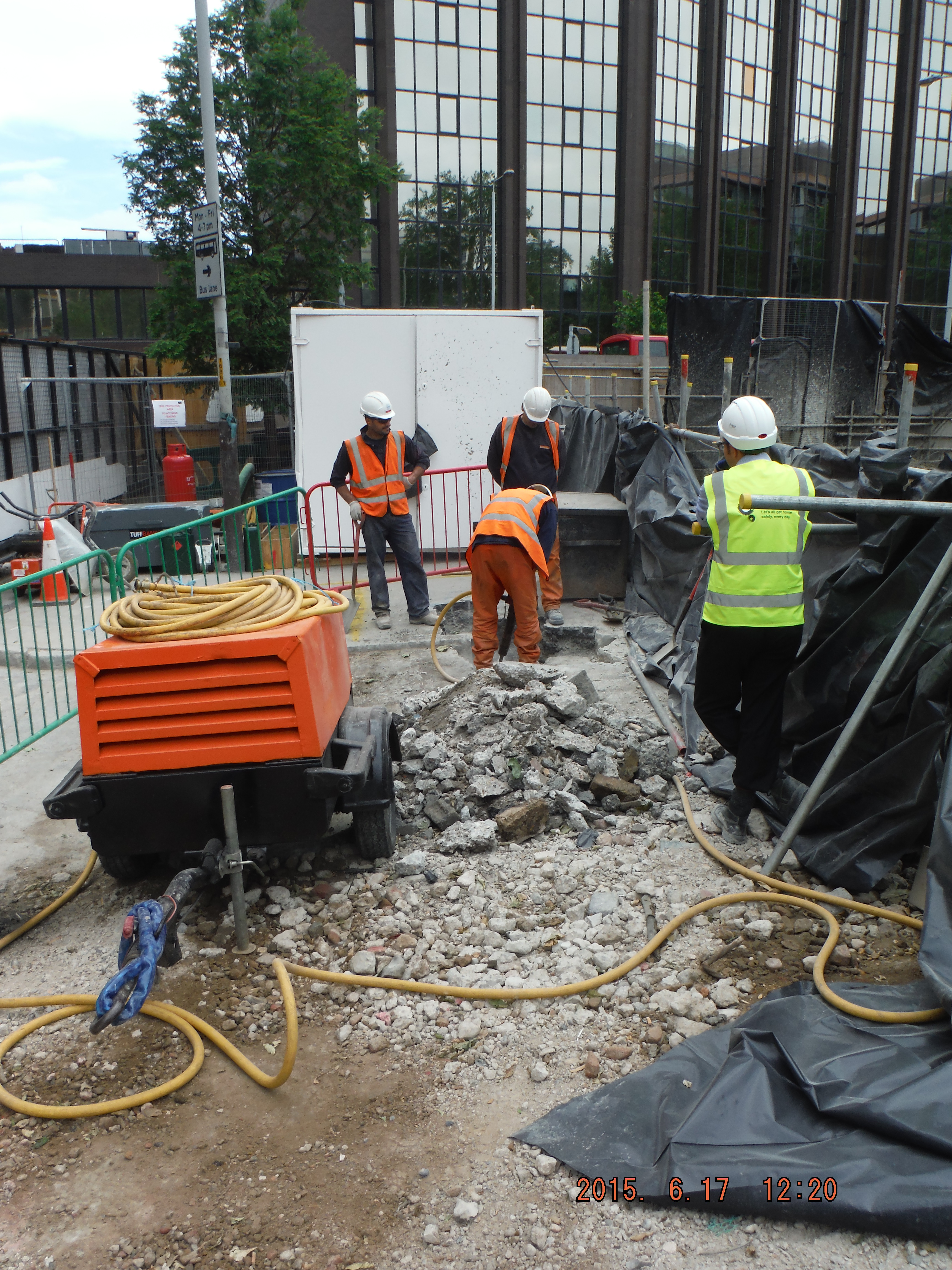
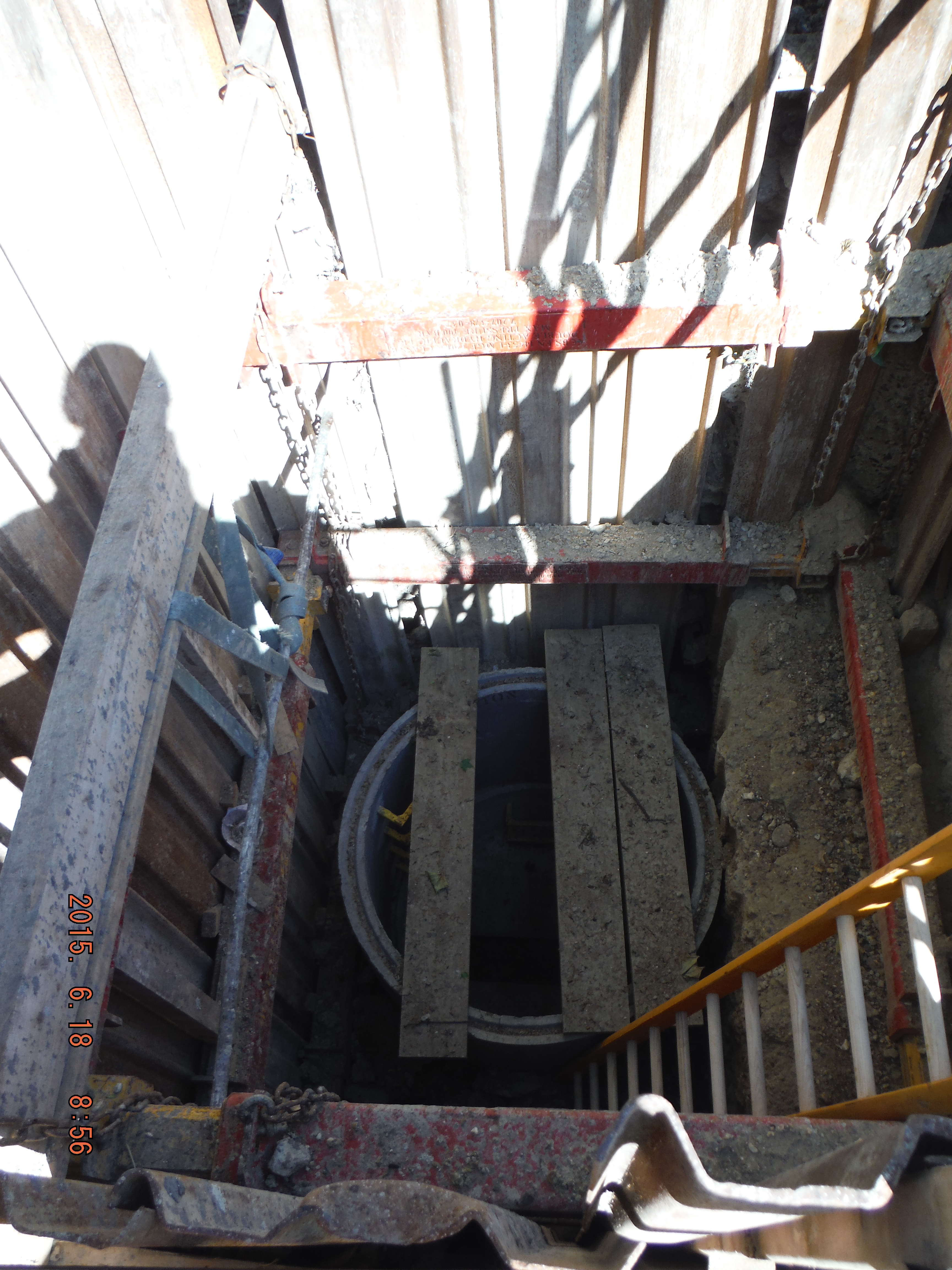
Manhole 03 – confined space approaching as the hole is deepened. Compressor fumes settling into the hole (confined space) present a significant hazard.
The question was asked, from the Main Contractor (Expanded Structures in this instance, filling the One Team role of working for Laing O’Rourke), who is confined spaces trained? The second question was, what is a key hazard of working in confined spaces? Not my answer, but one I might have given is: structural integrity of the hole being dug. No – fumes from both the compressor an excavator filling the hole so when the operative enters he gets into difficulty. Clearly the Murphy operatives need to be trained in confined spaces, but so does the main contractor.
So What?
“Under domestic law (the Health and Safety at Work etc Act 1974) employers are responsible for ensuring the safety of their employees and others. This responsibility is reinforced by regulations.”
The Confined Spaces Regulations 1997 contain the following key duties:
avoid entry to confined spaces, eg by doing the work from outside; (not possible)
if entry to a confined space is unavoidable, follow a safe system of work; (yes in place) and
put in place adequate emergency arrangements before the work starts. (yes in place)
Even though safe systems of work have been checked, because there is deemed to be a lack of competence (no training) of the main contractor to supervise the works, this must be rectified and an appropriately competent person will need to review the method statements and emergency procedures.
Reflecting on this – it now seems pretty obvious that to adequately approve a sub-contractor’s safe system of work, the main contractor must be trained (in this case in confined spaces). The question is what is competent. If it is where all practicable measures have been taken to reduce risks, then we fail – experience without training is perhaps another way of saying it worked last time so it’ll be alright this time – i.e. a dangerous place in be and we are not even in the hole yet!
Finally a couple of concrete finish photos: F5 (flow not slump), C40/50, Waterproof concrete…
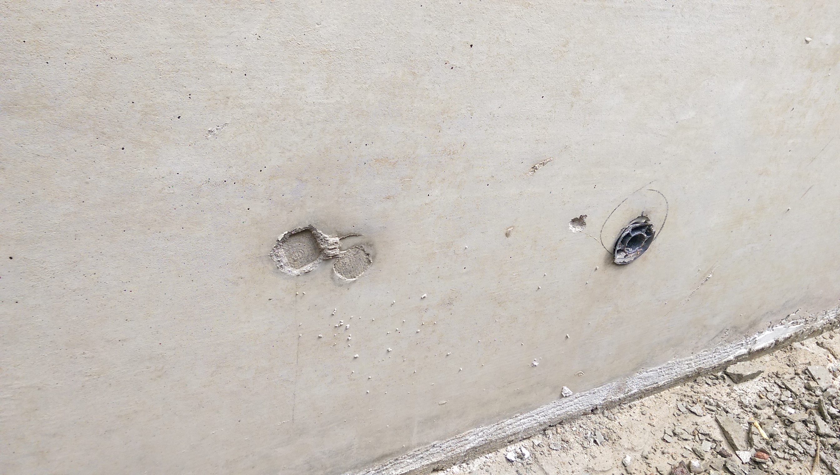
Decent finish, shame about tie bar holes.
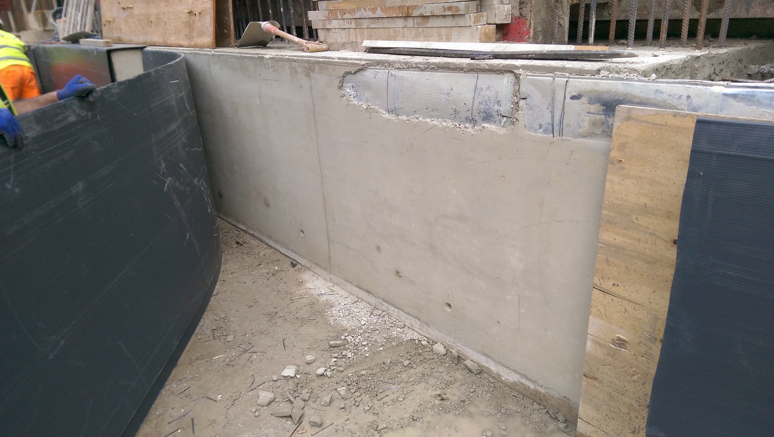
Cordek plastic sheet being used to protect the face of the capping beam. Kwika strip being revealed at the top of the beam.
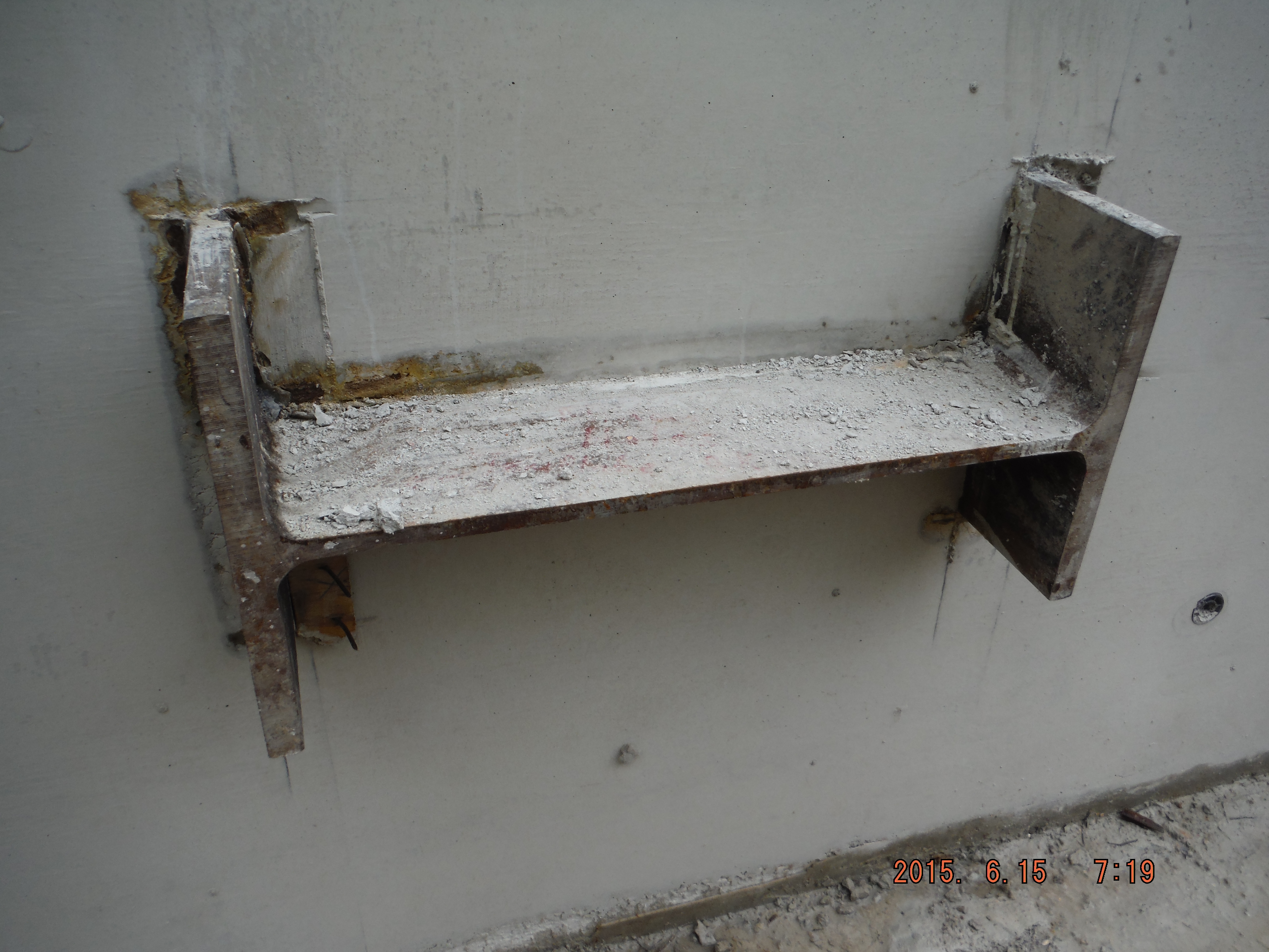
Shear stub for props – note fibre board used to create a recess around it to allow the stub to be burnt off and made good many months down the line.

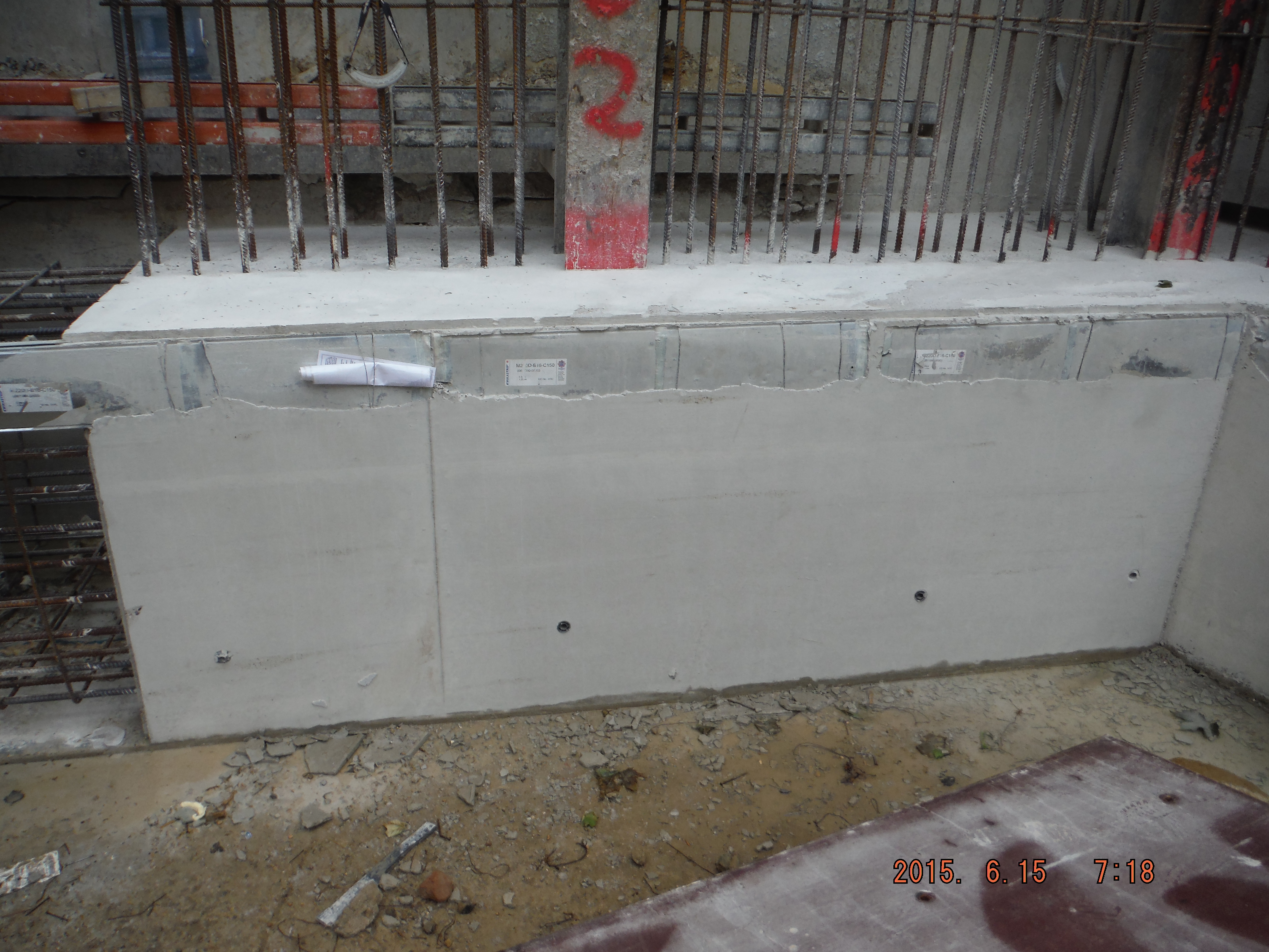
More of the same – note blinding layer at base of capping beam to be removed during excavation of ground.
