Archive
Mortar, PT and Mily Cyrus
Two points of interest this week.
Firstly the Mortar Silo. This is not where we store the mortar rounds on site. My site is in West London, not America and therefore we have no need for heavy armourments to protect against the gun toting British, gun toting police or indeed gun toting population.
It is in fact where we store the mortar for the Blockwork. A package I have been given to look after. “Sort out the silo” I was told. “Easy” I thought (once I’d googled what one was). Oh how wrong I was!

The first question I tried to answer was “where should it go?”. Our construction manager picked a spot, then went on holiday for a week. In his absence everyone else agreed that was a stupid place to put it. So another spot was picked with the assistance of the man from Tarmac who came to site on a recce. The silo requires water and power. The location chosen is against a fence along which the water ring main runs – so a tick there. It’s also next to a large steel portal frame building where prefabrication will occur. That building has lights and stuff so I thought the electrical bit would be fine. Wrong again. The building does have electickery but it’s not turned on. And won’t be until the road has been dug up (again). I’m hopeful it will be on in time but I’m not so sure.
Next it needs to sit on a concrete slab. This slab must be 400mm deep (to accommodate some holding down bolts) but cannot be higher than 100mm from ground level. So we need to dig a hole. In a car park. Made of concrete. Laid on top of cobbles. With train tracks in it. Oh dear.
Then there’s the bolts themselves. Tarmac sent me the spec for the bolts but couldn’t send me setting out details since the silos are apparently made by someone with the accuracy of the Royal Artillery and therefore no two are the same. The only way round it is to sit the silo on the slab. Drill through where the holes are and attach the bolts all while hoping it doesn’t fall on you. So we’re going to use our massive forklift to hold the Silo in place while we mess about with the feet.
So it looks like I’ve sorted it, or at least I would have if the Blockwork sub-contractor would tell me how many of the things he wants!
My other headache this week was the PT slab. The first one should have been poured on Wednesday, but the designer was working for PC Harrington, who didn’t pay them. So McAlpine paid them and they did the work. The pour was then rescheduled for today. It isn’t happening. It was discovered yesterday that Arup (the principle designer) had designed the building with a certain tolerance for differential settlement between the building core and the surrounding slab. This was published in their “movement and settlement report” which was issued to PC Harrington for onwards dissemination to the PT designer. It never got there. So the PT slab was designed with a different set of applied forces to that which Arup thought it should. Arup ran some numbers and told the PT designer that they’d have to do it again increasing shear by 12%, bending moment within the slab by 10% and (this is the biggy) punching shear by 38%! The PT designer is not happy. They think that they’ve done what they were asked since the Arup PT spec doesn’t mention the report and they were never given it anyway. They say the recalculations will take 3 days and cost “thousands”. After the calcs the additional steel will need to be ordered, delivered and installed. So we’re probably looking at a week delay and the associated penalties.
McAlpine blame PC Harrington for this (along with the current delay, the poor quality concrete finish, third world poverty and Mily Cyrus). PC Harrington think it’s Arup’s fault as their spec doesn’t specifically mention the requirement to design in accordance with that report. But it does say that all “relevant reports” should be considered. I would say that the bit of paper that quantified the differential settlement is fairly relevant.
Previously I spoke about how people within Arup weren’t talking to each other and therefore the drainage and the reinforcement steel clashed all over the place. That was clearly a communication problem. So is this. There have been numerous examples where a specification or a drawing says something that is ambiguous, as a result the product is not quite what the designer intended. Some of this is inevitable, it is the shortfall of language. But some of this is down to people using flashy words when they don’t need to. It not just a military problem. While I’ve not heard anyone ask for “greater granularity” on anything yet, I have heard loads of people attempt to describe something in words when they should just draw it, or use clever sounding words when they should just use plain English. This is particularly relevant when a lot of the people who do the lower level design work don’t speak English. Or at least not any better than I do.
So if part of the point of AMRs, TMRs, essays, etc is to ensure that PQE Officers can write in clear English – I say good. And for future courses maybe there should be more of them. Along with stretcher runs, drill and CBRN training obviously!
Finally a shimpf: a few weeks ago I posted a link to our justgiving page for sponsorship for an event. The support has been somewhat underwhelming. I know its not a military charity but I do think it’s a good cause. It all goes towards improving infrastructure in some of the worlds poorest places. Places most of us have seen and so probably understand how shit it would be to live there without clean water or electricity. Please help!
US Measurement system
My biggest fear coming out here on attachment was the measurement system, besides people with guns and the MVA. It is essentially an archaic foreign language with little real utility in the modern metric world; a little like Gaelic. The best way to deal with issues like this is obviously to avoid them that is a little difficult here so I’ve had to just roll with it and enjoy the chaos.
This blog is not meant to be a definitive list of all forms of measurement, for that there is Wikipedia, rather a quick run down of the ones I’ve come across to help anyone coming out here on attachment in the future and also anyone that finds themselves in the economic shadow of the USA. Places, as Nick West has found out, like Montserrat use the US measurement system because the US is their chief supplier.
A few things to note are: firstly, the US measurement system is that it is not the same as British Imperial measurement. It’s mainly the same but not always, so beware! Secondly, the descriptions of how they came about are entirely logical as a unit of measure from when they were thought up. They just don’t really combine together quite as well as metric when combined and some funky factors start coming out. The big danger in trying to convert backwards and forwards is that calculator errors start to add up and cause issues with suppliers trying to over charge you for ‘non standard’ items.
The simple ones:
Feet (ft or ‘) and inches (in or “): Simple stuff, 12 inches to a foot, 3 feet to a yard. When you start to go smaller than an inch fractions are often used. On drawings the rough rules are: less than 2’ all measurements will be in inches only, after that feet and inches are mixed.
Pounds (lbs): 0.454kg. Straightforward, there is no use of the stone, but the hundredweight is used which is, as one might imagine, 100lb or 45.4kg.
Liquid Measure: Mainly for cooking and fuel to be honest but kids are taught: ‘two cups to the pint, two pints to the quart, four quarts to the gallon.’ Key points to remember here are that both the pint and gallon are smaller in the US than in the UK. That means that the people are less accomplished drinkers and that cars seem less efficient (not the only reason they seem less efficient!). A US gallon is 3.79l and a pint is 473ml.
Fahrenheit (F): The weather is as much a topic of idle conversation as it is in the UK. The difference being that out here it swings wildly across the seasons but the conversion is pretty straightforward. Fahrenheit = 1.8xCelsius + 32.
Where it starts getting interesting:
CFM because it takes too long to say cubic feet per minute is used for airflow in ventilation systems. 1m3s-1 is 2119fcm; which is close enough to 2000 for mental arithmetic.
PSI is pounds per square inch, which we are used to for car tyres etc. When speaking about gauge pressure it must be remembered to add 14.6 psi for atmospheric pressure to get the absolute pressure.
And onto my favourites:
BTU stands for British Thermal Unit, which I have personally taken the blame for on a number of occasions already. For dinner parties it is the energy required to heat one pound of water by one Fahrenheit. It is equivalent to 1055 Joules, fortunately close to 1kJoule!
Ton. Also called a ‘ton of refrigeration’ this is the heat absorbed by melting a short ton of pure ice at 32F in 24 hours. Out here it seems to be exclusively used for large chillers in HVAC units but is equivalent to 3.5kW.
Footcandle (fc). This is a measure of illuminance and is simply the light given out by a candle at a foot. This shows the weakness of the customary units as illuminance should be measured as luminous intensity per unit area. Fortunately its difficult to measure this with any more than10% accuracy and 1 fc is 10.7lux so close enough to 10 for measurement.
So that’s ‘how for now’. I assume some imperial units are still used by the old and bold out on site in the UK as that’s how people learnt their trades. What is it like in Australia? I’m sure Howard and Brad will have seen some pretty funky civil units! Please feel free to add any more in the comments section that people have seen. I will try to keep this up to date more as I go through the attachment.
Sundrop Farms Update
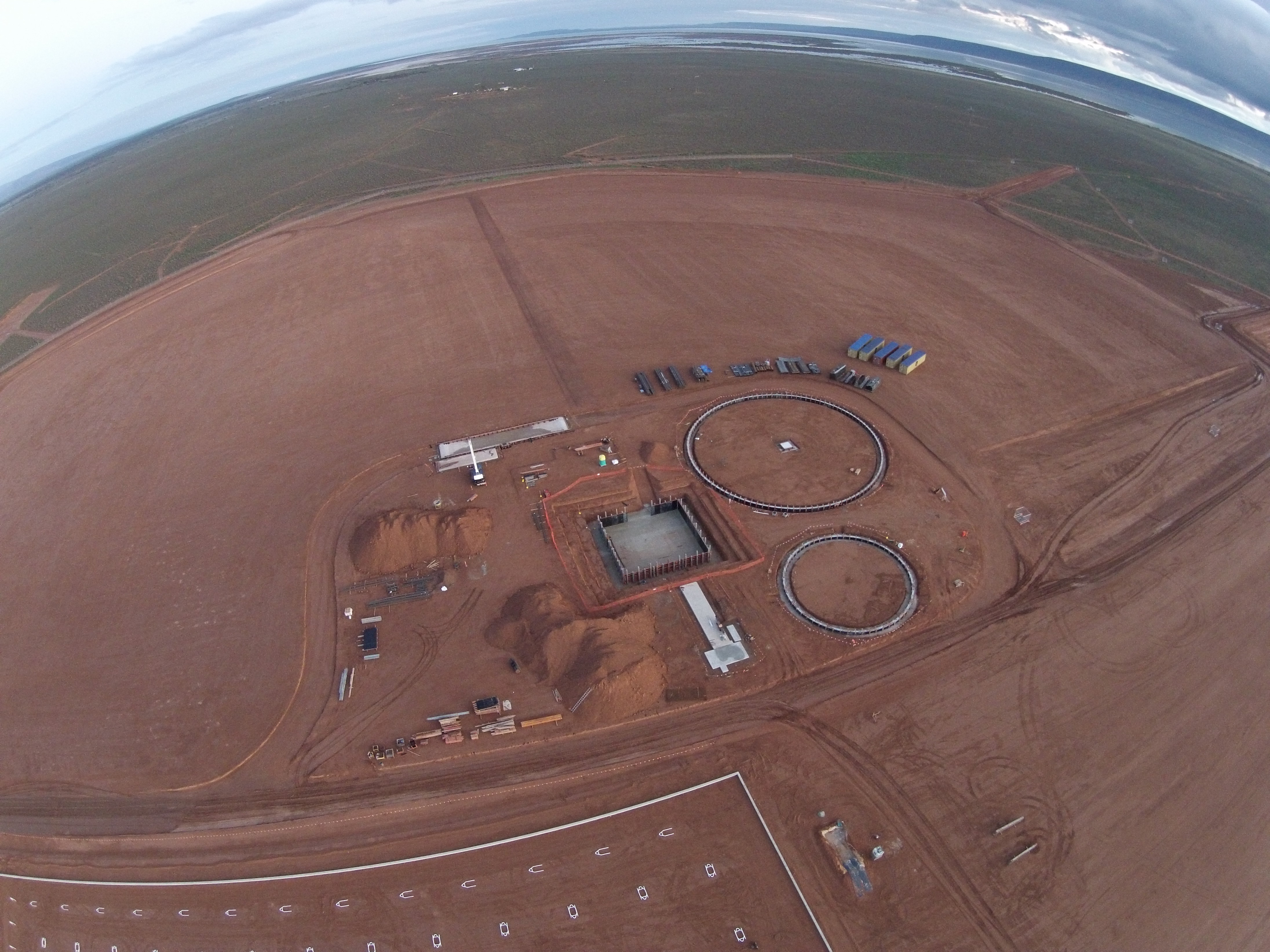
This blog aims to provide an update on the Sundrop Farms project to date and highlight a couple of issues currently experienced in site. In terms of progress the photographs below were taken by the client using a drone and summarise where the project is up to. The first photo shows the power island and some of the foundations now getting poured. The two circular foundations are for the two Thermal Energy Storage tanks, the larger has a capacity of 22000 m³ and will maintain the water at a temperature of 95 °C and the smaller has a capacity of 6000m³ and will maintain the water at 43°C. The square foundation in the centre is for the solar tower, currently we are waiting on site for 200 bolts, 4m in length that will sit within concrete for the base plate of the 115m tower to be bolted to. The tower itself is based on the design of a wind turbine tower and is getting manufactured locally. For a sense of scale you can see the 40ft iso containers positioned in the top right of the photo.
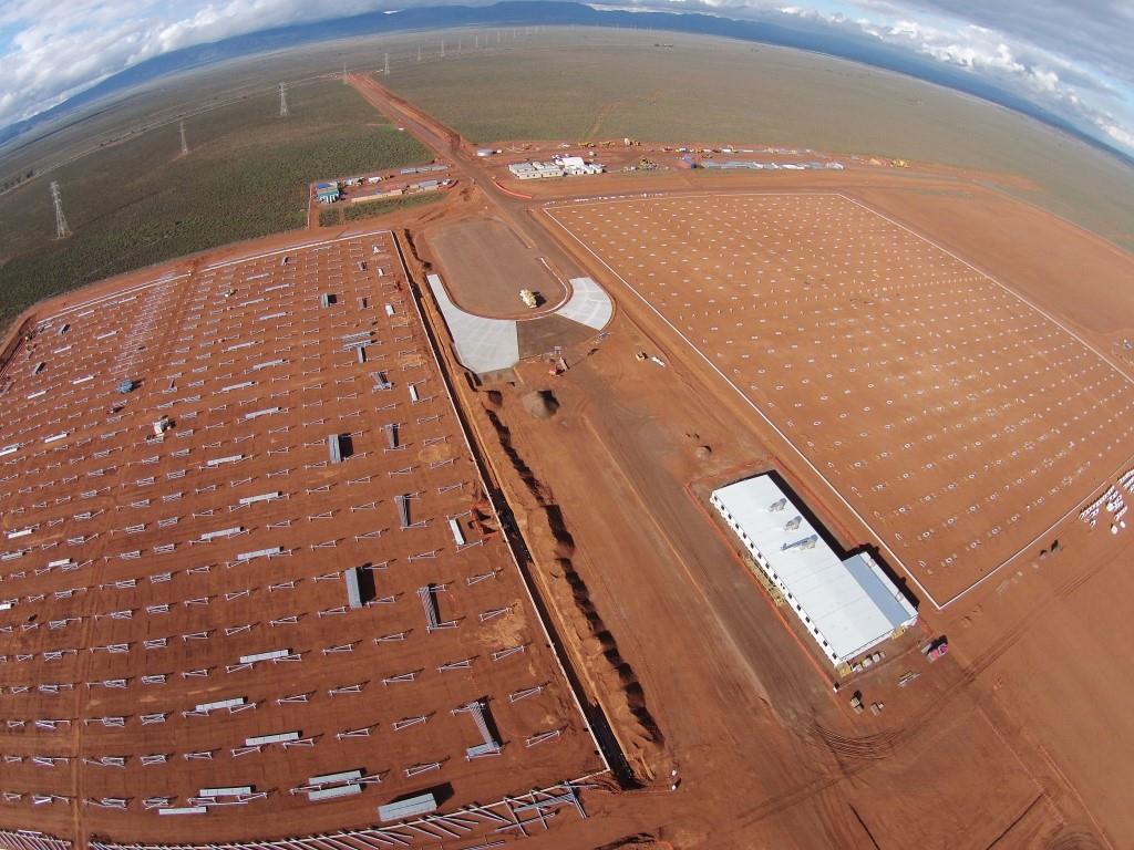
The progress on the greenhouses can be seen on the photo below. The first two greenhouses form part of Separable Portion 1, construction on the one on the left hand side of the photograph began in Apr 15 and the erection of the steel work that forms the frame of the greenhouse began last week. The amenities building is the complex to the bottom right and comprises of 16 modular buildings that have been lifted into position and fit out over the last 8 weeks. One of my responsibilities so far has been the management of the installation and the final inspection of the complex last week. Following the handover the subcontractor attempted to submit their practical completion notification certificate. On looking over their contract there was no definition of the term practical completion or mention of the certificate and what this means. The definition of completion was given, but part of the definition was the requirement to have completed the commissioning, with power, water or sewerage connections currently not in place this cannot happen. The completion of the building also marks the start of the liability period, so clearly it is within our interest to delay this for as long as possible. What I also found missing out of the contract was the completion date, which was left blank. The commercial manager on site has now taken this on and has sent them an official letter rejecting their notification of practical completion. The proposed solution is to seal the buildings up and wait until October, when it is planned that the services will be in a position to connect to, then bring them back on site to commission; with the electrical subcontract still in the tender stage I think that this is still slightly ambitious.
The biggest site wide issue at the moment is rain, we have had 39mm in the last 4 days, the average for the whole of June is 24mm. It started raining here on Sunday and has continued with varying amounts since. Access to site is via a dirt track that runs parallel to the permanent road, which can be seen at the top of the photo above. The permanent road has been completed up to the point where it needs sealing, the subcontractors are waiting for the final detail of the main junction to be confirmed prior to sealing. The access road is getting to the point where it is impassable, I had to recover a 4×4 on Monday and we have had a number of delivery trucks stuck. The situation is compounded by the fact that the toilets are reaching capacity and diesel needs refilling by Friday. The John Holland response so far has been to soldier on, leaving the decision to subcontractors to make a call on whether to work or not. The reason behind this is that the extension of time due to inclement weather clause was removed from the head contract between JH and the client, JH then passed this risk on the subcontractors by removing the clause from all of its subcontracts. Currently the Health and Safety manager and the package lead are at logger heads over this. As far as emergency access is concerned this is maintained by the fact that the permanent road could be used, in addition the risk on site is minimal as there is minimal work being conducted. Obviously if the toilets or diesel become an issue this will change the situation. The image below shows my UTE after attempting to inspect the trenches on the pipeline.

Concrete – Follow up to the discussion on Damo’s Blog
Richard, All,
This blog is in response to a conversation on Damo’s last feed.
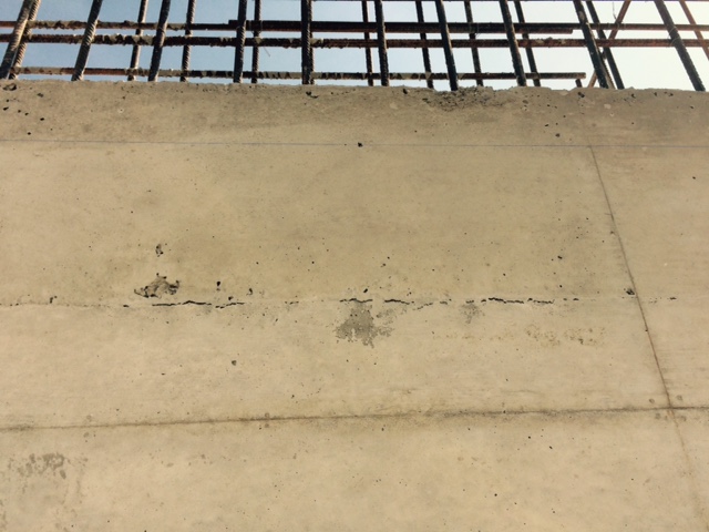
Here are some photos as requested. I must add that although this abutment will be black jacked (bitumen cover) and buried it was intended to look exactly like the finished bridge…we have some work to do!
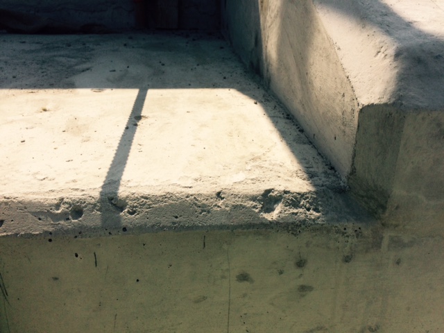
The kicker should simply look like a line joint
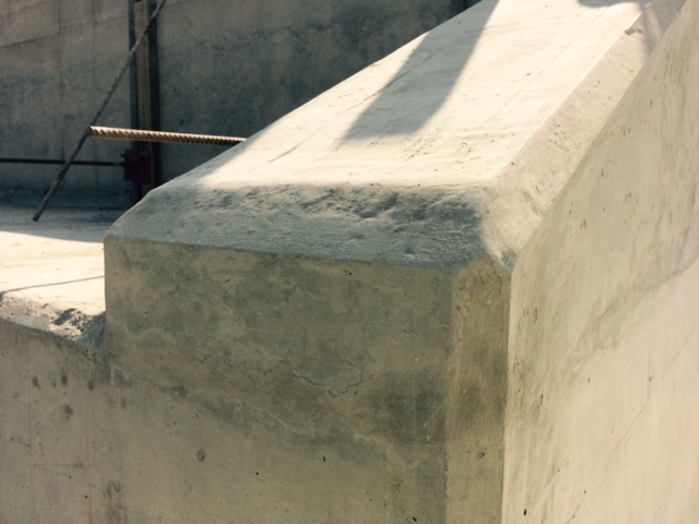
The wing wall has had to be built up. This will not have the durability it should. If you look closely you can see aggregate viable on the top face.

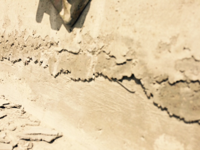
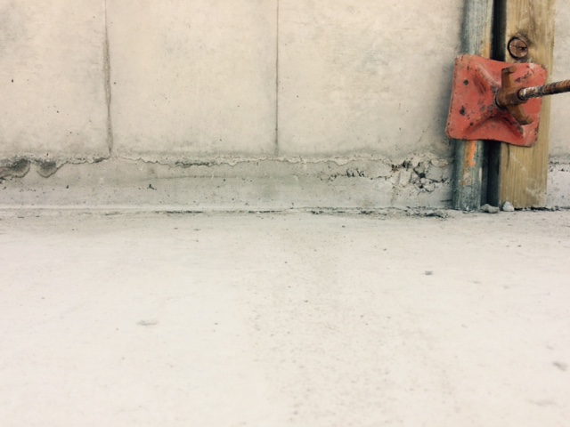
Staining, we’re not sure why…has anyone had anything similar? I am conducting trails in a couple of weeks to try out different formwork materials
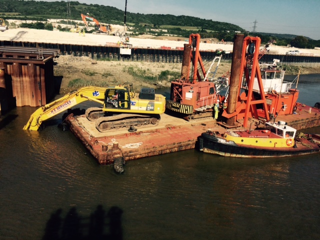
In other news, we hit an obstruction in the river and had to bring in a spud barge with 45tn machine. It proved to be a great spectator sport but not much work was done on site whilst it was here.
Site Two Fifty One – Concrete strength and Waterproofing
Site Two Fifty One – Concrete strength and Waterproofing
A set of cubes for each capping beam pour is taken. BS EN 206 states that any individual 28 day result should be no less than characteristic strength- 4N/mm² and a rolling set of 3 should have a mean less than characteristic strength+ 4N/mm². This means 46N/mm² or 54N/mm². Recent results put it near to the 54 N/mm² limit.
However, after some discussion, the aim now is to use the 56 day results to confirm compliance.
The capping beam cube results have also come back with the piling concrete results. Their mix uses a 50:50 proportion of Portland cement to Ground Granulated Blastfurnace Slag which brings a faster strength gain up to 28 days compared to my mix of a higher (70%) GGBS quantity.
Between 28 days and 56 days there should be more strength gain of the higher GGBS proportion concrete. Although the 56 day strength of the 70% GGBS will be lower overall, there is more gain of strength later on, than that of the Portland cement: GGBS 50:50 mix.
More eloquently:
“Typically a CEM I concrete will achieve about 75% of its 28-day strength at seven days, with a small increase of 5–10% between 28 and 90 days.
At 70% GGBS, the seven-day strength would be typically around 40–50% of the 28-day strength, with a continued strength gain of 15–30% from 28 to 90 days.”
Reference: Cementitious Materials – The effect of GGBS, fly ash, silica fume and limestone fines on the properties of concrete.
So what and who cares?
Faster strength gains (found with higher Portland cement content) = higher heat of hydration = more likelihood of cracking in deeper members. Therefore reducing cement to GGBS content, as long as the eventual strength is of that required (50N/mm² in my case), helps reduce cracking. Who cares? – People who construct below the watertable – me and my project!
Waterproofing
Reflecting on Guz’s comments on the cost of injection grouting cracks to improve the waterproofness of concrete, I am at the pre-pour stage.
We are using a hydrophilic (absorbs water over time) material to form a watertight joint between the top of the piles and the base of the capping beam.
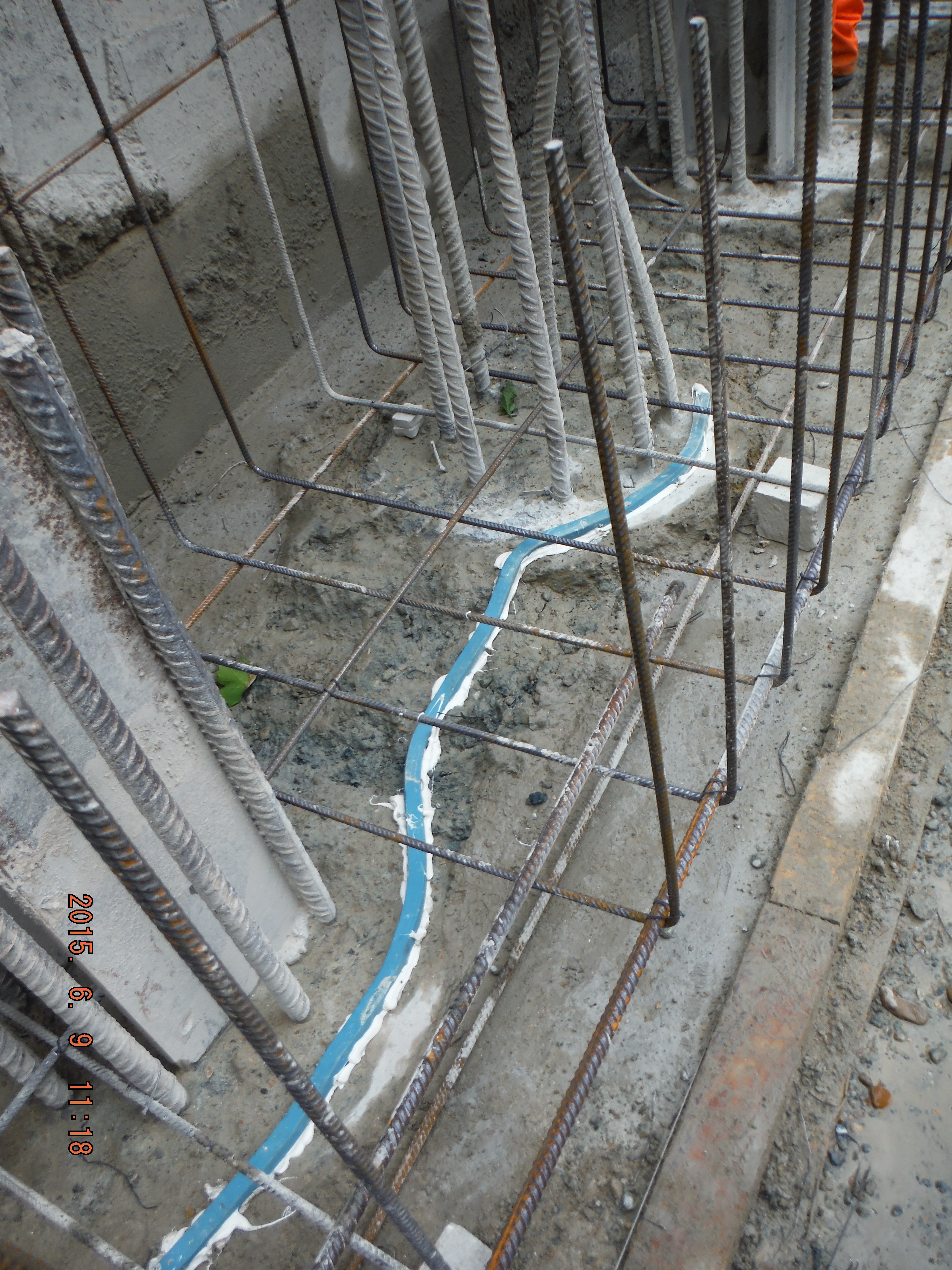
Hydrophilic strip laid along length of secant piles within “waterproof” section.
Line of hydrophilic strip.
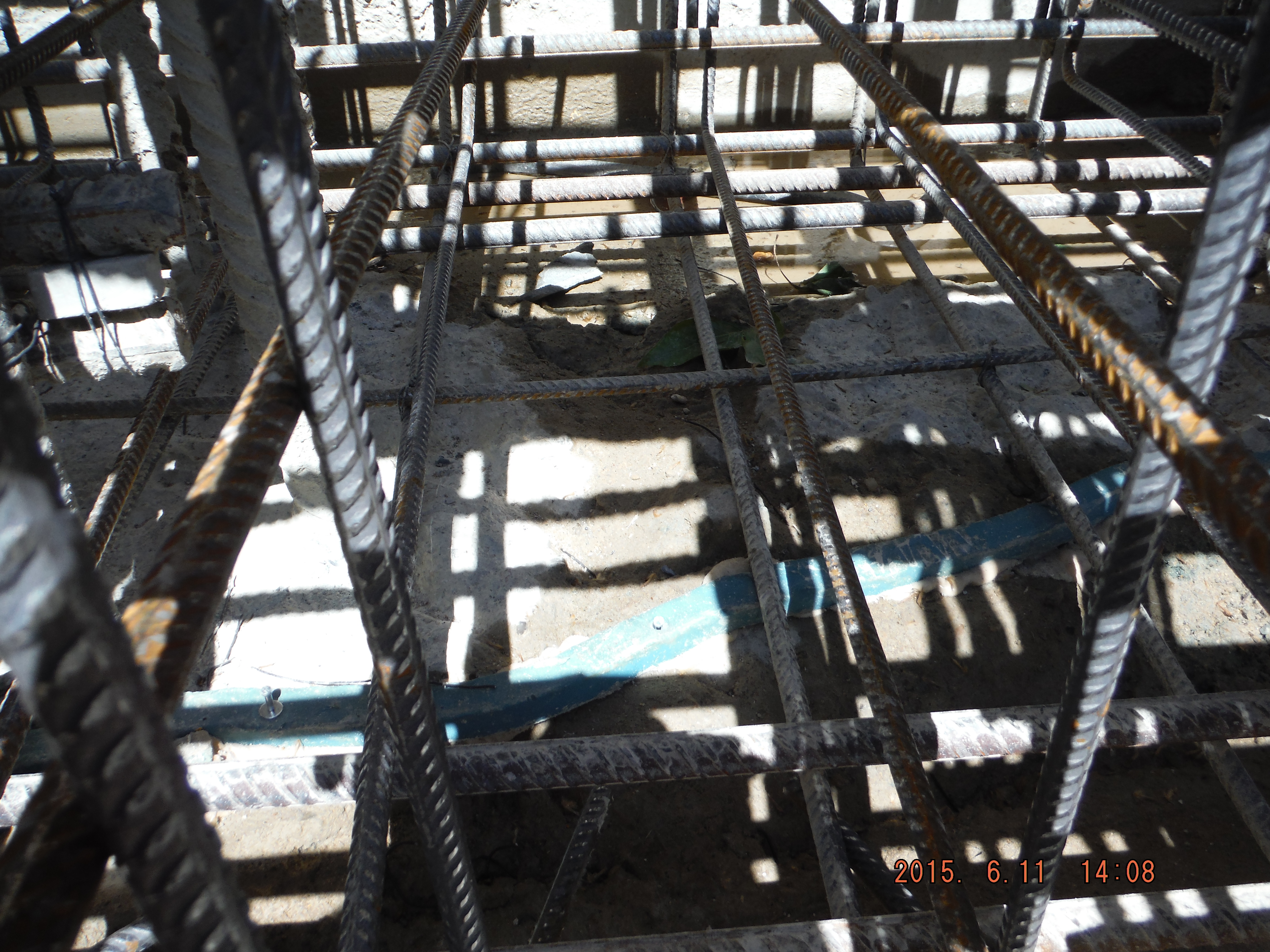
Hydrophilic strip fastened around king posts.
Thoughts.
The advantage of this system is that the joint between the surface of the piles and the bottom of the capping beam will not provide a path for water to pass along.
However, there are fairly significant reality issues with this.
- The piles have been broken to cut off level using breakers – therefore the surface is overly rough and uneven (beyond the mechanical interlock required for a structural joint).
- In the instance of an uneven surface a mastic beading is to be used to sit the hydrophilic strip onto. This is then supposed to be nailed to the piles. Issues here are using masonry nails has safety issues – they fly out and hit people, the nails also provide a water path.
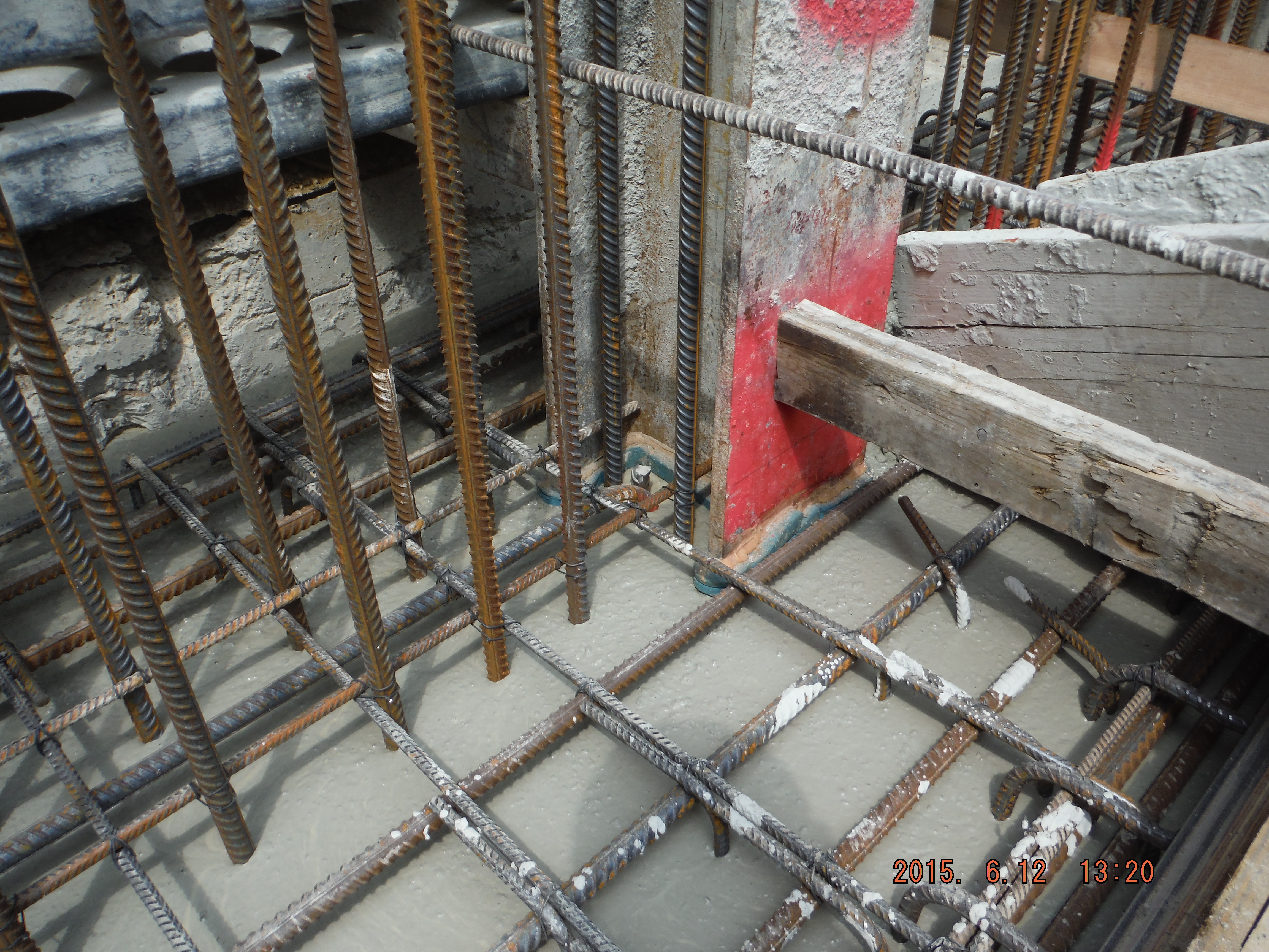
- The reinforcement cage needs to be installed after the hydrophilic strip has been laid. Therefore during the installation of the cage great care has to be taken to avoid standing on the strip.
Waterproof concrete
Finally, and I will only touch on this, we are using waterproof concrete to ensure water does not pass through the capping beam in certain areas. The Grace (company supplying waterproof admixture) datasheet provides a comparison of permeability of the control concrete compared to the waterproof concrete as follows:
Control: 6.90 x 10⁻¹⁴ ms–1
Waterproof: 1.28 x 10⁻¹⁴ ms–1
This translates that in 10,000 years the waterproof concrete might have water penetration of 4mm compared to control concrete of 21mm. Last time I checked, design life of buildings was somewhat less. When identifying risks – this (concrete permeability) is not one of them.
Conclusion
More important are the joint preparation, crack control – through mix design and curing methods and vibration to reduce porosity.

Capping Beam concrete pour with waterproof concrete.
Lessons learnt
Introduction
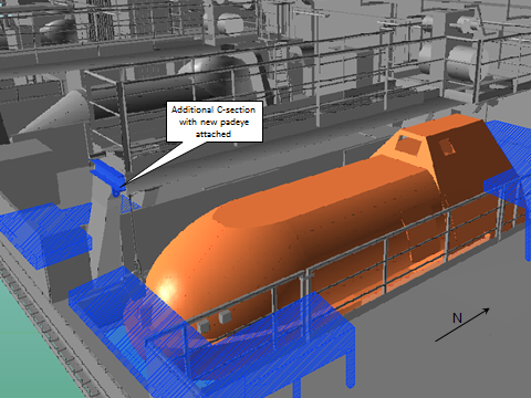
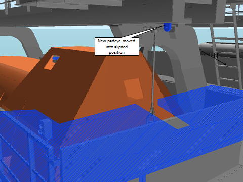
A few years ago a number of lifeboats were upgraded to take into account the increased size of the modern platform worker, which resulted in slightly longer lifeboats. The lifeboats are permanently suspended by the winch lines but require additional pendants and padeyes to temporarily hold the lifeboat when maintenance is carried out on the winching gear. Due to the increased weight and the misalignment of the padeye and maintenance fastening location (due to increased length) it was identified that new padeyes would be required.
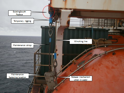
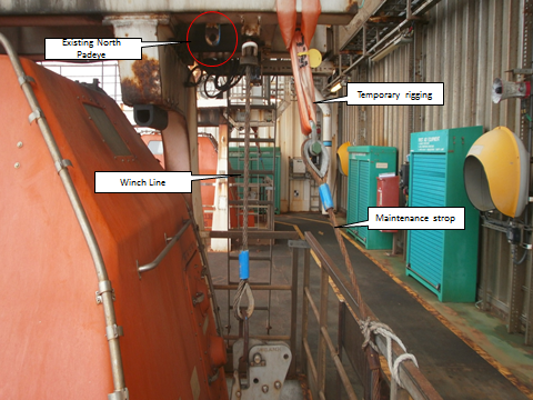
Solution
Quite simply, cut and grind existing padeyes off and weld on new padeyes in adjusted locations. A fairly straight forward job? Nothing is ever that straight forward in an offshore industry!
Who’s who
WGPSN – Engineering Service Provider who are contracted to deliver the project
CAPE – Scaffolding contractors
Sparrow – Lifting contractors
Lloyds Register – Independent Verification Body
Issues
Following a constructability review the following key points were identified.
- Confirmation of the test load for each of the padeyes.
Non-destructive Testing (NDT) is carried out on all padeyes to ensure they are fit for purpose, the question is how much do you test them? Going into the meeting the plan was for a test load of 8.5Te on each padeye, which accounts for a lifeboat tare weight of 4685Kg, 10 pax at 98Kg each and a Safety Factor of 1.5. The gentlemen from Lloyds, who act as an independent verification body, questioned how these figure came about and it could be easy to understand why they would ask that. The tare weight is 4685Kg but is held by two anchor points, so why not half? During maintenance you would only expect 3 pax to be involved so why 10? The industry standard for a safety factor is 2.2 or 2.5 depending on the application, so why 1.5? All very good points and the answer was simple. That is what Lloyds agreed to (told us) at the last constructability review. Unfortunately the individual who told us that was not at this meeting due to being on holiday, so nothing could be agreed there and then.
- Serviceability of the Lifeboat during the offshore execute phase.
Removing the lifeboat from service would impact the number of pax allowed on the installation and would therefore affect a whole host of other activities planned at the same time, so it was important that the lifeboat remains in service throughout where ever possible. Going into the meeting, it was understood that it would be ok; difficult but doable in terms of scaffolding arrangement, protective screens for welding etc. A concern was raised by the construction team in that the job could not be executed without taking the lifeboat out of service, so why had we assumed it would be ok? Again a simple answer; because that was the opinion of the construction representative who attended the previous meeting; that individual has since moved on.
Lessons Learnt
- Continuity is key. Where at all possible maintain key personalities throughout a project in order to help understand decisions made earlier on in the project. Given the recent and still ongoing job losses and efficiency drives in both BP and WGPSN I’m not surprised this has happened. I know I’m not the first person to mention this, and believe it was Angela who made a comment that after 6 months, she was the only person on a project who had been there at the beginning.
- Clear and accurate record of decisions. Whenever key decisions are made make sure it is clearly and correctly documented with any supporting information. The only evidence I had of the test load was in typed handover notes from the previous SPA. If continuity cannot be achieved then this becomes even more vital.
Looking Forward
These issues will cause a delay. Not to the execution offshore phase, as that is in Q2 2016, but certainly to the issue of key deliverables required for offshore execution. Not a concern but if the time lines were shorter then it well could have been. More work now needs to be done to clarify these points and of course man hours means increased costs. It might surprise some of you (or maybe not) that the current budget for this (one might say simple) project is (currently) circa £180k.
Oz PCH – Pipe sizing issues leading to serious commercial implications…
Back in Oct 14 correspondence from NDY (Design Consultants) to Fredon (Mech Installation Subcontractor) raised an issue and posed an RFI regarding both Hot & Chilled water schematics. The RFI asked confirmation that all pipework had been sized and the network designed in accordance with a maximum velocity of 2.5 m/s and maximum pressure loss of 400 Pa/m. Fredon’s reply was yes it had.
In Jan 15 a meeting was held between JHG, NDY and Fredon which highlighted some issues with pipe sizing as referred to above.
In Feb 15, JHG with Cundall (commissioning consultants) conducted a review of all pipework sizing across the project. They found a number of incorrectly sized pipe sections which, although were within the acceptable velocity limits resulted in pressure losses exceeding the maximum 400 Pa/m. These were marked up and sent to Fredon to address asking that they carry out a review to ensure the issues were resolved as soon as possible. In addition it was determined there were also a number of commissioning stations missing (also marked up on dwgs) thus potentially jeopardising the ability to correctly commission the system in accordance with the CIBSE recommendations.
Fredon’s response was they had to change a number of pipe routes due to AHUs and Fan Coil Units moving location in order to make the plantrooms work and all other installed pipework was as per the design schematics from NDY; which didn’t state the 2.5 m/s or 400 Pa/m maximums.
It transpired that NDY did in fact omit the maximum values from their designs, however contractually Fredon don’t have a leg to stand on as all written sub-contracts state that subcontractors are offered the opportunity to review the Client’s Technical Brief and all works carried out must comply with that brief irrespective of any design requirements from the design consultancy (NDY). This case being a perfect example of why subcontractors are offered this opportunity so they can follow the Client’s intent. So, did Fredon view the brief? Of course not! Well not until the preverbal hit the fan.
The exact requirement from the Client’s Technical Brief states:
…pipework shall be designed with a maximum water velocity of 2.5 m/s and maximum friction loss of 400 Pa/m.
Why are 2.5m/s and 400 Pa/m the maximums? Higher velocities create more noise through vibration and higher pressure losses create inefficiencies in running the system and results in increased running costs.
This issue was presented to me on 19 May 15 by my LM to double check that pipe sizing runs in a couple of plantrooms were installed in accordance with the requirements above. There was a fair amount of digging into records etc to get a good understanding of the problem and also waiting for reviews from both NDY and Fredon before the whole picture became clear, hence the date of this blog.
Method
I was given two plantroom schematics; PR 6 (Heating Hot Water) and PR 5 (Chilled Water). Both had the pipe runs annotated with the pipe diameter (mm), flow rate (l/s) and velocity (m/s). Establishing if the velocity was in limits was easy as it was annotated on the dwg but I had to calculate the pressure drop (Pa/m).
To do this I turned straight to CIBSE Guide C Reference Data. I was given a steer that there was a CIBSE version available called the CIBSE Student Guide. This is basically a condensed version of all the most popular and more widely used parts of all CIBSE Guides rolled into one. So I looked here first and found the section with tables on flow of fluids in pipes and ducts. Looking at the Hot Water system first meant selecting the correct temperature (75ºC) and pipe material (copper).
I then simply read off Table C4.13 the closest diameter pipe size to what the drawing said e.g. Ø 65 mm on the dwg would be 67 mm from the table.

Table C4.13 CIBSE Guide C Reference Data.
Agreed there is a 2mm difference and yes I could simply interpolate between 54 mm and 67 mm from the table but for a quick and dirty answer this wasn’t necessary. Equally if I were to interpolate then I may as well get an even more accurate answer by using the mathematical method. Therefore using the various equations required from the main CIBSE Guide C doc, the mathematical solution is thus:
So it turns out word press won’t allow pasting of equations from word – rubbish!
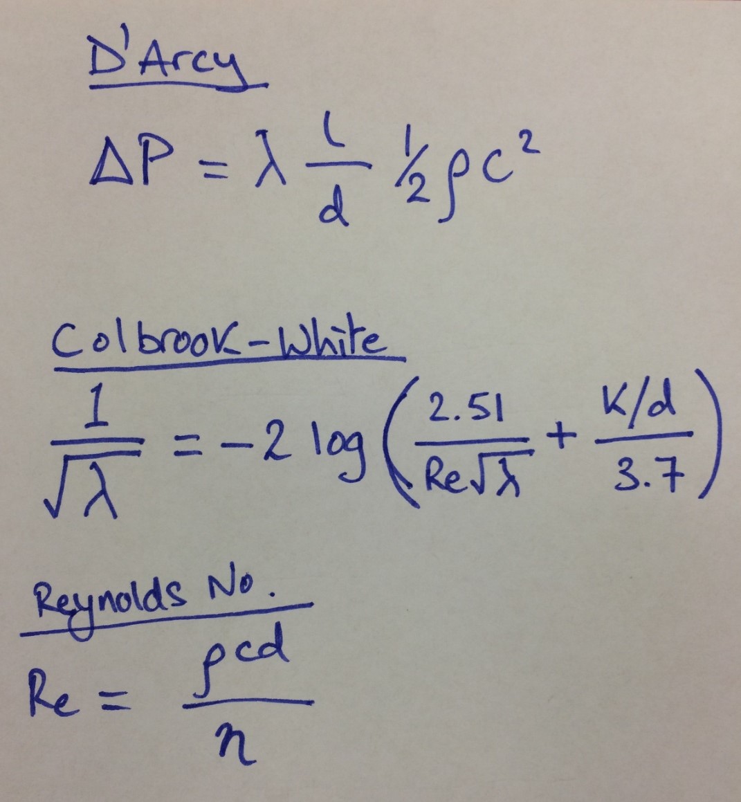
The D’Arcy equation for pressure loss due to friction:
The friction factor, λ (for turbulent flow) was obtained mathematically from the Colbrook-White equation which is more accurate than using the Moody chart:
Reynolds number:
Equations for above.
Relative roughness = k/d
To determine the values of ρ (kg/m3), η (10-6 kg/m/s), and v (10-6 m2/s) properties of water I used Table 4.A1.1 from CIBSE but wanted the temp at 75ºC. So therefore some interpolation was required:
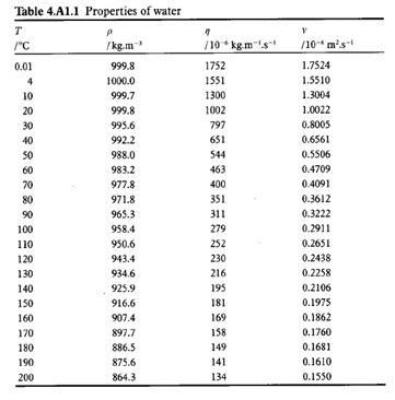
Table 4.A1.1 from CIBSE.
Using a handy interpolation equation:
d = d1 + (d2 – d1) (g – g1) / (g2 – g1)
Calculations
See below hand calculation sheet.
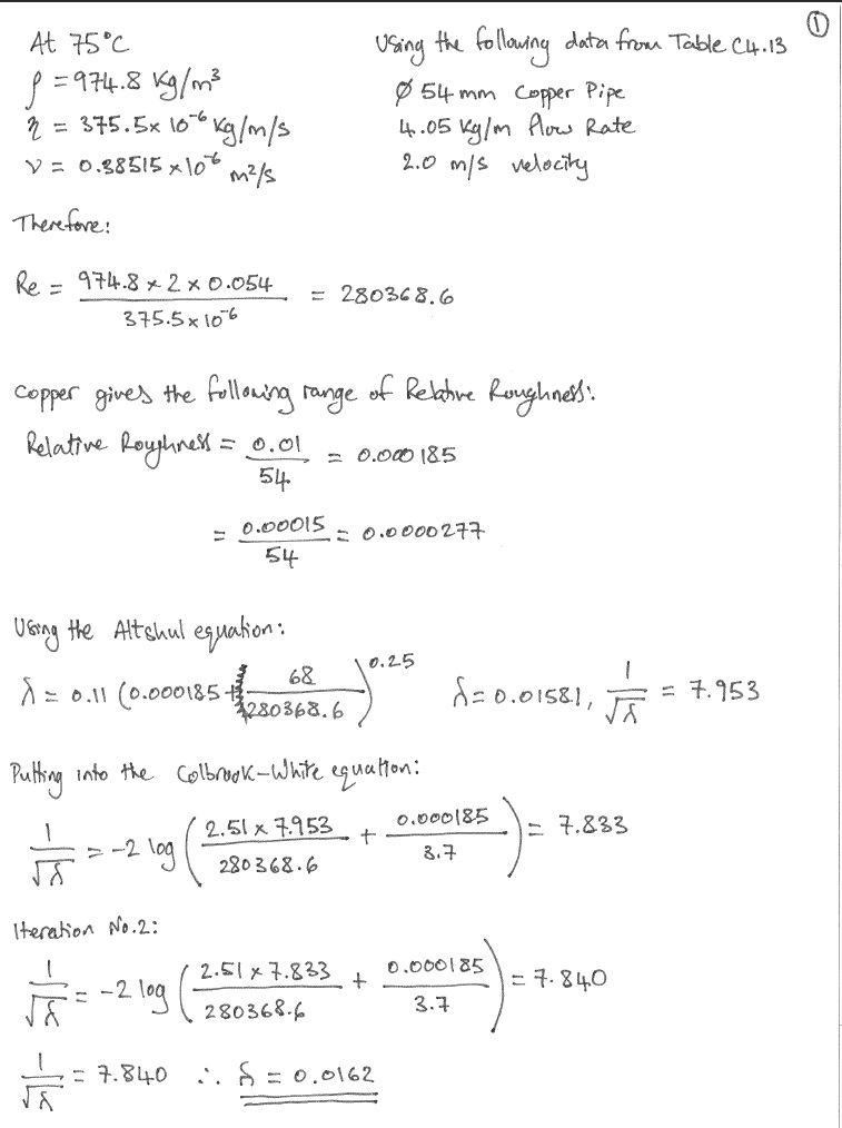
Hand Calculations – Sheet 1 of 3.
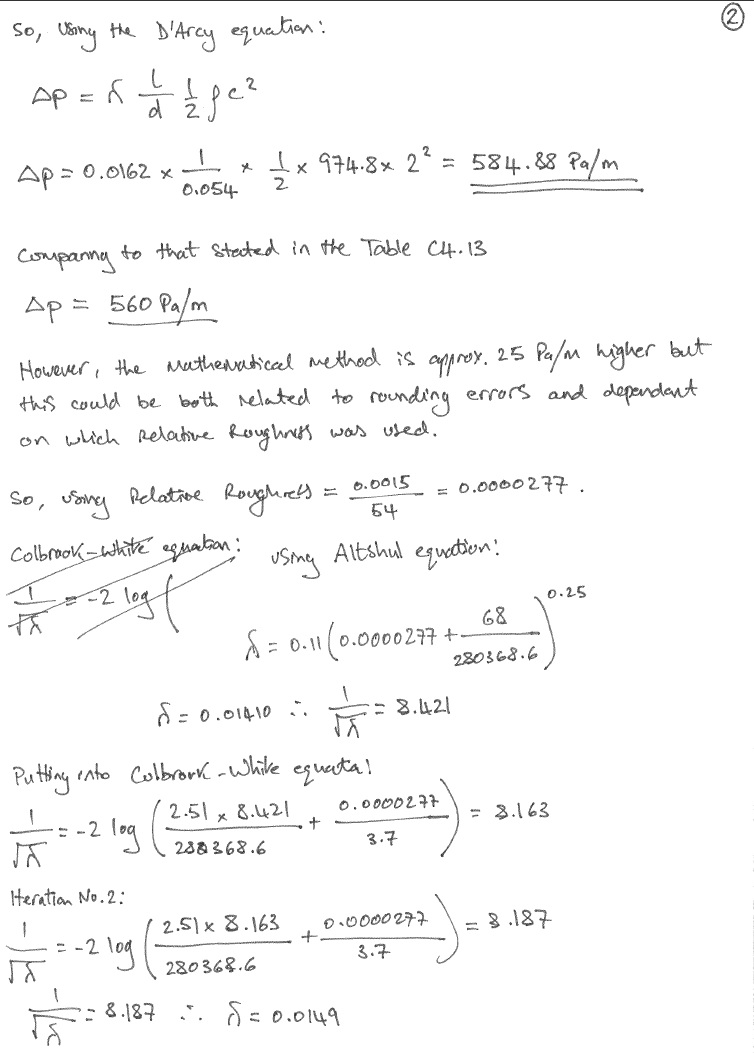
Hand Calculations – Sheet 2 of 3.
Hand Calculations – Sheet 3 of 3.
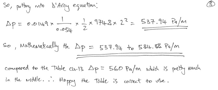
Therefore, if the schematic shows; Copper Ø 65 mm, at a flow rate of 6.63 l/s and velocity of 2.3 m/s the AIRAH charts gives a ∆P = 575 Pa/m.
Mathematically using the same process as above ∆P = 555 to 872 Pa/m.
The closest on CIBSE Table C4.13 is Copper Ø 67 mm, at a flow rate of 6.65 l/s and velocity between 2 – 3 m/s which gives a ∆P = 480 Pa/m.
Mathematically using the same process as above ∆P = 535 Pa/m.
Findings
As a result of checking other PR pipe networks it was found that a number of pipe sections were over the max 400 Pa/m. Therefore JHG issued a Non Compliance Report (NCR) (the highest quality control level of report that gets recorded against the project) stating that we conducted a review of Fredon’s pipework and found as stated above. Both Fredon and NDY went away and also conducted a review resulting in another mtg to discuss the findings along with the contractual implications.
In the meantime I wanted to double check the material for the pipework in PR5 as the pipe equipment in BIM said it was steel yet all other plantrooms used copper. On inspection there was good and bad news; the bad news was I couldn’t find the pipework (only the main 250mm dia supply coming up the riser) but the good news (related to the bad) was it hadn’t been installed yet hence no pipework found. This meant that any pipe sections diameters could be changed thus avoiding an expensive rip-out and re-install.
Steel is cheaper to purchase and more wear resistant than copper however, copper is easier to install (brazing method vs welding of steel) and thus saves time and therefore cost (making copper cheaper overall).
The outcome of this mtg was both NDY and Fredon used pipe sizing charts from the Australian Institute of Refrigeration, Air-conditioning and Heating (AIRAH) Technical Handbook to select their pipes but we couldn’t figure out whey on the same schematic (same velocity and pipe size) they were getting different pressure losses.
We asked Fredon to send us their AIRAH charts and after further investigation we found the error.
NDY say they designed all pipework using steel however their design brief for piping material talks about various materials but doesn’t actually state a design material. Also, there is no mention of material type on any of their schematics. The design brief states:
Pipe sizing on the drawings for pipe fluid velocity, friction rate and pump head calculation are the standard method of size identification for that material e.g. mild steel pipe – DN (nominal bore); copper pipe OD.
Where alternative pipe materials are scheduled as acceptable, the nominal bore of the alternative shall be equal to or greater than that of the nominated mild steel pipe DN.
Fredon made the value engineering decision to install copper and therefore should have understood that when comparing steel and copper the industry norm is to refer to them using their ‘nominal size’. As quoted from the Australian Standard (AS 1074 – 1989)
‘1.3.5 Nominal size (DN) — a numerical designation of size which is common to all components in a piping system other than components designated by outside diameters or by thread size. It is a convenient round number for reference purposes and is only loosely related to manufacturing dimensions’.
However, they should have also realised that steel’s actual internal dia is larger than the stated nominal size compared to copper’s actual internal dia which is smaller than the stated nominal size (copper’s nominal dia is almost akin to the OD (external dia)). This can be seen from the internal pipe sizing table at Table 4.2 CIBSE Guide C and the AIRAH charts below. This comparison is the same for both the UK and Australian construction industries, however, AIRAH present their charts with both materials having the same nominal internal dia and this is what caused the confusion resulting in the errors. NDY designed the pipe networks using steel pipe (e.g. 32mm dia gives 400 Pa/m) but when Fredon changed material to copper they simply used the same 32mm dia pipe. But a copper 32mm nominal pipe has an actual internal dia of 29.26mm which is smaller than the steel pipe’s nominal dia of 32mm (actual internal dia of 36mm) hence over a 6mm dia difference which creates higher pressure losses.
What Fredon should have done was compare the two AIRAH charts by material and therefore upsized the nominal dia of copper pipe to 40mm giving an internal dia of 35.61mm therefore meeting the design brief and thus ensuring a similar pressure loss to that of steel – not exceeding 400 Pa/m.
The charts below show the pressure loss of 82ºC water in both medium steel and copper pipe and compare three different pipe sizes to show the effect the material has on pressure loss.
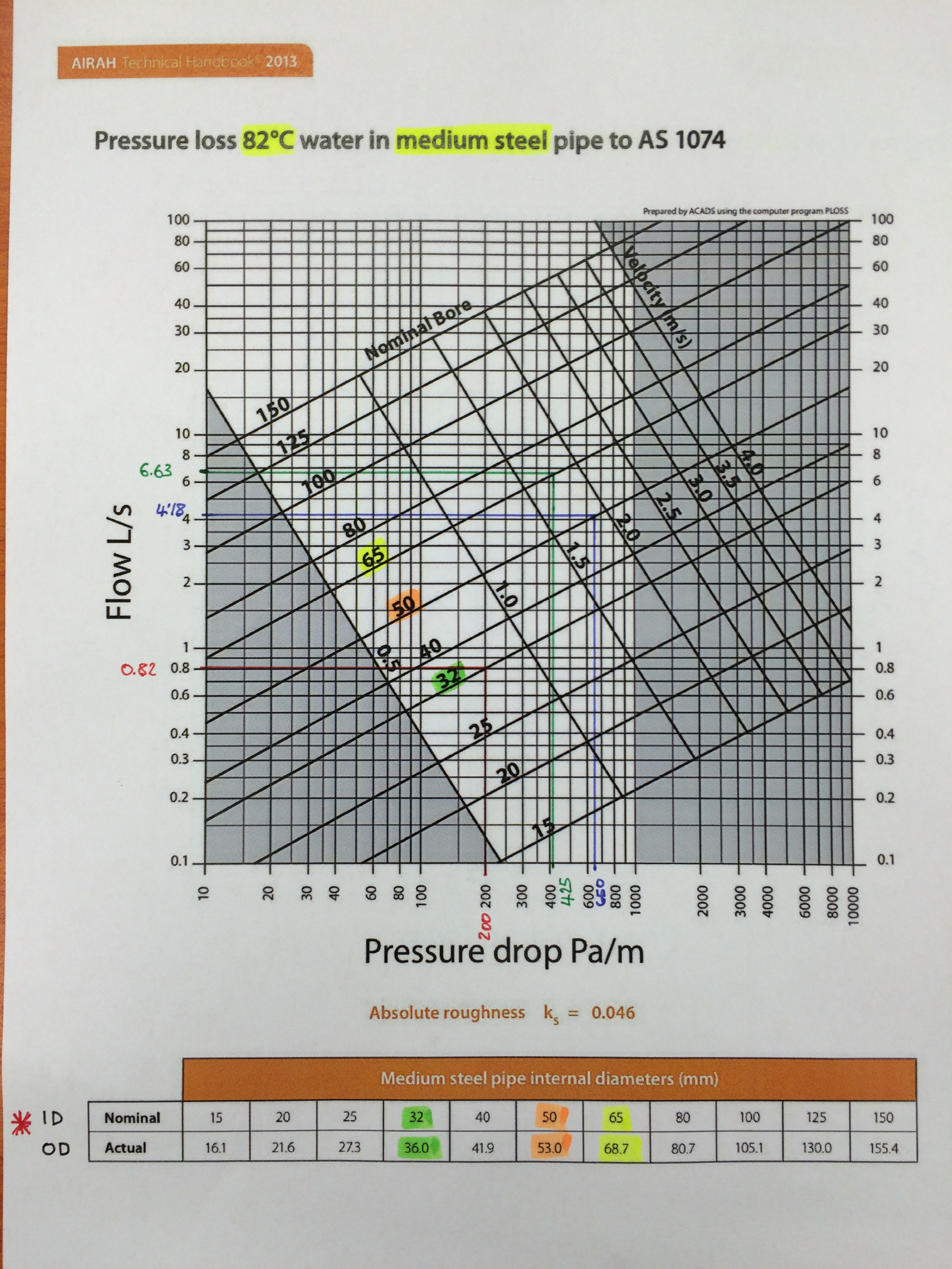
AIRAH Medium Steel Pipe.
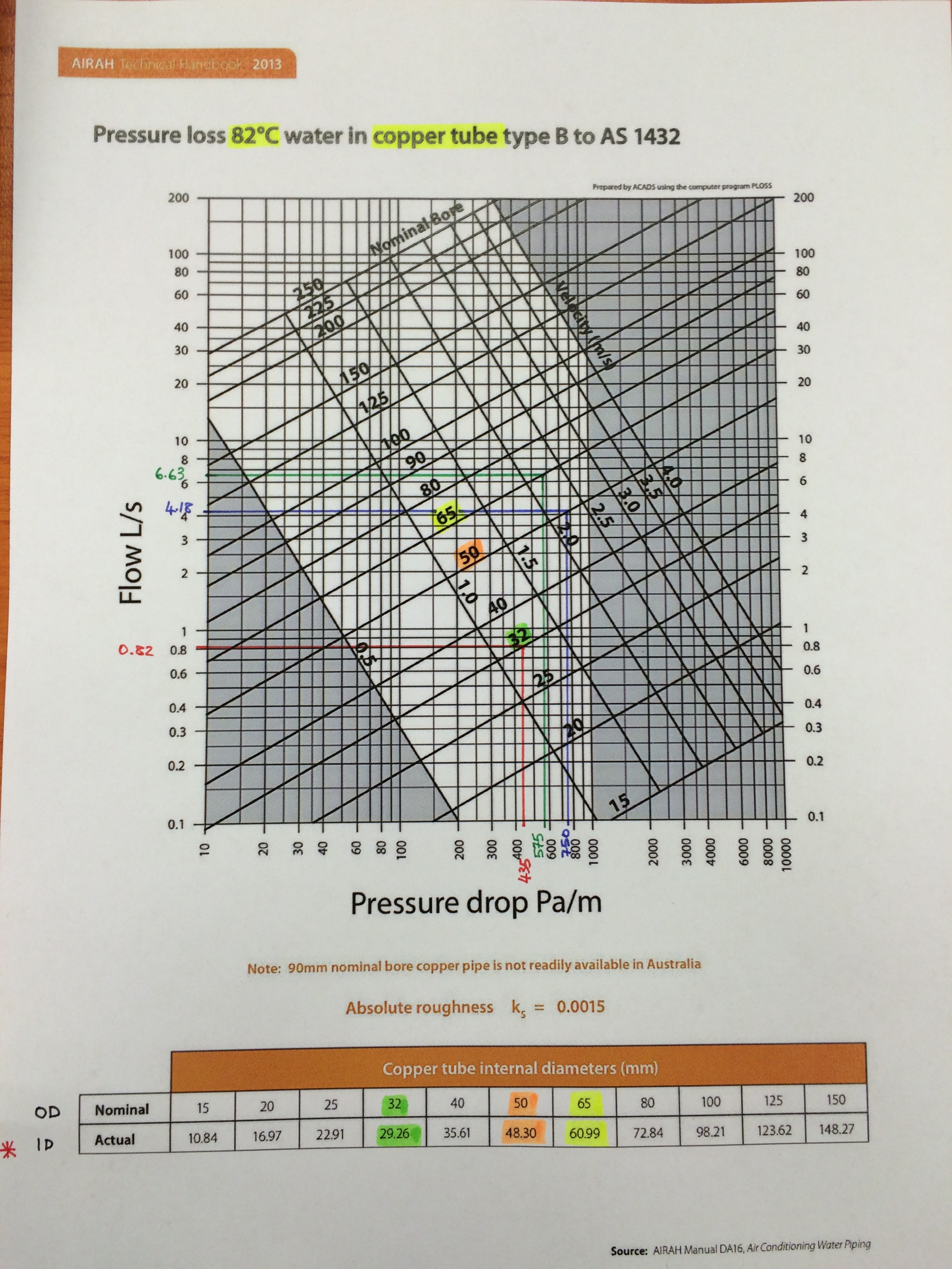
AIRAH Copper Pipe.
So you can see, assuming that you can change from steel to copper pipe (without identifying the nomenclature change AIRAH uses) is incorrect and results in under sizing your pipes thus increasing pressure losses.
This is why the CIBSE Guides and the UK construction industry, on the whole, use different standard pipe sizes for different materials to avoid this confusion. The table below is an extract from the CIBSE Guide C.

Table 4.2 CIBSE Guide C.
So What?
Technically, why does AIRAH refer to both steel and copper piping on their charts using the same nominal dia knowing the actual internal dia is very different?
Why don’t they use a different nominal dimension for say copper like they do in the UK and then have charts that reflect this like Table C4.13 from CIBSE Guide C?
The only dia that actually affects the flow rate and thus pressure losses is the internal dia (the A in Q = A x V), the nominal/OD and wall thickness matter not.
Commercially, JHG need to establish between NDY and Fredon who is the cause of the issue that means JHG currently don’t meet the Client’s brief. They need to establish the extent of what is required to resolve the issue and commercially who will pay for it. When taking into consideration the increased running costs over the lifecycle of the system with pressure losses above 400 Pa/m vs the project resolution (measured by cost and delay to project completion) of ripping out and re-installing new pipework, it could be argued that the latter would be much more expensive. Additionally, Fredon say the pipe runs that are above 400 Pa/m (in most instances around 550 Pa/m) are relatively short and thus the extra cost associated to the inefficiency would be negligible. In which case Fredon would rather pay the yearly additional cost for the lifecycle of the system rather than rip out and start again. Clearly not the point and goes against the Client’s brief and more importantly trying to achieve a system with the best possible energy efficiency thus helping to reduce carbon emissions.
Resolution Options
More importantly, to reduce delays, the resolution is the primary focus. There are two viable proposal options for the Project Director and the Client to discuss: both require proving the extent of the problem and then either; order Fredon to replace all incorrect pipework in PR’s 1 and 2 only (index run) and then request dispensation for the remaining incorrect pipework (doubtful); or order Fredon to replace all incorrect pipework throughout the building. Both have commercial and time implications but the second option could potentially bankrupt Fredon. Therefore, a key factor both JHG and the Client need to seriously consider in order to avoid unnecessary delays are the potential second and third order effects of having to get a different mechanical subcontractor to complete the works (with respect to meeting the project’s practical completion deadline). Either way JHG will still carry the problem to solve on the Client’s behalf.
Conclusions
The above findings don’t resolve the issue but will aid in leading to the correct commercial outcome. Fredon say they were following the NDY design schematics in which case 32mm pipe is correct but only if the schematic doesn’t state steel pipe. If the schematics do then Fredon, deciding to use copper, should have up-sized to 40mm as described above. So, JHG need to establish the material stated on NDY’s schematics in order to identify the faulty party. The truth is that neither NDY nor Fredon are squeaky clean and so commercially they may both end up paying for the resolution.
To resolve the issue JHG are looking primarily at replacing only the incorrect pipework on the index run (PRs 1 and 2). Through Fredon’s as-built drawings they should be able to establish which pipe runs are over 400 Pa/m and by how much and then estimate the extent of time and cost to replace them. Both of which JHG and the Client have a vested interest in keeping to a minimum.
The meeting this coming Monday will be very interesting and I will blog a subsequent update on the resolution and commercial aspects as they come to light.
Recommendations
It could be recommended that AIRAH change their pipe sizing charts to reflect those of the UK construction industry like those produced by CIBSE.
In other news
My collection of sports equipment is steadily growing so I have found a new hobby to help pay for it!
There’s snorkelling gear and a kite surfing training kite on the shelf too!

That’s my winnings!
AMAROO MAIN SEWER PROJECT – 260,000 turds per day!
I have been in Melbourne for almost 4 weeks now and have spent 3 of them finding my feet in the JHG head office and 1 of them trying to work out how to post on the blog. The project I find myself on has not yet hit site and will not do so for another few weeks. Not great considering time on site will be shortened, but it has given me the opportunity to interrogate my captive audience in the office for project information to put AER1 together.
The best way to describe my initial few weeks would be akin to being the new dog in a well established pack. We are most definitely still at the backside sniffing stage. Picture Daz in the middle of the room being circled by dingoes all having a whiff.
Week one was great; I dented my work vehicle reversing into a concrete column – first impressions and all that. Today I got a double combo traffic fine for following Mr Satnav onto a toll road, not paying and trying to play the tourist card (epic fail). The first incident report for the project belongs to yours truly. Explaining that to my project manager was interesting (he is a mountain of a man from Glasgow with hands like baseball mitts – not one you want to annoy).
Anyway, no-one died and the project must go on, or start at least.
I have done this a bit back-to-front in order to submit AER1 in time. So instead of a blog feeding an AER, my AER will write this blog…
My role is as Project Engineer for the Amaroo Main Sewer Project, located roughly 30km north of the Melbourne CBD (central business district). Yarra Valley Water (YVW) is the largest of Melbourne’s three water corporations and services the Northern growth corridor which includes the Amaroo Main Sewer Project. The Victoria State government’s Metropolitan Planning Authority predicts that this corridor will grow to accommodate a population of 260,000 people. There are currently no existing major sewers (or wag bags) in the regions where this growth is expected to occur and the delivery of the Amaroo Main Sewer will ensure sustainability for the development.
YVW intends to construct a new 7.8km long main sewer from North of Donnybrook Road to the existing Kalkallo Recycled Water Treatment Plant in Craigieburn. The main sewer is proposed to have an internal diameter of 1,575mm and be founded at depths ranging between 6m and 14m. YVW has requested that the John Holland Group Pty Ltd (JHG) tender for the Amaroo Main Sewer Project. In turn, JHG has requested that GHD Pty Ltd (GHD) provide a proposal for the temporary works design services for the project.
The Project comprises a trunk sewer, provision for 12 future sewers and 1 connection to an existing YVW branch sewer. This is to accommodate development of the land between Craigieburn and Donnybrook in the future. All sewers are required to have a 100 year life, a smooth internal surface and be installed as per the drawings to ensure gravity fed hydraulic performance requirements are met. The proximity of entry chambers will vary between 284m and 695m, with an average of 502m. They will have internal diameters ranging between 3.2m and 6.0m, with depths from 5.1m to 19.2m. All manholes are required to allow sufficient space to meet operational and maintenance access requirements for the sewer. The delivered article will have no staged access. To reduce the risk of incidents caused by human fatigue, maintenance personnel wearing sewer gear will be lowered into and lifted out of the manholes by means of a Davit Arm. Checking the sewers (up to 695m in length) will continue to be done conventionally.
The head contract is an AS4000-1997 Construction Contract (Modified) between The Client (Yarra Valley Water Corporation) and the Contractor (John Holland Pty Ltd). It is a traditional lump sum contract of $84,179,360.58 AUD – construct only. The lump sum was derived by JHG using a combination of first principles and experience. They benchmarked this project against their previous recent tunnelling project in Woolloongabba. With similar ground conditions and TBMs (tunnel boring machines); JHG used 8m per day tunnelling per TBM as their benchmark when creating their lump sum amount. In order to be able to provide a lump sum, JHG had to know what their pipe suppliers would price at. JHG conducted early negotiations with two prominent competitors – I-Plex and Hobas. After establishing the scope of works with zero (or as close to as possible) unknowns, JHG asked both suppliers for their BAFO (best and final offer). This single contract with I-Plex accounts for $60m of the head contract $85m. From this BAFO, JHG submitted their lump sum to YVW. Schedule of rates contracts under variations would include extra tunnelling e.g. if the client was to request JHG to tunnel further, this would be priced per meter tunnelled.
The client has employed a designer (JACOBS) and a Clients Representative (Aurecon). The client is utilising a third party representative to provide technical and commercial expertise i.e. the client is passing the risk to Aurecon. Jacobs have compiled a Geotechnical Data Report (GDR) which has been analysed to produce a Geotechnical Baseline Report (GBR). The purpose of the GBR is to clearly and succinctly communicate the risks associated with the ground (relevant to the project) to the client (a GDR as we know it).
The method of shaft excavation varies along the project corridor. The three southernmost shafts will be constructed conventionally by excavator and hydraulic hammer (without the use of explosives). The remainder will be either drill and blast or open trenching (depth dependant). Varying thicknesses of steel fibre-reinforced shotcrete (with a compressive strength of 40MPa) will be sprayed onto the shaft walls to mitigate the threat of block slip planes and fretting. JHG will employ a geotechnical engineer to map the rock shaft walls to identify possible slip planes. There is an option to use anchor bolts in resin anchors and steel mesh if the shaft walls are assessed to be unstable.
JHG is not following the usual sub-contracting route. Instead, they will use direct works which is unusual for a Main Contractor these days. JHG will carry out WUC using its specialist tunnelling sector. This demonstrates an appetite for risk; showing a willingness to accept the risk for financial gain. When considering their vast experience in tunnelling, it would appear they are suitably placed to make educated decisions on identifying opportunities in the risks.
A selection of sub-contractors are in the process of tendering for work on the project. In evaluating payment, JHG will receive claims for work done by engaged sub-contractors. These claims will be evaluated by comparing the actual work done against the specified task, and then payment made if JHG is satisfied that the sub-contractor has met its contractual obligations. We are not contractually due to start on site until August 2015, however the client is hoping to grant us access to site on 18 June 2015.
So what have I done? The first few days were spent reading the contract, the specification, the GDR and the GBR. Once my insomnia was cured I was responsible for the DBYD (Dial Before You Dig). This organisation operates 24/7 and acts as a single point of contact between us and service providers. I give a location and proposal of works to be carried out in the area, and receive information from all companies with water, electrical, gas or communications assets in the vicinity. It is streamlined process with a rapid turnaround (all companies provided their information within 2 hours). From this data, I have been compiling a risk assessment on the likelihood of damaging any of the abovementioned assets, putting all data on a one-pager for easy access.
Following on from that, I have been putting together tender packages to be sent out to potential sub-contractors. These include the scope of works, the sub-contract or purchase order, the specification and the drawings relevant to their package. I am specifying by outcome, not method, so as to pass the risk to the suppliers. We have accepted enough risk in the tunnelling.
Notably, I have been tasked with securing a package for the drugs and alcohol testing. It goes without saying that I am eyeing out a ‘buckshee’ breathaliser to see what reading (beer-not-drugs) I can score over one of my loose BBQs.
This week will see us wrapping up the tender packages and hopefully get the surveyors on site to start marking up.
Tomorrow morning I will be attending a CHMP meeting, affectionately referred to as a ‘chimp’. Led by the environmental officer, it is a meeting with the local Aboriginal tribe to discuss the proposed works and identify any artefacts of cultural importance. Identified items will be removed and then restored in place once the execution phase is complete. A huge amount of attention is given to environmental issues, and I am preparing myself for some gobsmacking stuff. On the plus side, Merri Creek (which we will be tunnelling through) is a renowned hotspot for Brown Snakes and Tiger Snakes – both of which are pretty much one way tickets to the crematorium. As John said – God picked up everything that could kill you by looking at you, and threw it in Australia. I am currently on the lookout for a fishtank off gumtree to start my collection of these non-friendly drunken beasts.
BBC News Hyperlink
An interesting approach,
http://www.bbc.co.uk/news/resources/idt-3cca82c0-af80-4c3a-8a79-84fda5015115
Fort Indiantown Gap
Fort Indiantown Gap (FtIG) is a U.S. Army post primarily used as the Pennsylvania National Guard Headquarters and main training facility about 25 miles North East of Harrisburg. It is also the location of another project I am involved in/running.

Map showing Fort Indiantown Gap
As part of America’s war on greenhouse gas emissions, or perhaps their fear of other people controlling energy resources, FtIG is converting from a reliance on oil to natural gas as it’s main form of heating energy. This is in common with a lot of other Department of Defense (DoD) sites and is as a result of an executive order issued by the great environmentalist George Bush. From this two questions should spring to mind; the first of which being how old is the executive order, well it’s from 2007. The second possibly has more to do with George Bush’s politics and for that discussion I will have to refer you to the kebab shop in Kingston upon Thames.
Either way, as a result one of the boiler rooms at FtIG requires a replacement of its 2 x heating boilers, domestic hot water boiler, their pumps and most of the pipework within the plant room as well as cleaning the chiller pipework. The existing system was installed in 1975 and has been somewhat tampered with, although not completely refitted it appears so, with a 15 year design life, is on its last legs. Below the diagram shows the as built drawings of the heating and chilled water systems with my annotations for the summer and winter conditions:
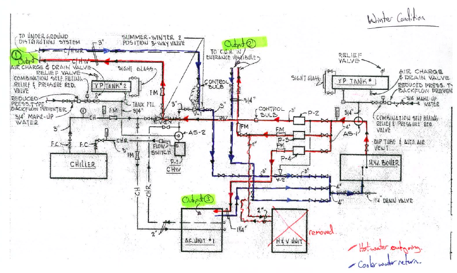
Winter Condition
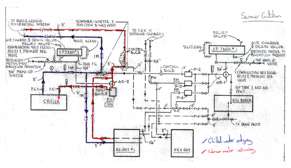
These systems have three outputs, as shown in the winter condition: firstly to the underground pipe network feeding the Variable Air Volume (VAV) terminals in the building with either hot or cold water depending on the season. Secondly, due to the removal of the Heating and Ventilation (H&V) Unit (bottom right) a single unit heater is supplied and thirdly the air conditioning unit within the plant room which supplies ducted air into the building. What is significant about this system is mainly that the first output consists of a single, two pipe system supplying either hot or chilled water. Therefore in the seasons of spring and autumn when the requirement of the system is likely to vary between heating and cooling throughout the course of a day the system will have to cool the water within the pipework before having any effect on the building.
So are we going to fix that, hell no! Currently the design is merely to replace like for like despite there being a reasonably simple solution. This appears to be due to the ’colour of the money’. The money funding this project is only supposed to fund improvements in efficiency rather than improvements in performance.
To see what the actual cost would be I decided to do a calculation, so assuming the 3” pipe is 1km long, the water is of density 1000kg/m3 and would have to be cooled from 80°C to 10°C.
Water Volume in pipes: V=length x π r2 = 1000 x π 0.03752 = 4.42m3
Water Mass in pipes: m = ρV = 1000 x 4.42 = 4420kg
Heat loss required: Q = mCΔT = 4420 x 4.18 x(80 – 10) = 1293MJ
Converted to kWh as that is what electricity is billed in: 1293000/3600 = 359kWh
Assuming the fort pays the same as I do per kWh the cost is 13c/kWh, therefore:
0.13 x 359 = $46.72 per time the system is cooled down. So if this occurs 30 times during each spring and the same each autumn, that is 60 occurrences per year, costing $2,803.
Whilst in ‘calculation mode’ I thought it worth looking at the time it would take to cool the loop down to determine the response of the system. So assuming a 60 ton chiller (from a combination of the drawings and a SWAG):
Power in KW = 3.5 x Power in tons = 3.5 x 60 = 210kW
t = Q/P = 1293000/210 = 6,161s or 1:43
So at the point that the system determines to go from heating to cooling it will take nearly 2 hours for the system to start to have an effect, not ideal on a hot spring day. In payback period terms it is probably in the same region as Mike’s windows. However, like Mike’s windows the system will probably be in position for long past that time period and in the mean time it will produce an enhanced product and save the environment a little, which would surely be good enough reasons on their own. So what, well it seems like a sensible idea to me but I imagine the issue of the funding will be what prevents a logical decision being made. Sadly if we don’t implement something it will be a kick in the teeth for me on competence E3 but hopefully my case here is an element of evidence enough for that!
In other news Jo is now the proud owner of a Maryland State drivers licence. Her test consisted of backing into a parking bay followed by a short cruise around the block completing both left and right turns at four way stops. No traffic lights and she didn’t get above 25mph. Jo was expecting to have to parallel park the car at some point but apparently that was taken out of the test last week because too many people were failing; words fail me!
