Archive
The Splice of Life
Work continues on site at a fairly decent pace and there is much focus on the project interfaces especially now that the Notice to Proceed (NTP) has been given to the third project on the site. There is talk at present about the selected construction methods for the project I am working on with regards to the erection of the structural steelwork. This will form a part of the central atrium and will ultimately be the architectural feature of the whole building. At present the proposal is that as the steel columns are placed they will be tied from the outside of the building until the relevant roof truss section is placed and the element of the frame becomes self supporting. However due to delays on the adjacent project and subsequent efforts to make up the time they now require the space where the ties were supposed to go. This means that either 1. The ‘ties on the outside’ idea will now have to become a ‘struts on the inside’ idea to accommodate work on the façade of the adjacent project. 2. Shift work. This is still very much a work in progress.
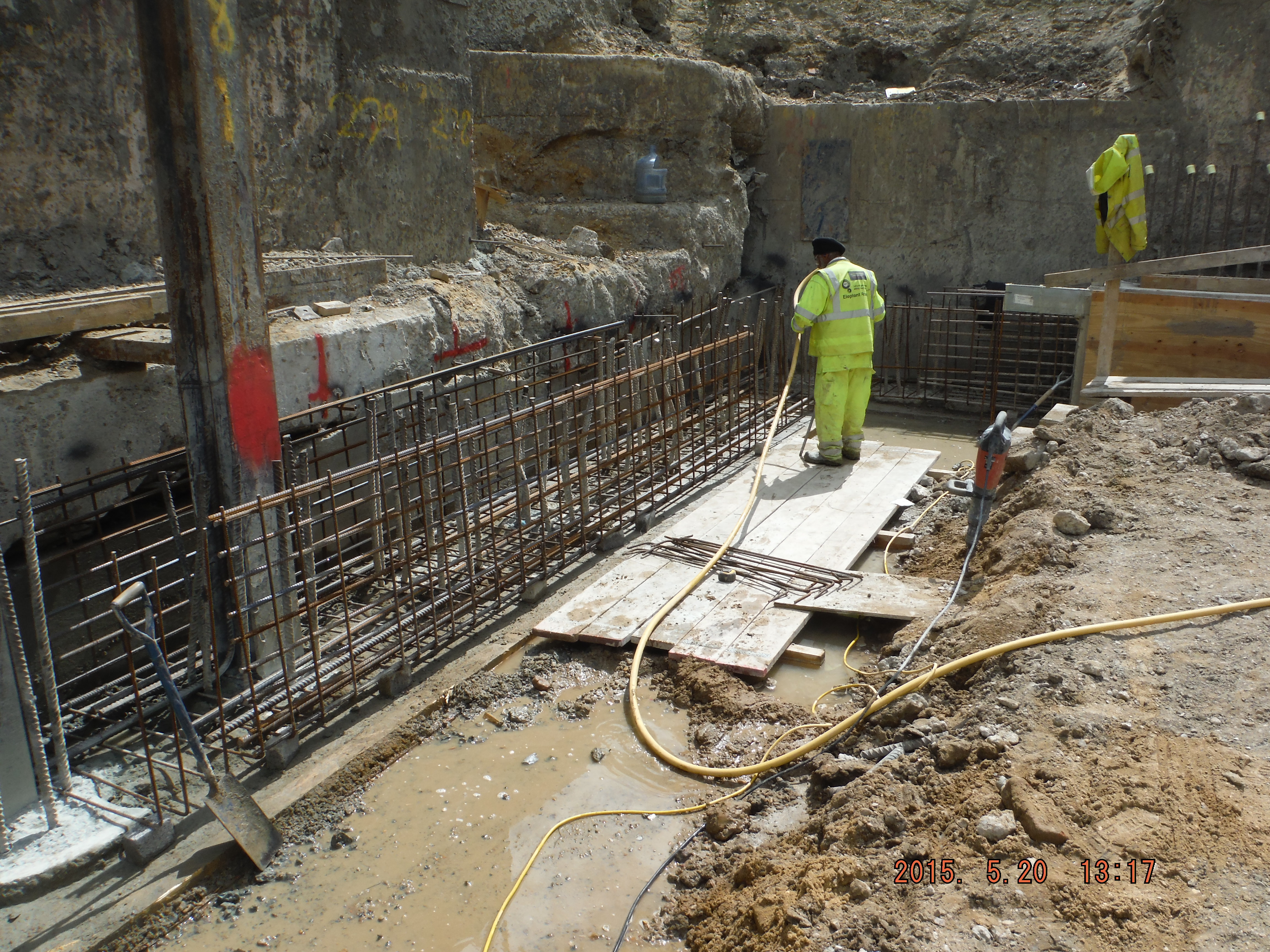
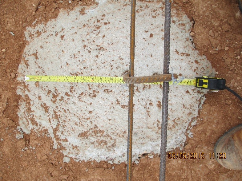
Away from the structural steel side of life a recent check on one of the columns revealed that the lap length was insufficient. Initially this was spotted by comparison to the contract drawings, which have a little table showing the required lengths based on steel type (60,000psi or 75,000psi) and diameter. This makes QC fairly easy. The specified length was 63” however only 54” was measured. The root cause of the issue was a sequencing error on the part of the contractor.
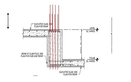
The column in question was a central column which had tie in to two elevated two way slabs at differing levels and the RC beam which forms a part of the monolithic frame of the building. This means lots of steel. The general idea can be seen in the diagram below – which is a general detail with the column rebar drawn in red for clarity. DEFINITELY NTS!
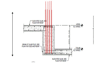
As you can see the lap measurement is intended to be from the base of the lower slab. Because of the ATFP requirements and the amount of steel required in the beams my suggested sequence would be to place the steel cage for the column and construct the beam through it. In this case however the steel for the beam was placed, and then poured with starter bars left protruding for the column cage to tie in with. This reduced length is obviously insufficient and outwith the specification.
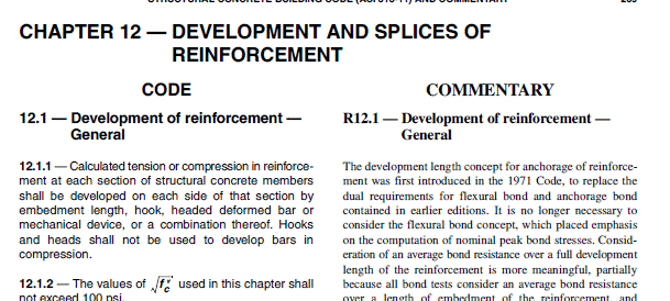
The error was immediately highlighted to the Principal and sub- contractor who were informed that they couldn’t close up the formwork and must put a hold on the following day’s pour. This obviously meant knock on delays to follow on slab pours. The only way forwards that I could see was to strip out the pour and start again, at huge cost in time and money or to lengthen the bars by welding, couplers or some other suitable method. I spoke with one of the other Project Engineer on site who checked the measurement and agreed that the error was too far out and we discussed a way forwards to try to minimize the delay. We looked at the lap length specified and he suggested looking to the Codes for a way out – specifically ACI318-11 which is the US version of the BS EN1992:1-1:2004. I broke out into somewhat of a cold sweat at the suggestion and was just about to propose ironing certain parts of my anatomy as an alternative but when he started to take me through the codes and to the relevant section on ‘splices’ I noticed that the code seemed somewhat user friendly – it even has a commentary section.
Excerpt from ACI 318
There is still the whole Eurocode-esque requirement to flick back and forth between referenced clauses, however in the e-version of the document these references are hyperlinked, so switching back and forth between clauses is somewhat less of a naus than the frantic wheel scrolling endured on the design exercises. Anyway – the calculation for the splice length is quite simple, just 1.3 x the calculated development length because this sort of splice is a Class ‘B’. In true Code style though, the development length calculation was almost an impenetrable mash of greek symbols.
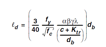
The commentary provided useful direction and actually most of the factors are taken as 1. So it can be seen that the development length is actually a product of Fy, Fc and bar diameter. In this case though I knew what the actual length was; I knew what strength steel we had and the bar diameter and so I adjusted the strength of the concrete until the calculated length matched the measured. This solution was acceptable, just about, based on restrictions in the design code about the acceptable strengths of concrete that could be used. It was calculated that a 10,000 psi instead of the 60,000 specified concrete would suffice. The proposal was obviously sent to the designer for their approval, which came back fairly promptly to proceed with the higher strength concrete. In the end the pour was only delayed by around two days, and now there are some super strength columns in the structure so everyone was fairly happy.
In other news we have a birds nest in our garden which has become the focus of some evening entertainment. So far the attrition rate of the chicks is around 50%. We are not sure if the two that we found lying dead on our patio were pushed by the other two, or if they just fell but at present king of the ring is a fairly brutal affair. Also, me and Danielle went to the tallest waterfall in Maryland.

Grand Designs Part 1
Although it has been a relatively sedate pace at BP it has certainly not been slow at home. Having moved into the new house 3 weeks ago I have already stripped 3 rooms back to plaster and floor boards ready for windows, plastering, electrics and plumbing.
Being a 1930s semi built with solid walls and suspended flooring, it doesn’t lend its self to being thermally efficient, so with my new found knowledge (thanks Mark) I aim to change that.

Approximate heat losses through building fabric
A quick lesson
For those not in the know, the U value, or thermal transmittance, represents the amount of heat lost (in watts) through a square metre of the considered fabric per degree of temperature difference between the inside and outside temperatures. So if the temperature difference is 20OC, U value is 1.4 and the surface area covers 2m2 then heat loss would be U x A x (Ti-To) = 1.4 x 2 x 20 = 56 watts.
When there is a combination of materials through which heat is lost, i.e. insulation, air gap and brick, then the overall U value can be determined by calculating the reciprocal of the sum of the thermal resistance, R values. In the case of 25mm insulation, 10mm air gap and 225mm brick the relative R values are 1.19, 0.15 and 0.3 m2K/W respectively and additional thermal resistance of 0.04 and 0.13m2K/W are also considered for the outside and inside surface resistances. Therefore giving a total U value of 1/(1.19+0.15+0.3+0.04+0.13) = 0.55W/m2K. Simples!
Windows
Current windows are approx. 15 years old and in some places, much older. Solution: Upgrade with new uPVC double glazing filled with argon with a U Value of 1.4 w/m2K. The value of 1.4 is below building regs part L1a value of 2.0 for new dwellings.
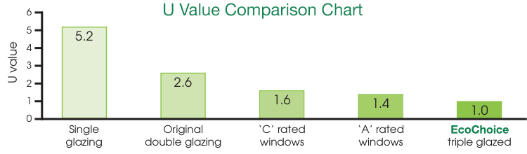
General window U values
Walls
Current walls are 225mm solid brick with a U value typically of between 2 and 3 W/m2K. Ouch. Solution: apply 25mm rigid polyisocyanurate (PIR) insulation to the inside of external walls to reduce overall U value to 0.55. This does not reach the part L1a value of 0.3W/m2K but in order to reach that value then an insulation thickness of approx. 60mm would be required and a compromise had to be made.
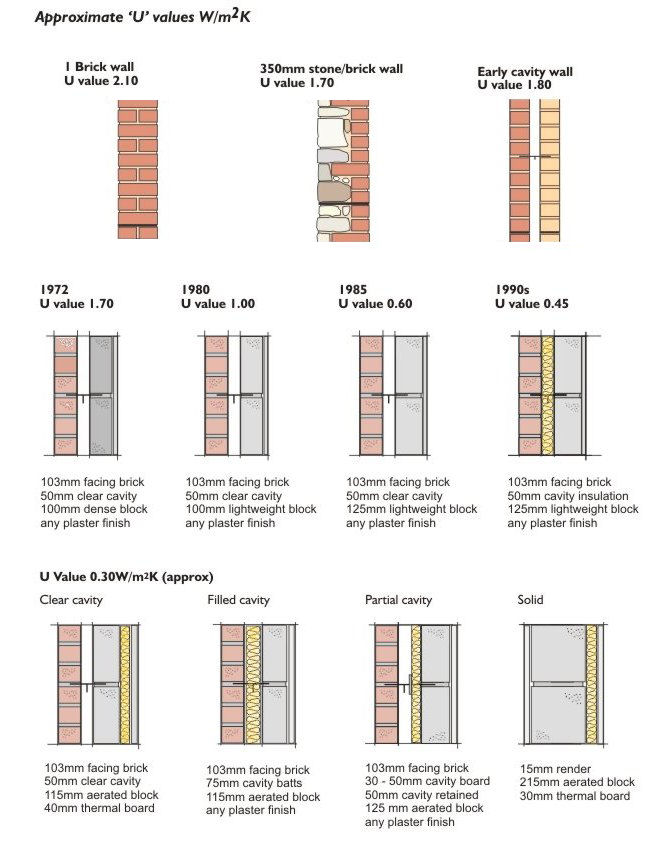
General wall U Values
Ground floor
Currently the flooring consists of 18mm floor boards and carpet giving a U value of approx. 2W/m2K. Solution: addition of 50mm PIR insulation will reduce the U value to 0.35W/m2K which is higher than 0.25 required in new buildings but a compromise had to be made with the increased cost and depth of floor joists.
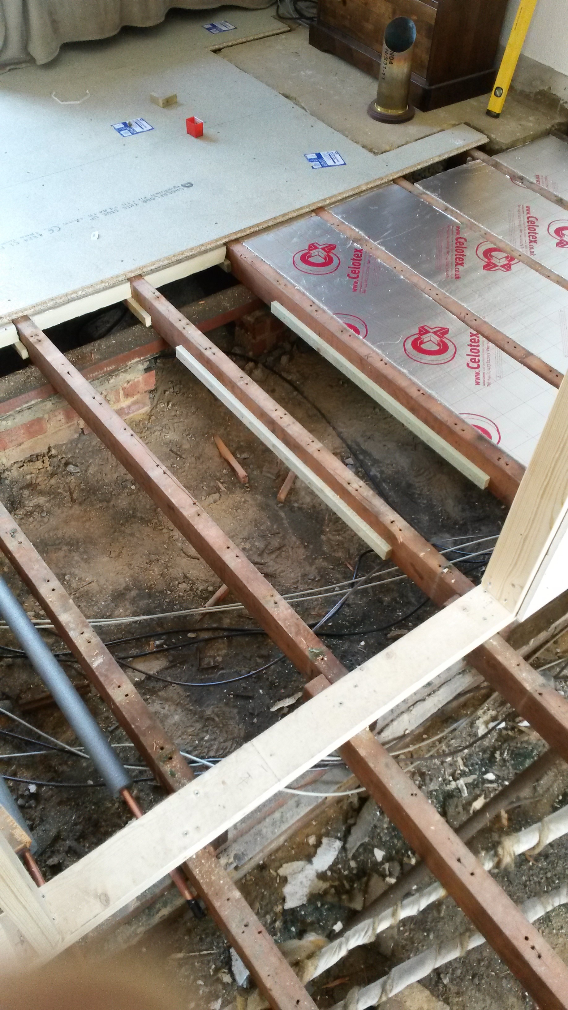
Progress as at 6 Jun 15
(current state above. You will notice a whole host of cat6, coax and HDMI cables running under the floor)
So what?
Reducing the U value of windows from 2.8 to 1.4, reducing the walls from 2 to 0.6 and reducing the floor u value from 2 to 0.37 will ultimately reduce the heat loss by approx. 75% and therefore reduce gas bills. I forecast the total cost of these upgrades across the house will be approx. 16k with windows taking up 12k of that. Average current gas bill, say £100/month, therefore savings £900 a year, therefore a payback period of nearly 18 years!! But at least I have that warm (excuse the pun) fuzzy feeling of doing my bit for the environment.
Next step
Size emitters (radiators) to each room given the surface areas, U values above and internal and external temperatures of 21 and -1OC respectively and size boiler given the emitter sizes and hot water demand calculated.
Final thought.
During a conversation with a sales man from Everest Windows (other window suppliers are available), he said that it is not worth getting triple glazing as the additional money you would save on the gas bill due to the higher U value would be countered by the need for additional lighting due to a reduced level of light because of the additional pane of glass.
Service diversion.
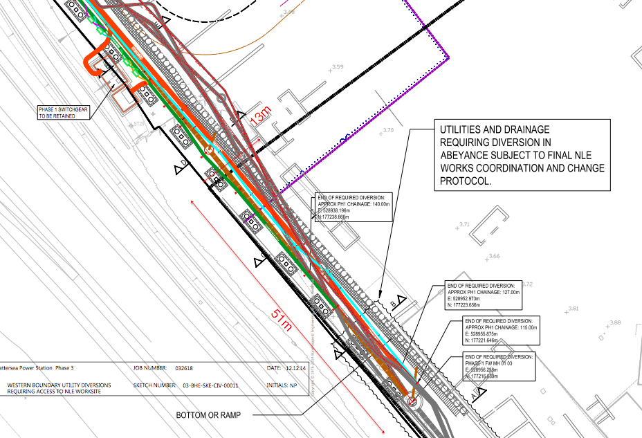
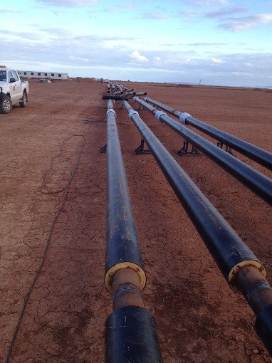
This week’s blog will revolve around the services along the western boundary of phase one. The services that are currently in position were put in by Carillion last year as per the agreed design. These services include HV cabling that provides power to the temporary transformers on phase one as well as phase 2. That’s 3.75 MVa of power for phase one alone. The key point to takeaway is the HV cabling is live and being used. The other key service is the foul water, which needs to be in situ to allow commissioning to take place.
Unfortunately (for the client) the as built services now appear to run smack bang through where phase 3’s basement (crisscrossing in and out of the sheet pile wall) will be. Phase 3 cannot be re-designed so the services are going to have to move in order for phase 3 to go ahead. This ideally needs to be done by October this year as that’s the start date for phase 3 (main contractor not announced yet) and it needs to be done whilst keeping the power on to phase 2 and 3. To complicate matters phase 3 is being built on top of the Northern Line extension (NLE), the ground works for which have already started.
Carillion were briefed by the client’s consultant Burro Happold (BH_ two weeks ago as to the situation. Three COAs were presented and the preferred (selected by the client and BH) COA identified for CCL to pursue. We will be back briefing this week. The brief we received with respect to the three COAs considered was:
COA 1 single stage plan
The first option for diverting the Western boundary utilities and drainage is a single stage diversion. This entails providing temporary power generation to the ongoing Phase 1 and 2 construction works. This will enable all of the existing utilities requiring diversion to be removed and constructed along their permanent alignment in one single stage of works. Once complete, the diverted utilities and drainage will be energised and temporary generation/alternative supply will cease. This will then result in the phase 3 sheet pile wall being installed as close as 1m away from buried live HV.
COA 2 two stage plan
To avoid the need for alternative supply and generation to the ongoing Phase 1 and 2 construction works and subsequently piling in close proximity to a live service, a two stage diversion plan was considered. Within the two stage plan, power supply is maintained via a temporary HV diversion within the Phase 3 site, avoiding the basement secant piling wall line. Once the temporary duct alignments are installed, a swift switch over is undertaken at convenient connections to the existing HV network, facilitating the required diversion works to all of the utility networks along the western boundary. Upon completion of the diversion works, piling along the western boundary corridor can commence within the Phase 3 basement. Upon completion of piling, power and water supply can be swiftly switched back to the new diverted utility alignments, with the temporary arrangements subsequently de-commissioned.
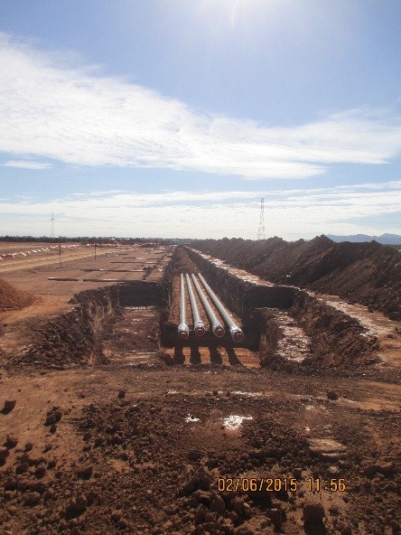
COA 3 Tunneled Drainage and Phased Utility Diversion plan.
To avoid the need for alternative supply and generation to the ongoing Phase 1 and 2 construction works, a tunnelling option has been explored for the installation of the diverted foul drainage network to remove the majority of the required diversion via open trench installation whilst maintaining live services. Within this option, the launch shaft at an existing location will be utilised to tunnel the diverted foul drainage route north to a new reception shaft. From this reception shaft, the remaining 30m of required drainage diversion can be installed via open trench installation.
Upon completion of the foul drainage diversion, works can commence on the diverted HV supply alignment. The new HV alignment has been designed to avoid the existing live HV supply where possible, however some crossings are still required (notably at the existing entry and exit to the existing switchgear). In addition, the diverted HV alignment is required to cross the existing Phase 1 water supply. The plan would then be to conduct one shutdown and switch over in a very ambitious 48 hour period.
Chosen COA:
The tunneled drainage and phased utility diversion plan has been selected as the preferred COA for the Western boundary utility diversion works. The key risks associated with each COA are summarised in fig 1. BPSDC and BH highlighted the main drivers behind the selection of the preferred COA as being the costs and procurement risks of temporary HV supply as well as the potential to delay the final commissioning of the Phase 1 building (which requires completion of all associated utility networks) at the end of 2015. As the Phase 3 piling works are unlikely to commence until October 2015, it was deemed inappropriate to consider the two stage plan.

Fig 1. Risk matrix
Thoughts / reflection
Every time I re-read the three options that were presented by BH and the client and look at figure 1 I can’t help but think that the client is placing programme and cost implications well above the safety of the work force who will have to carry out this work. If something goes wrong I’m struggling to see how they will be able to prove that they did everything practicable to remove the risks that working close to HV presents; despite the use of tunneling the chosen COA will still involve new services crossing existing HV with hand digging installation method, which the client wants to keep live, 4 times. This is completely avoidable if either of the other two COAs were chosen. This is going to be highlighted at the back brief to the client, but I very much doubt we will get them to change their mind. The only thing that may throw a spanner in the works is that Carillion policy is to not work with live HV. So the choice of COA 3 may yet still result in temporary generation being required.
Questions for the PET community.
I’d be keen to know the civil’s view on piling so close to live HV. E.g. What happens if piles start to fail? The current plan is to place visual guides at the locations the piles will be driven as we place the new HV cable. This is to give the piling contractor an additional degree of certainty that they are not about to hit a HV cable.
I’d also be keen to know if the M&E community thinks I should be getting involved in this. Obviously the services themselves are M&E base, but a lot of the work associated with getting them in is civils. I think there could be an opportunity to get plenty of B1-3 competency experience. Thoughts?
A drawing attempting to highlight how tight everything is going to be. Orange is new HV, brown is is new drainage. Existing services are greyed out.
Not as good as Damo’s…
I started this as a reply to Damo’s blog but it became a bit epic so I thought I’d make it a stand-alone blog. So it you haven’t read his; read that first, or just instead, it’s better than mine anyway!
The client has contracted BLP as its insurers for the project. They visit at certain times to inspect the things most likely to cause a claim. At this early point in the build it’s waterproofing. McAlpine are still picking up the pieces from a job finished last year where the basement is now leaking. They have spent over £1 million injecting grout into the walls and water is still getting in. Later on the insurers will care about the façade, and the roofing, anything that could let water in. But right now it’s all about the waterproofing under the concrete.
It’s not that BLP don’t care if the building falls down, it’s just that thanks to all the other checks that happen, and likely hood of such an event, they’re focussed on the stuff that might cost them money in the long run. They just assume the actual structure will be alright.
They have paid particular attention to manholes. And quite rightly, as the first 3 we built we massively messed up!
The first isn’t waterproofed at all. The second is, but a movement joint was incorrectly installed and now the membrane is torn, and the third one used waterproof concrete that it turns out is less than waterproof. All of these will require remedial waterproofing works which we are waiting for the waterproofing designer to come up with before the architect approves it before we can instruct the install.
To add further complication these three manholes were installed by our previous drainage sub-contractor who walked off the job some time ago after they hadn’t been paid. When our new drainage sub-contractor surveyed the manholes they discovered that at best the invert of the inlet was level with that of the outlet, and in one particular case the inlet invert was 40mm higher that the outlet, see picture below.

The worst manhole ever!
The curved 100mm dia (4” for Brad and Henry) pipe is the inlet. The straight 150mm dia (6”) straight pipe is the outlet. The reason the 4” is curved is because it enters the manhole at such an awkward angle that the benching would be a nightmare so a curved bit was added. By removing the curve (requiring local breaking out around the joint half embedded in the wall) we managed to achieve a 15mm drop (whoop whoop) and we’re hoping that with some artistic benching we can make it work. Luckily that inlet comes from a floor gully, so at least we don’t have to worry about trying to get a poo round the corner!
I’ll keep you posted…
In other news I have managed to talk two blokes from my site into the Care Construction Challenge, a 26.2 mile cycle, run and kayak race in the peak district. We all have to do all the legs and I have promised that if we raise our target amount that we’ll complete it in dresses. So please sponsor us at https://www.justgiving.com/LillieSavages/.
Thank you!
Site Two Fifty One – Commercial Aspects
Site Two Fifty One – Commercial Aspects
I will turn attentions to some commercial aspects this week.
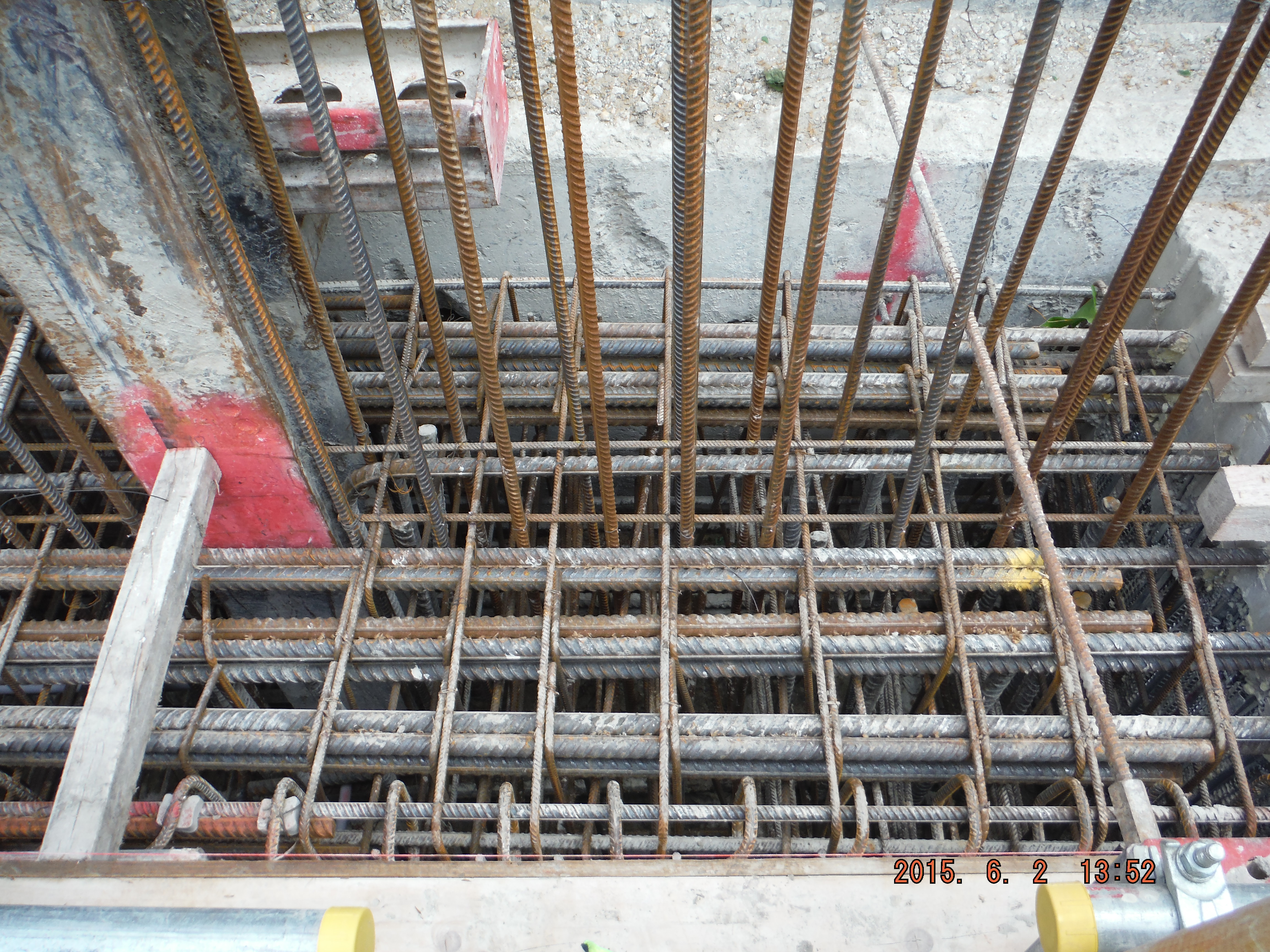
Firstly, warranty and building insurance. There were two inspections of the capping beam recently. One from Assent Building Control and one from AECOM. The purpose of each was slightly different.
Assent Building Control inspections are to confirm that the building is being built in compliance with Building Regulations, i.e. planning requirements. The inspection was of reinforcement for the capping beam. The inspection included a general look over the area and to make sure the cover to steel was correct. There did not seem to be much reference to the Building Regulations – Approved Document A (Structure), Parts A 1&2: Loading and Ground Movement, or Part 3: Disproportionate Collapse. Now clearly the project is at an early phase, and the inspection was of a ground beam, but I would have expected slightly more inquisitive questioning. It felt like it was as much a waste of the inspector’s time as it was mine!
The client has also engaged Allianz Insurance to provide a 10 warranty on the building. Allianz have then engaged AECOM to provide external, independent quality assurance that the structure is being built in accordance with the design. The inspector had extracted relevant drawings from ASite (file sharing website) and was keen to see the section of capping beam that the 40 storey building is going to sit on. The 9 x H32 top and bottom bars, acting in bending, were checked and he was happy. The mass of other steel (for temporary props) was not his concern because he will provide the insurance for 10 years after completion of the structure, not if it falls down in construction.
Capping beam reinforcement cage construction
So what?
It is good that AECOM chose to visit an important part of the structure and that the key part of the steel was checked (and that the inspector had printed drawings and knew what he was coming to look at). I think this shows more of an appreciation of risks involved than just a generic check as per the Building Control one.
Second part – Contract or not to be…
The project I am working on started with an enabling works 26-week contract which covered a secant pile wall, tower and office bearing piles and the pile capping beam. We are now in about week 30 and there is still no full contract. Laing O’Rourke had previously quoted a price in January 2014 which was 10 million lower than the contract price submitted a few weeks ago.
This has prompted an intensive period of value engineering to see where savings can be found. The in-situ basement box and precast frame were re-costed reaching a similar total but the mechanical and electrical and fit costs out have increased.
So what?
The building price has increased by about 10%. The value engineering meetings have found savings but also additional costs.
The client is also pushing hard for sequential/early occupation. Great to get people into their flats early, but at the same time this creates havoc with commissioning – I understand it is difficult to only commission half of a fire alarm system and equally expensive to commission a lift shaft more than once. Therefore the benefit of improved cash flow gained through early occupation is lost in additional commissioning costs.
So so what?
Not having a full contract and running on a rolling monthly extension to the enabling works contract makes organising the project difficult:
Precast – Laing O’Rourke are the pioneers of precast: columns, walls, beams and slabs (Design for Manufacture and Assembly). Great idea, but if the lead time is 22 weeks for production, a rolling contract is not the way to get things done.
Designs – Without a contract, the detailed design is being completed ‘at risk’ and each component part (sub-contractor) of the project is a little wary of committing time without the assurance of a contract as to whether the building is going to go ahead.
Today we had an unannounced visit from Des O’Rourke – co-owner of Laing O’Rourke. Not a common occurrence, so with a visit yesterday of another senior director, I suspect it is coming to crunch point on whether the project gets the green light beyond the enabling works! It is an interesting time in construction in London – there is no shortage of work for contractors and so I think if a client wants something, they are going to have to pay for it. Gone are the days of simply agreeing on projects to retain cash flow (at least at the moment).
I’ve been a bit light on photos, so here are a couple of other ones:
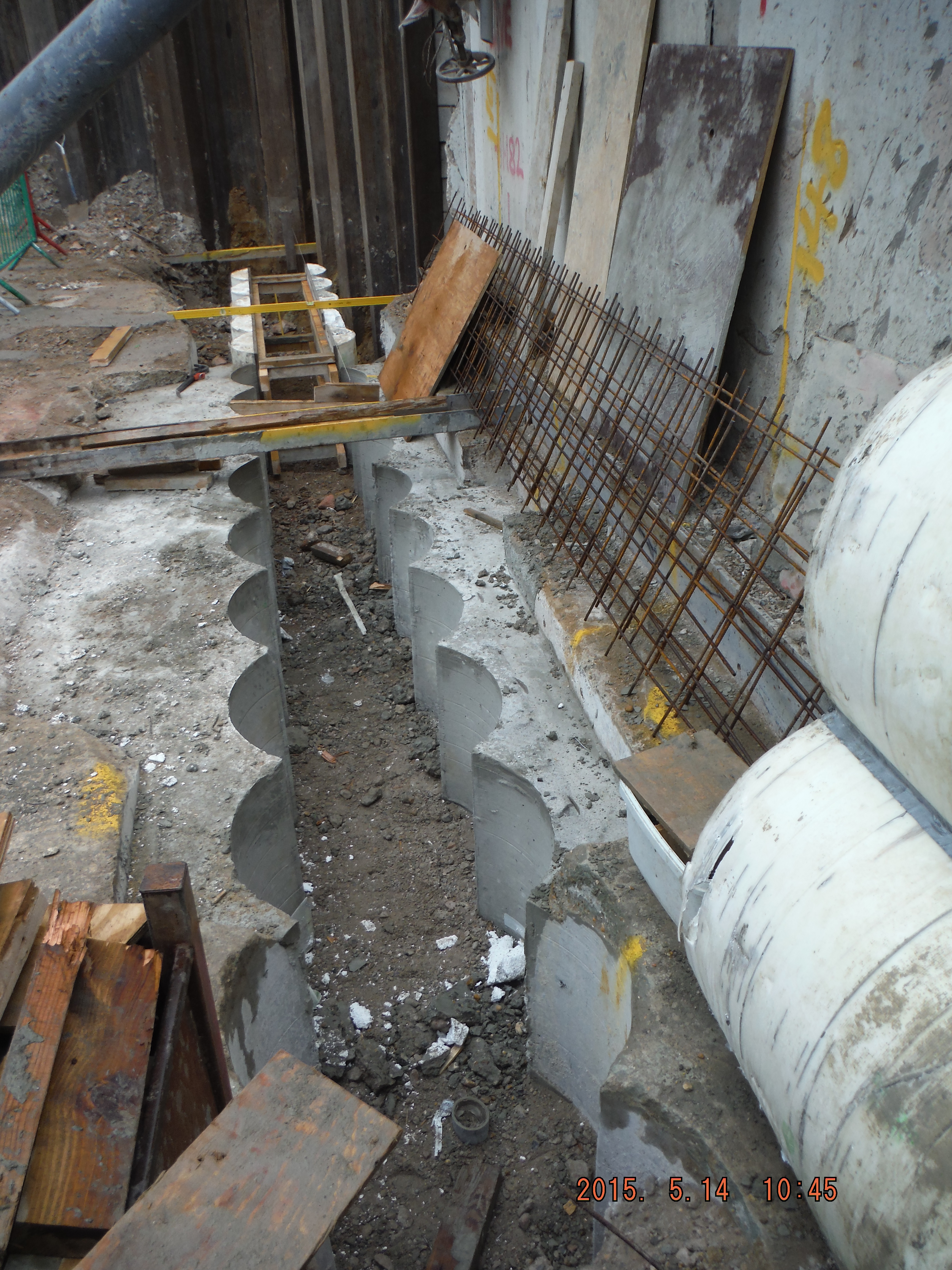
Guide wall construction using polystyrene formers:

Post pour “half-moon” interlocking secant wall
UKMCC Bahrain update
Hi all,
I’ve bunged a few more photos from Bahrain onto my blog. Namely posts about staircases and floors and one about E and M experiences.
I’ve got 2 more posts to put on: Civil Works and Finishing Details and then that’s me! Project finished.
As this is voluntary for me I have not put too much writing on there, just photos. Please let me know if you need any information. I’ve learnt heaps, particularly about E and M as you can see.
As I always wished for other people to have access to my blog I am not using your area, but instead am on
https://roselliott.wordpress.com/
Enjoy!
RE
General observations
It has been a while since I last blogged and has primarily been down to the relatively sedate pace of life up in Aberdeen. In an attempt to prove I haven’t gone native, I thought I would pen a few points and observations I have made over the last month or so.
Continual Uncertainty
The oil & gas industry is still in a bad place and not likely to recover for a while. Woodgroup (whom provide a lot of engineering services to the BP Projects & Mods team) announced a couple of weeks ago that further job losses will be required and uncertainty exists as to what that exactly means. Last week they also announced that their engineering teams based in Aberdeen will be moving to Glasgow in order to reduce costs and increase productivity; so what? For me, it will almost certainly mean frequent commutes to Glasgow in order to better coordinate projects.
BP itself is continuing its drive to improve efficiency throughout the entire organisation and a ‘town hall’ with Trevor Garlick, the Regional President put it in perspective. When looking at North Sea producers, BP currently sits in the bottom third in terms of cost per barrel to extract at around $37 per barrel, even if that was reduced to say mid-twenties, BP would only rank in the middle third. This is primarily due to the huge overheads BP has because of the size of the organisation; BP cannot compete with the smaller independent oil producers in the North Sea. In order to save money, budgets have been cut and are expected to be reduced further next year including the P&M budget.
Procedures
After initially being impressed with the documented processes and procedures that exist, it now seems that BP staff understands them in the same way we understand AFM, SOHB et al. We know they are there and roughly what they are about but they are not always fully understood, at times don’t support each other and may not be up to date.
When you are both behind schedule and will finish early
There is currently a project being executed offshore to deliver an additional lifeboat so that there can be an increased number of pax working on the platform at any one time. The project started in early Mar and was scheduled to complete in 4 weeks. As you can see from the S-curve below the project is about 7% behind schedule but we have been told that it should be complete in a week; so in a 13 week project the last 23% will be completed in the last week. This is really down to poor forecasting at the beginning of the project by vendors who are completing the installation and final commissioning of the life boat. Arguably it’s not that big a deal as long as it is completed within schedule, but it does raise some eyebrows further up the chain and brings some unwanted questions. So it is not just the army that tries to mould figures to appease higher HQs!!

Timings, Timings, Timings
I know that a few of you have mentioned this in blogs previously, but think it is appropriate to quote Barbossa from Pirates of the Caribbean: Curse of the black pearl when describing contractor deadlines;
“the code [deadlines] is more what you’d call guidelines than actual rules”
In other news
Pregnancy: Still, but I’m the one putting on weight and having food cravings (olives at the moment).
House: moved in, more to follow.
CPD
Brendan and Myself attended a CMI coordinated breakfast, titled ‘Leading in Difficult Times’ which included 3 guest speakers. Lt Col Paul Binnie, Commanding Officer of AUOTC discussed the role of the leader in terms of subordinate development, mission command, clear communication and inspiring your team. Ella Minty, a strategy and change consultant, discussed the concepts of knowing your limits, knowing your boundaries between work and social, seeking results, ambition and real value and fostering challenge, trust and learning, and finished with the line “if you are the smartest person in the room, you are in the wrong room”. The final speaker was Bob Keiller, the CEO of Wood Group who played 7 songs and discussed each one in tern;
Black Sabbath – Paranoid
The Temptations – Get Ready
Animals – Don’t let me be understood
The Matches – Needs and Wants
Paper Lace – Don’t be a hero
Elvis – A little less conversation
Crowded house – don’t think it’s over
I’ll let you decide what he meant by each one.
Oz PCH – Knock-on Effect Issues
Diagnostic Imaging Unit (DIU)
I’m going to discuss an issue (small relative to the majority seen) but one that highlights a good example of the knock-on effects of last-min (late) design change.
The DIU houses the imaging equipment found in most modern hospitals the biggest pieces being the Magnetic Resonance Imaging (MRI) scanner. Here there is one to be installed with a further two areas completely fitted out (inc all control equipment etc) to be installed for future use. One of these future pieces is to be a Position Emission Tomography (PET) MRI scanner. PET is used when searching for cancerous tumours predominantly in the head, brain, neck and prostate and gives clinicians vital info like metabolism or physiology of the tumour. So, when coupled with MRI (used for soft tissue imaging like a CT scan would but with the added benefit of not exposing the patient to ionising radiation – important in paediatric oncology) it allows a key advantage over pure PET alone as PET is not capable of accurately assessing the local extent of the primary tissue in certain locations of the body like the head and neck, whereas MRI can (HealthPACT, 2012).
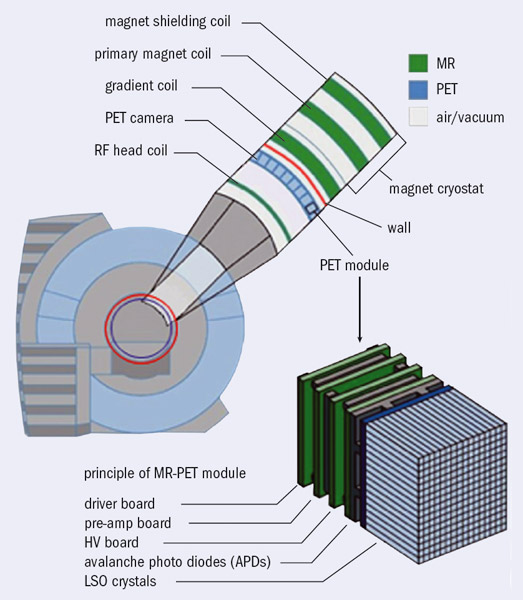
Scanner Construction.

Siemens PET – MRI Scanner.
Architectural Design Issue
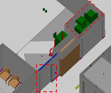
The DIU was originally designed (by the Architects BCJH) to be located on the ground floor but…and I can only presume due to lack of stakeholder engagement even though BCJH are an amalgamation of specialist hospital design architects so should know better, that particular area was right above the upper basesment car park as the red dotted rectangle (PET MRI room) depicts below when comparing both ground and upper basement floors. The blue dotted rectangle being the new location sufficient distance from the car parking spaces below.
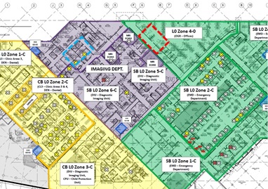
Ground Floor – DIU dept shaded purple.
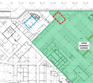
Upper Basement – Carpark in shaded green.
The issue is that each MRI room emits a large electric field as a result of the MRI technology using super strength magnets. Due to the design of the magnets, being symmetrical, the electric charge produced, found using Gauss’ Law as the below pic shows, creates some very serious problems. In simplistic terms the electric field is so great that there are limits to the proximity of moving (dynamic) metal objects in order for the scanner to work correctly and not have the metal objects causing discrepancies in the scan results. So you can imagine the surprise when the clinical technicians (stakeholders) found out about a carpark full of potentially huge dynamic metal objects right beneath their scanners. The Gauss Field seen in the pic below isn’t of the PET MRI room but of another MRI room for illustration purposes – the 0.5 mT (red field line) is the one that can affect humans and metal objects (like people walking past with a pacemaker fitted) and so is the one that must be contained in the Faraday cage. As a rough comparison your standard vacuum cleaner (generally emitting the highest magnetic field strength of any appliance found in the household) gives out 0.13 – 2 µT at a distance of 1m away vs a MRI scanner giving out 10 – 20 mT at 1m away. The MRI scanner being x 103 (1,000 times) higher but the exposure time of the MRI scanner is seconds versus minutes when operating a vacuum cleaner.
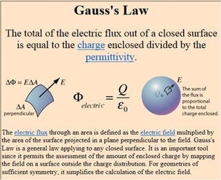
Gauss’ Law.
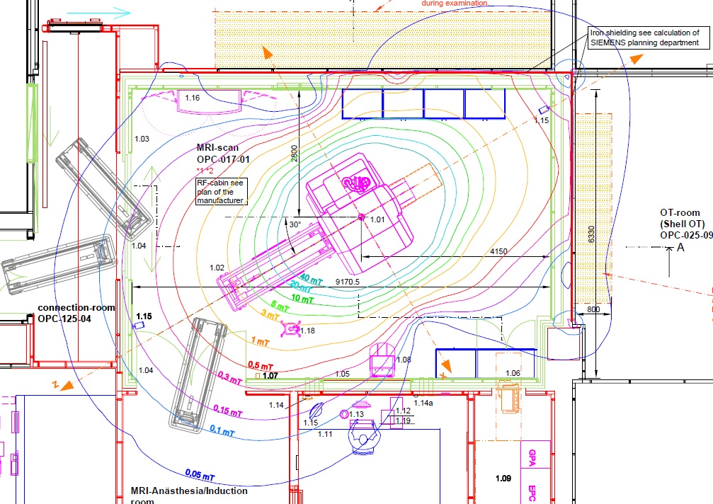
Gauss Field of MRI Scanner.
To reduce the effects of the Gauss field a faraday cage is constructed made of copper sheeting that is attached to the inside of the room via wooden battens and acts as a ‘force field’ surrounding the MRI scanner (charged particle) by basically conducting the charge thus stopping it spreading any further. However, the charge creates high levels of electromagnetic radiation which are potentially harmful and so a skin of silicon steel sheeting is attached to the outer side of the wooden battens in order to stop it. This construction is the same all the way around the scanner with the only slight difference being how it is placed into the floor. The pic below shows the set-down (72mm cut-out) in the concrete slab where the 6mm silicon steel sheets are placed followed by 19mm particleboard acting as a divider before the copper sheeting is added. Finally a 16mm particleboard, a 12mm particleboard and a 3mm vinyl sheet flooring are added coming up flush to avoid any raised edges in the finished floor (required for trolley wheels and eliminating as a trip hazard).
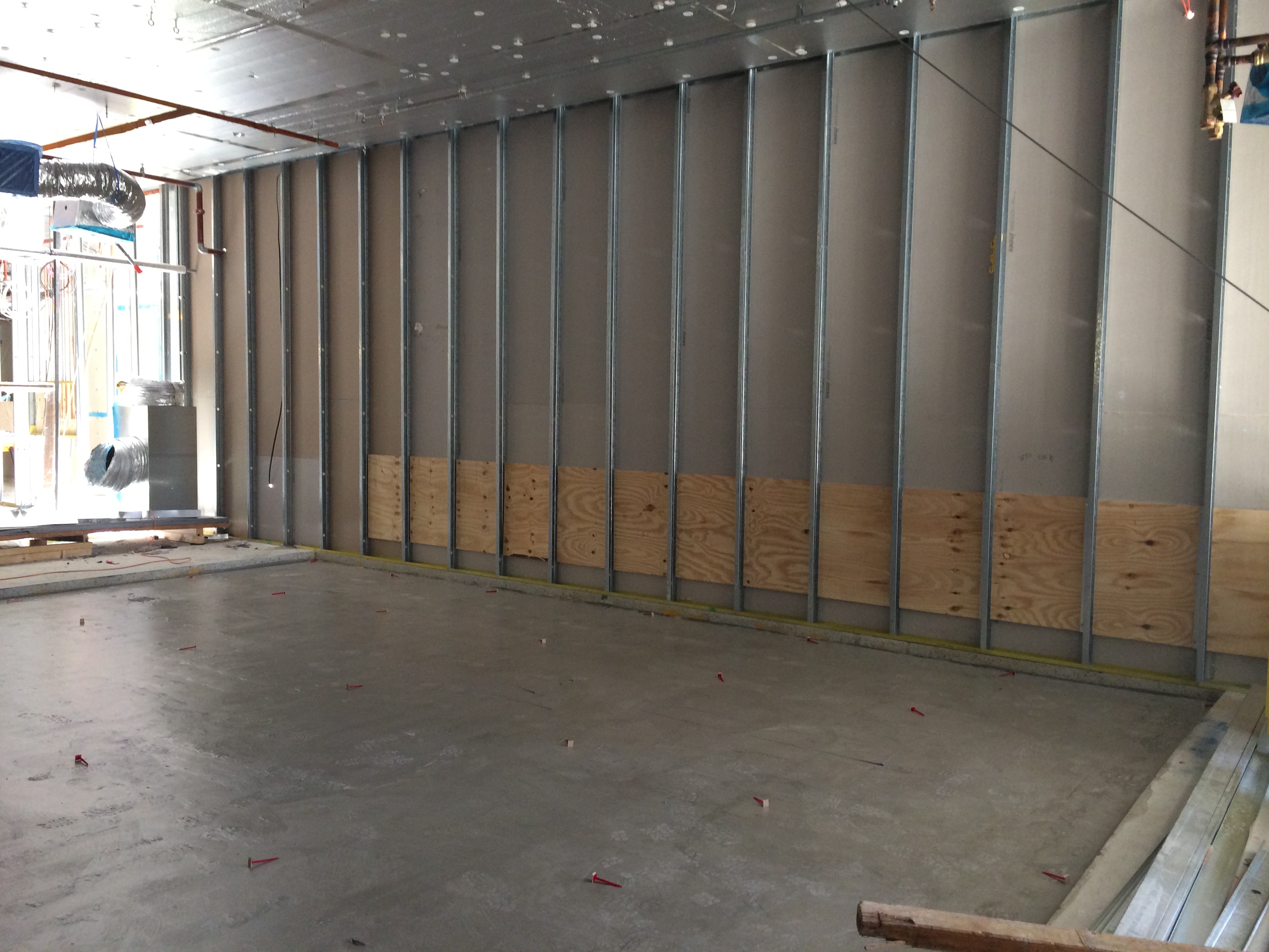
PET- MRI Room showing Set-down in the concrete slab.
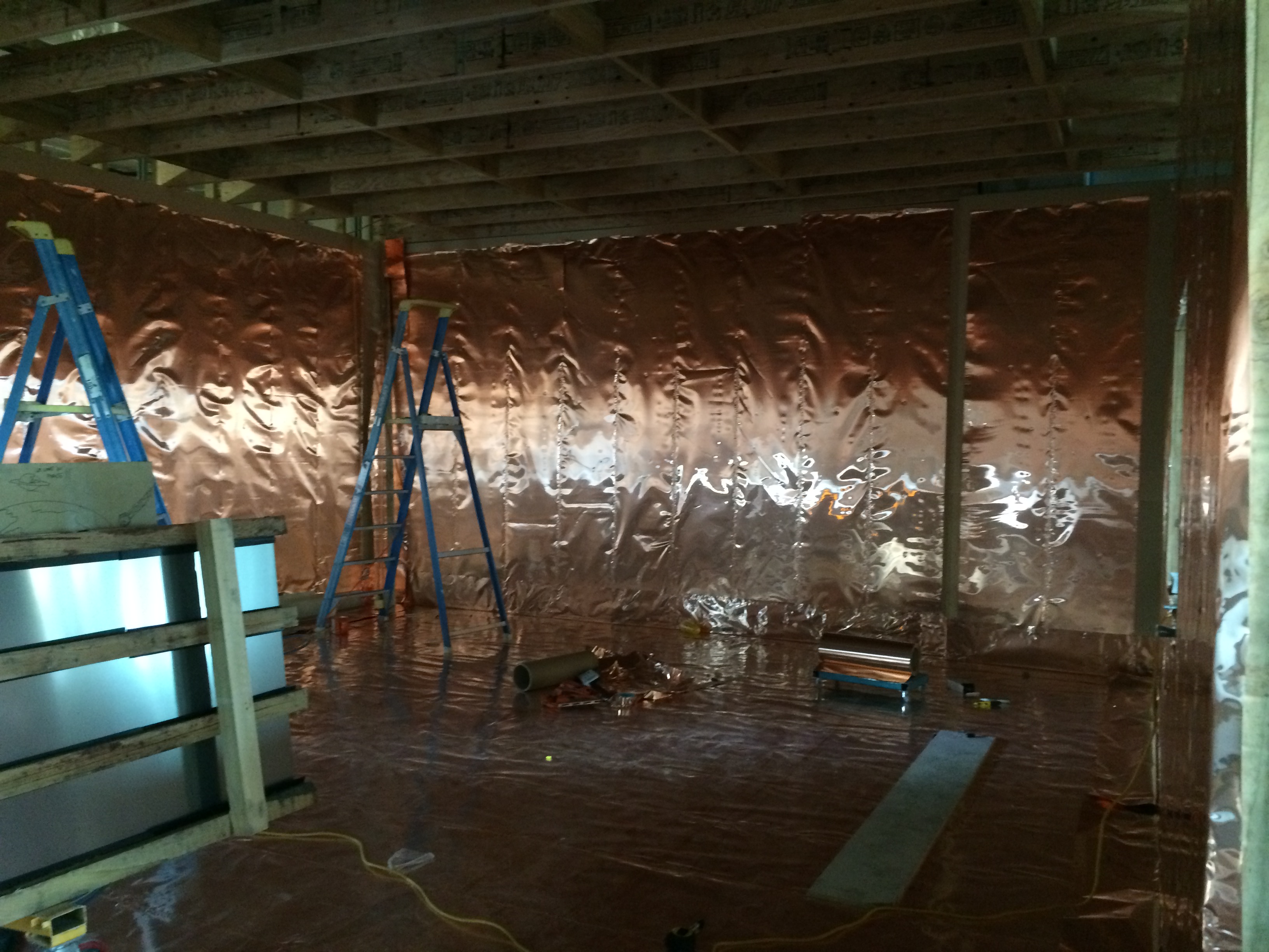
MRI Room showing the Copper Faraday Cage.
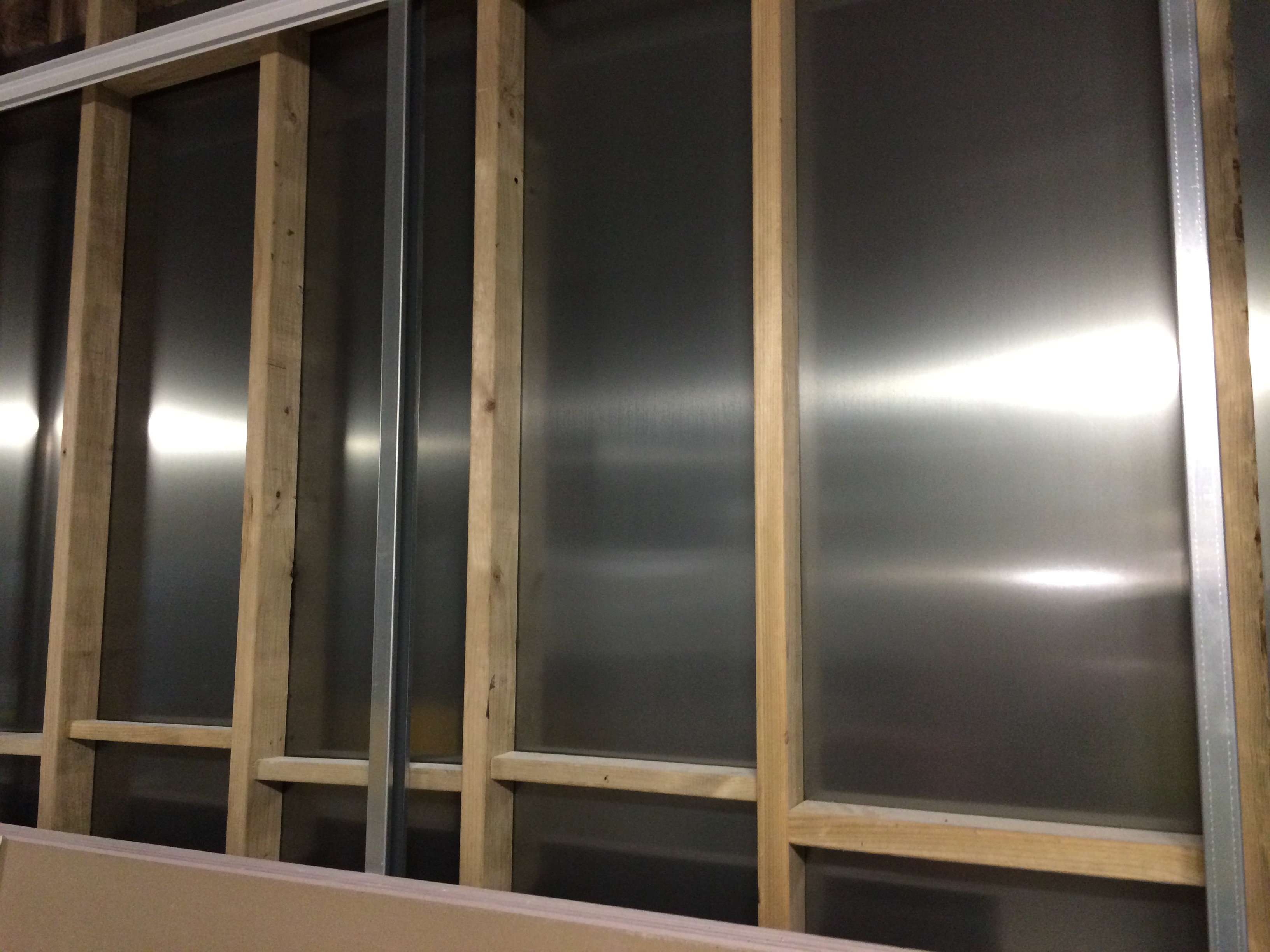
MRI Room showing the Silicon Steel Sheeting from the outside.
So although the faraday cage should stop the electric field getting out there are still obviously key technical design reasons why you don’t want it sat on top of tens of tonnes of metal cars moving around causing dynamic interference. This could be a good technical TMR topic, something like ‘what technical considerations should be investigated in the design and construction of a MRI room in a hospital and what design provides the best protection’?
Solution
A very expensive complete department move. Due to the functional interoperability of the department you couldn’t just relocate the MRI rooms per se but the entire department. The DIU is still on the same floor but now moved away from any potential dynamic mass of metal. Contractually JHG have put in a claim to the architects as moving the whole department has/will cost $ hundreds of thousands.
Knock-on Effects
Apart from having to redesign the layout of that particular area of the floor, including the requirement to fill what was going to be a source of natural light through an architecturally pretty glass roof will concrete, other building services issues arose.
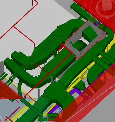
The BIM federated model below shows part of the PET MRI room. The orange rectangle is where a partition wall is yet to go up that divides the scanner room to the left and the electronics room (red dotted rectangle) to the right. In here the larger green box in the enclosed walls houses a Fan Coil Unit (FCU) for that floor area, the smaller green box is the dedicated cooling unit for that electronics room and the red piping/blob (barometric damper) is the pre-action fire suppression sprinkler system which had to change from a normal automatic wet sprinkler system so as to avoid potential water damage to the PET MRI scanner (approx. $2 million) meaning the barometric damper could not be put in the actual room due to the faraday cage.
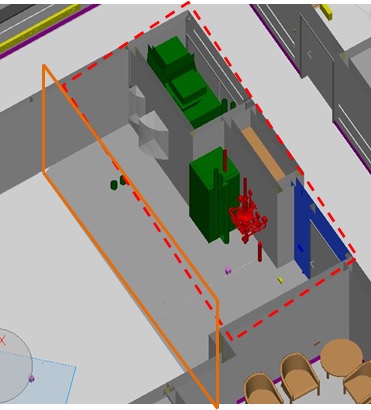
BIM Federated Model of PET – MRI Room and Electronics Room.
The on-site photo below (taken from the edge of the partition wall) shows the internal framework of the surrounding walls – you can make out the FCU compartment (dotted red line) and the ductwork, insulated supply (blue arrow) and extract (red arrow).
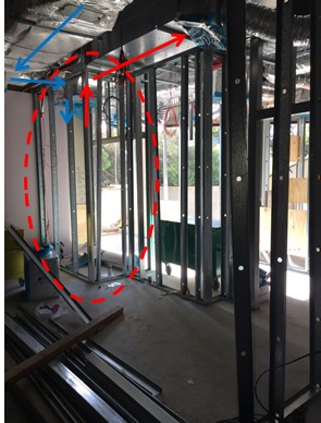
Electronics Room showing FCU location and ductwork.
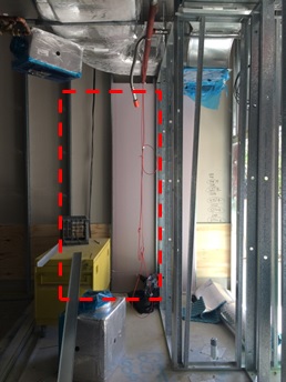
The issue is that Siemens need to install their electronic equipment in this room (including the electrical safety working zones required) and are fighting for space even using the partition wall (orange rectangle). What’s making the situation worse is that FCU has been installed 180 degrees round the wrong way making the inspection/maintenance access doors completely redundant and requiring extra door panels on the inside of the room as seen by the grey arcs depicting the swing radius of the two inspection/maint panels in the BIM model above. Below shows the original FCU access doors and the main room door which is now planned to be outward opening (into the corridor) and moved round the corner.
Electronics Room – Corridor View with current door location.
The proposed new door location, shown below (red dotted line not to scale) will just fit at 1m in width.
Proposed new door location.
The obvious solution would be to turn the FCU round by 180 degrees so the inspection/maint panels marry up with the access doors however as shown in the model below and first photo the supply and return ductwork is already installed and there is no space or desire to change as this would be costly. Siemens have now been tasked to detail exactly what wall space they require for their equipment in order to resolve the issue.
BIM Model of Ductwork in ceiling space.
The below annotated dwg is the proposed solution for Siemens and we are awaiting their final decision. Note the faraday cage (dashed green line around the perimeter of the scanner room) and in the electronics room the green boxes are the location of equipment with the orange boxes being the safe working zones so you can see how tight it is. Also, the shaded green boxes are the space gained by relocating the door round the corner so Siemens should be satisfied.
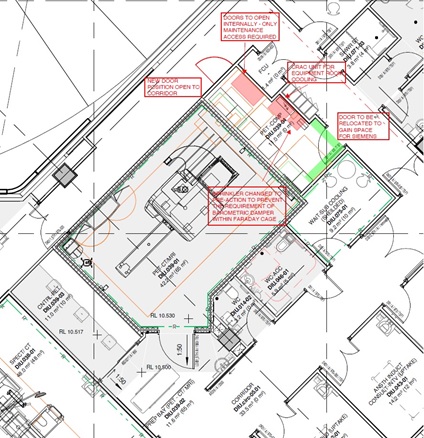
Shop Drawing of relocated electronics room access door and FCU maint doors.
HSE and Quality Control
This blog aims to explore some of the issues associated with working with subcontractor who have little experience working for a Tier 1 contractor. It will look at a number of examples that have come to light recently on site, relating to both quality control and health and safety.
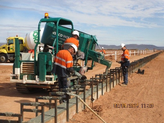
In my first blog (20 Apr 15) I mentioned the fact that one of the risks identified by John Holland (JH) was the use of subcontractors not accustomed to working with JH procedures, this has now begun to be an issue on site. The first case was highlighted in the previous blog and involved the rejection of too loads of concrete due to the lack of an adequate Inspection Test Plan (ITP). The impact of this was a two week delay on the program for the first greenhouse and it contributed to 25% wastage of concrete (the decision on who is to pay for this is still to be confirmed). The delay was caused by the failure within Van der Hoven (VDH) to agree what standard the structures were designed and constructed to and thus what tolerances had to be used. This led to numerous conflicting tolerances, some of which the construction force were unable to meet. In the end the ITP was developed by JH and given to them in order to progress works.
Pillar Foundation – Yes the hair pin is supposed to be in the centre
Wall Foundations
Further issues have now arisen relating to the welding procedures used by VDH. Hot water is supplied to the greenhouses to provide heating and is supplied by a series of insulated pipes, each greenhouse requires around 1800m of pipe which is supplied in 8m lengths and is welded together prior to getting lowered into the ground. The welders were brought in from Holland by VDH and started to work onsite on 27 Apr 15, with no notice given to JH. When questioned about this no ITP, welding procedures, proof of qualifications or hot works permit were produced, so JH was forced to suspend the works. On further investigation only one of the welders was able to provide his qualification certificate and this had expired. VDH then insisted that the welds were being done to EN13941 Class A standard. Part of this standard requires that the all full penetration butt welds joints are radiographed, when asked to produce the results of these tests VDH were unable to. In the follow on discussions it transpired that VDH were not testing the joints because they knew they would not pass; but it was ok because the welders have done this many times before and they rarely leak.
Insulated Pipes – In welding position and in the ground
The JH PM on site made the decison that in order not to cause further delays the welders could continue, but they were to produce a sample joint that was to be tested using magnetic particle inspection in Holland. This came to a head last week when the welders left site on leave and failed to return, preferring to stay in Holland where they can get guaranteed work and not be required to produce tests samples. Now VDH are in the process of recruiting a new team, with the correct qualifications in place, but clearly this is going to have an impact on time.
Van der Hoven Response
VDH are used to constructing greenhouses; they have a vast amount of experience across the globe but to date have worked directly for the client, usually a farmer. Therefore they are not used to working for a Tier 1 contractor such as JH and it is clear that their organisation is not able to cope with these additional demands. The VDH project team is currently split, with a PM and quality controller based in Holland (where the majority of the component parts are being manufactured) and a second PM in Australia. So far the PM in Australia has taken the majority of the blame for the issues on site; the first was a VDH employee who was sent back to Holland, the second was an Australian who was fired, and the third is another Australian, who took over last week. It should also be noted that the quality control role was implemented at the request of JH, as was the site safety advisor, prior to this there was no single point of contact for either within VDH.
John Holland Response
JH is also adapting as an organisation, on this project there is no organic workforce and JH is primarily managing subcontractors. The JH approach so far has been to give VDH as much support as possible both in terms of quality control and on site management. This has involved the preparation of documents as well as running workshops with individuals on site and via teleconferences. However this clearly comes at some expense in terms of time and resources to JH and so cannot continue for the next 12 months. In addition so far this approach has had limited effect and with future work activities including trenching, welding at height and the fitting of glass from raised platforms, it is an area that needs to be addressed urgently.
The Way Forward
The question is how do we now move forward? Should JH continue to produce the documentation for VDH or do we risk becoming a self-licking lollipop organisation? VDH are fully aware of what needs to be done in order to complete the work satisfactory to JH standards however they continually fail to do so. Is this a conscious decision on their behalf? I’m not sure, the amount of work it generates for both us and them makes me think not. But then again could VDH be lining us up for a massive VO or EOT claim, despite the contract clearly stating they must conform to JH procedures.
From my limited experience dealing local employed construction forces (by limited I mean watching via UAV feed as contractors tried to repair Bridge TOM at the same time as civilians were using it) and from Daz’s presentation on construction in Kenya last year, I imagine that many of the themes in this blog resonate with how construction is carried out in the military environment and will therefore become issues for all PET officers in the future.
Weekend Activities
I had a long weekend off a few weeks ago and decided to take the family to Port Lincoln, which is about 4 hours south west along the coast. The town is famous for sea food and diving with great white sharks, the latter of which I got the chance to experience and can recommend to you all.
Last Sunday I came in to work to work on TMR 1 away from the distractions of home: instead I ended up rounding up cows that had strayed on to site though the perimeter fence and were in danger of wondering into open trenches.
This weekend I took the trip to Adelaide about 3 hours south east, and took the opportunity to go to Ikea (hey!!).
Lets Get This Ball Rolling – Chaffey Dam; Tamworth, NSW!!
Having now completed two weeks here with John Holland in New South Wales (NSW), I thought it was time I provided a brief synopsis of the Chaffey Dam Augmentation and Upgrade, a little on my transition back to the 1980’s and an insight to Tamworth itself.
CHAFFEY DAM
The project centres on the upgrade of an existing earth & rock-fill dam and accompanying spillway in order to increase the storage capacity of the Chaffey Reservoir from 62GL up to 100GL It is a $40 million (AUS) design & build contract (CG21) at the request of NSW State Water Corporation, a project born from the increasingly desperate water shortages experienced in Tamworth region of NSW and surrounding agricultural communities. Three distinct areas of engineering are immediately apparent within the project:
1. The raising of the earth & rock-fill dam.
2. Raising the Morning Glory (Pretty dam funny, I thought so too..)
3. Replacement of a simply supported, concrete road bridge.
1. Raising of the Dam. Unfamiliar with earth & rock-fill dams, I found myself bombarding the site engineer and experienced foreman on the workings, benefits and considerations associated with such a structure. Based on a layer system, the structure has a clay core which is to act as impervious membrane. Surrounding the clay core are several thick layers of coarse aggregate, with each layer increasing in aggregate size until large boulders exist on the external face. The purpose of which is two-fold; firstly the surrounding aggregate/boulders are there for durability/ protection/ stability. Secondly, the aggregate layers act as a wick (details of which I’m yet to fully explore), but effectively it serves to remove moisture away from the clay core, whilst preventing the migration of fines.
2. MGS. What sets the dam apart, particularly amongst the dam enthusiast society, is really the fact that there is a “Morning Glory Spillway” (hours of fun right there..) as opposed to a typical broad crested spillway for example. This is effectively an elevated plug hole within the reservoir that once surpassed by the storage water level, allows water to flow at controllable rates beneath the dam and out into the original watercourse, Peel river. Fortunately, this aspect of the project is what I have been requested to focus on. Due to the uniqueness of the structure, the temporary works design has proven to be quite challenging. The double curvature of the formwork, access, installation and maintaining an operational spillway throughout are just some of the considerations I will be exploring further. (I wont attempt to explain without drawings)
3. Bridge and Road Infra Upgrade. As the storage capacity of the reservoir is to be dramatically increased, clearly so too does the potential water level. A consequence of which is that existing roads/bridges in the surrounding area also need to be raised or protected. 5km upstream of the dam is the first, primary crossing; an arterial route that provides a key link road for several rural settlements. The bridge replacement was deemed necessary as even at the original 62GL capacity the bridge road surface would frequently become submerged. The new bridge is to be approximately 9m higher and constructed in a new location. The final span was completed last week and the brushed concrete deck is currently 50% complete. Interestingly, the bridge aspect of the project was “construct” only, yet issues with unforseen ground conditions (v.hard rock) lead to delays (despite numerous historic ground investigations clearly point this out!)
!NON-PET INFO!
Tamworth is a gorgeous, sleepy little country town with an awesome backdrop of green, misty mountains. Eva loves the red parrots flying about in the mornings but is not so keen on the giant bats (unbelievable, huge horror-movie buggers that literally fill the sky) but the decent local animals more than make up for them (Kangeroos/ Koalas/ Emus and talking birds!, . The people are certainly very warm and welcoming but you do sometimes wish you bought the “Anti-Mutant Cream” (as John would say!). Actually, he’d probably fit in quite well around here; they love a good “Rock-Ape”!
Anyway, enough waffle. First impressions are that I am very fortunate to be involved in a such a unique project with so much variety, in a spectacular location as part of an experienced, welcoming and competent project team.
