Illegal Steel Erection
Firstly – Nice job Guz, Swimmer and Fat-Bloke.
The Coffee CUP is nearing completion of sequence 1 / 4 structurally. In the main things have progressed smoothly, with the odd schnell evacuation due to the recent thunderstorms. Minor glitches include the incorrect placement of anchor rod bolts which attach the baseplates of the columns to the rc pad foundations. This was a quick fix with the erroneous bolts cut down to the profile of the bottom of the base plate (essentially so the base plate was resting on top of the cut down bolts) and new HILTI bolts epoxied into newly drilled holes in the correct location.
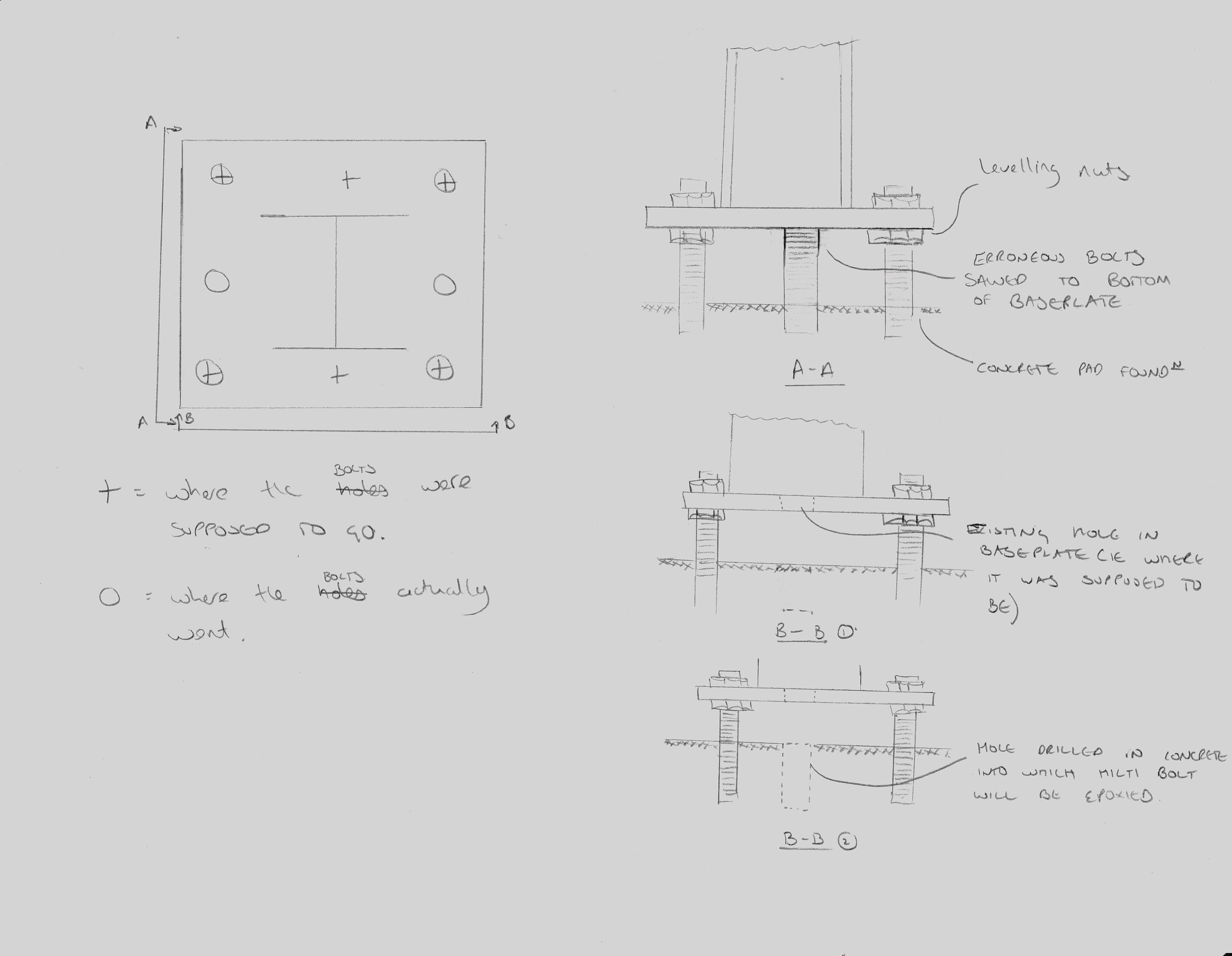
Sketch of Baseplate anchor rod correction
The washers used at the base plate location also need replacing with larger ones so that they entirely cover the drilled holes in the base plate. This will allow any uplift forces to be properly distributed to the baseplate through the entirety of the washer.
A more serious problem arose at the placement of a double bolted connection. A double bolted connection is essentially a shared connection between two beams on opposite sides of a single column. This is a fairly common connection type however the method of erection is supposed to be controlled for safety reasons. This is stated by the Occupational Safety and Health Administration (OSHA) para 1926.756 and also in the USACE HQ document EM385-1-1 at OSHA and EM385-1-1 (Cl 27 E)
Erection in a manner contrary to these documents is essentially illegal so in order to prevent the issue correct erection methods are stipulated in the contract documentation (spec) and checked for in the steel erection plan submittal which is required by the government before work can start. In cases where shared connections exist there are three standard ways of staying compliant with the regulations. These are sketched (crudely) below but are 1. Cut outs in the end plate. 2. Staggered end plates. 3. Welded or bolted shop or field attached seats. These methods are designed to either support the first beam directly or by allowing the minimum single snug type nut and bolt to remain in place whilst the second beam is flown into position. This removes the risk of the first beam slipping its connection and falling during the process.
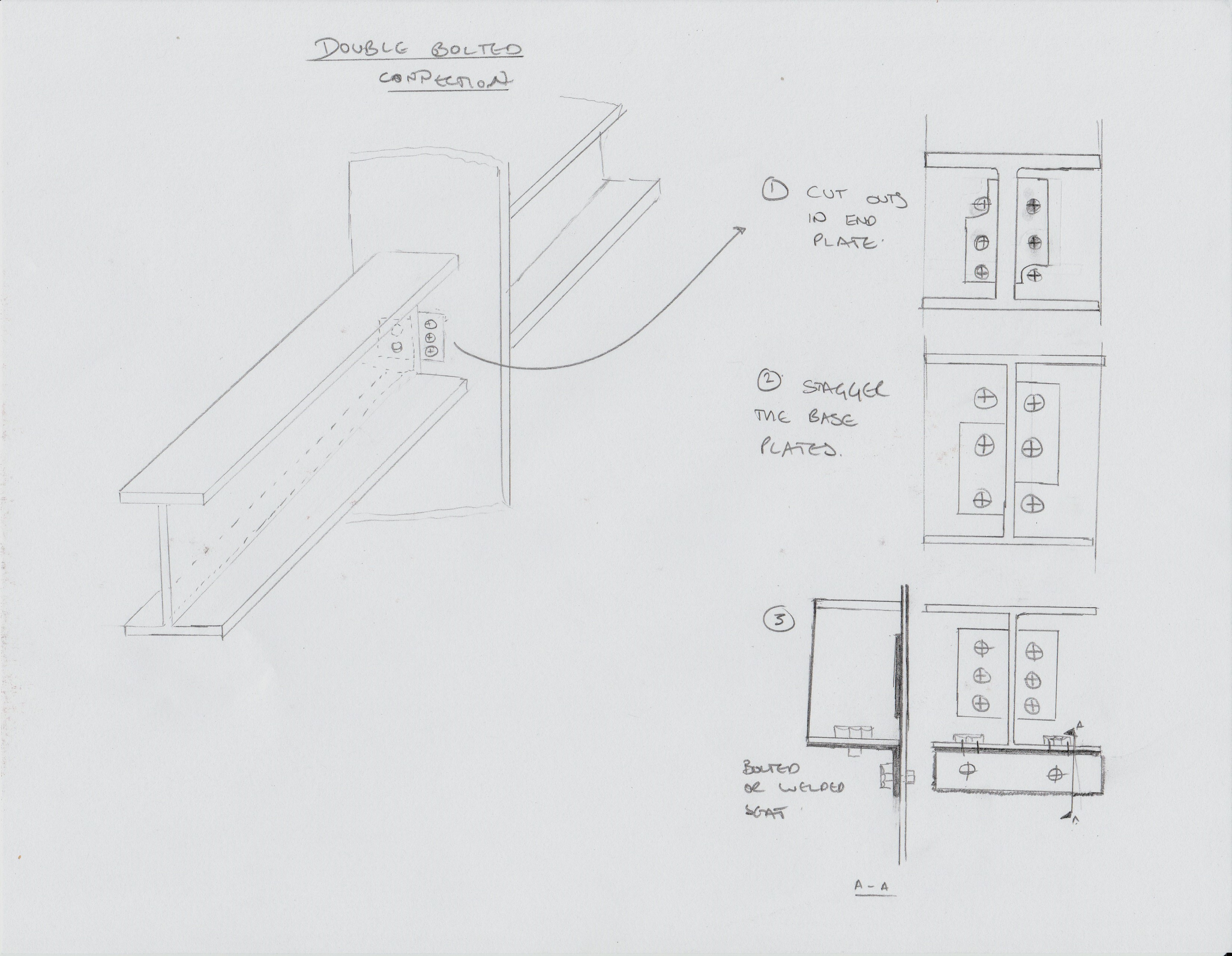
3 methods of fabricating for double connections
On site the majority of the shared connections are staggered (pic 2) to allow for this method of erection, however some have neither a cut out in the end plate or staggered base plates. When asked exactly how he had placed the beams the subbie admitted that he had removed the nut which had been placed after the first beam had been flown in and one of his lads had stuck his spud wrench through one of the other bolt holes. Highly naughty. We chatted about the situation for a while and figured that there must have been some sort of detailing error because it made no sense to not stagger the connection plates, and even less to not detail a factory fitted seat. Since he was the sub contractor I am not supposed to give him direction, unless it is an imminent safety issue, so I had to speak with my counterpart at the Principal Contractor in order to resolve the issue.
I went back to the office and was able to corner the resident steel expert who pointed me to the US American Welding Society document D1.1. This thrilling tome has within its many many pages a calculation for the strength of a fillet weld which is basically a function of the area of the weld and the grade of steel of the rod that is used during welding, with a factor of safety thrown in. I was able to assess from the field drawings what the heaviest beam would be in the whole construction and based my calculations on this. I proposed a 1” x ¼ “ fillet weld which could be applied in the field to the first beam that was flown in. This would be more than sufficient to hold the beam in place whilst the nut was removed in order to fly in the second beam. Obviously my proposal was only a recommendation and the actual design would need to come from the Principal Contractor. I highlighted this to them and requested that they submit an RFI for the field solution so that an audit trail would exist.
My proposal was questioned with an air of refusal by my counterpart who said that she had spoken to her manager who didn’t see the problem. A quick scan through the necessary paperwork, including EM385, the Specs and the Steel Erection Plan and a face to face with some relevant paragraphs printed out highlighted the government’s position. The issue remains unresolved as we wait for the RFI but the last I heard the Health and Safety guy had waded in and written a deficiency. This takes the issue in a more ‘formal’ direction which I had been trying to avoid.
Incidentally – I tried to find a similar clause in CDM but didn’t get on so well. Does anybody else know if there is one / where it is?
In other news – my wife and I went on a road trip to Niagara falls. Wetter than an otters pocket.

I also navigated one of the more arduous ‘trails’ in typical local attire fuelled by suitable amounts of coffee.

Standard US hiking Garb

Brad – in priority order:
Nice baseball cap – you are pretty much now an American!
Drawings – wow you have upped your game, the days of Ex Bridge are clearly well behind you now.
Fabrication questions – I cannot work out what your column between the 2 beams is. It looks like a flat plate? If the column was orientated such that the beams connect to the column flanges (rather than web) then the connection might be simpler? Clearly that depends on the way the column is supposed to be acting but I would have thought it would be with beam attached to flanges rather than the web?
The issue we have on site with welded connections is the requirement to have a qualified person do it and more importantly check and sign it off – i.e. quality assurance, hot works, working at height, cleanliness or steel, screens, PPE, the list goes on. There does not seem to be the same issue with bolted connections.
Finally, if there are lots more of these beams and columns to erect, perhaps a factory welded plate onto the column to allow the beam to join to it might be useful. Access issues to the bolts need to be looked at as well…
Damo – Thanks for the comments! I’ve sketched the flatplate to highlight the issue, here on site the two beams are connected to a column. You are correct that the orientation of the column is a factor but, yes, the issue we are having here is due to both beams being flown in to a column web. Actually, thats an incorrect statement, the issue is that the connection plates aren’t oriented in one of the two configurations above nor is there a seat fitted.
You are correct also that site welds are a bit of a nuisance for all of the reasons you mention above. The proposal put forwards is a field solution in order to expedite the solution so as to minimise the impact on the schedule. The same team that is building my Chiller is also going to be erecting a much more complex structure elsewhere on site and using this fairly simple structure as a bit of a rehearsal. As well as the RFI i proposed for the field fix i also highly recommended that the contractor should look for any other locations where this issue may exist (firstly in future Chiller sequences, secondly in the future truss erection) and look at getting factory fitted seats attached or attach seats while the columns are still in the storage area on the ground.
Yes American connections have always been a bit strange , like the fish-plate (L) sections you show. One way in the UK is the fin plate , it avoids common bolts but you only get double shear. Usually in the UK this connection will be for secondary beams ( as Damain points out, they are on the weak axis) There will often be a part height endplate welded to the beam on both sides. We don’t usually bugger about with offsets and do usually part bolt and remove nuts on the other use a podger I have seen temporary seatinh (L) cleats welded on the initial side but I assume that the steel would be netted and if the bolt group were lost; that as long as the connection on the other end was completed there would be sufficinet moment connection ( in a non moment connection ) to save the beam form doing much harm
There is an FPE advantage in deliberately introducing shelf angle catch plates, which we might discuss on phase 4.