Sundrop Farms Project Update
This blog aims to provide an update on site progress, as well as demonstrating the wide range of tasks that seem to land on your lap as an engineer. Apologies if it is a bit long, not had a lot of time recently to blog.
My main area of responsibility (the pipeline) is nearing completion, with the filling for the hydrostatic testing taking place as I type, should take around 3.8 days. My involvement in this has been limited to developing the test procedure alongside the subcontractor and client, as well as ensuring the relevant standards are followed and John Holland isolation procedures are adhered to. It did however give me the opportunity to wheel out some P=ƿgh action when the client asked why we were not going up to the full test pressure (answer – because the pressure gauges are not at the lowest point). Other areas I have recently taken on include the intake and outflow at both the sea and project end, as well as the lining of the lagoon structures and all the associated pipework.
The intake and outflow for the pipeline at the sea end is a $1m package of work which has recently been awarded to Guidera O’Connor. I have been responsible for developing the scope of works, getting the designs to IFC stage, introducing the subcontractor to the project and on boarding their construction team. The design currently ties in with existing infrastructure at Alinta power station. A few weeks ago the power station announced its closure in 2016; previously this was due to be in 2030. This clearly has some major impacts on our project:
- Firstly the site is to be returned to the condition it was prior to the power station, including the inlet channel that we are building on and the control rooms that we were going to use for power. Currently this has been passed back to the Client to come up with a solution through negotiations with the land owner.
- Secondly the Environmental Protection Authority sign off for the brine discharge from our site was based on the outflow of the power station for diluting and mixing, prior to the water entering the sea. Further models are now in development by the University of New South Wales to analyse the impact.
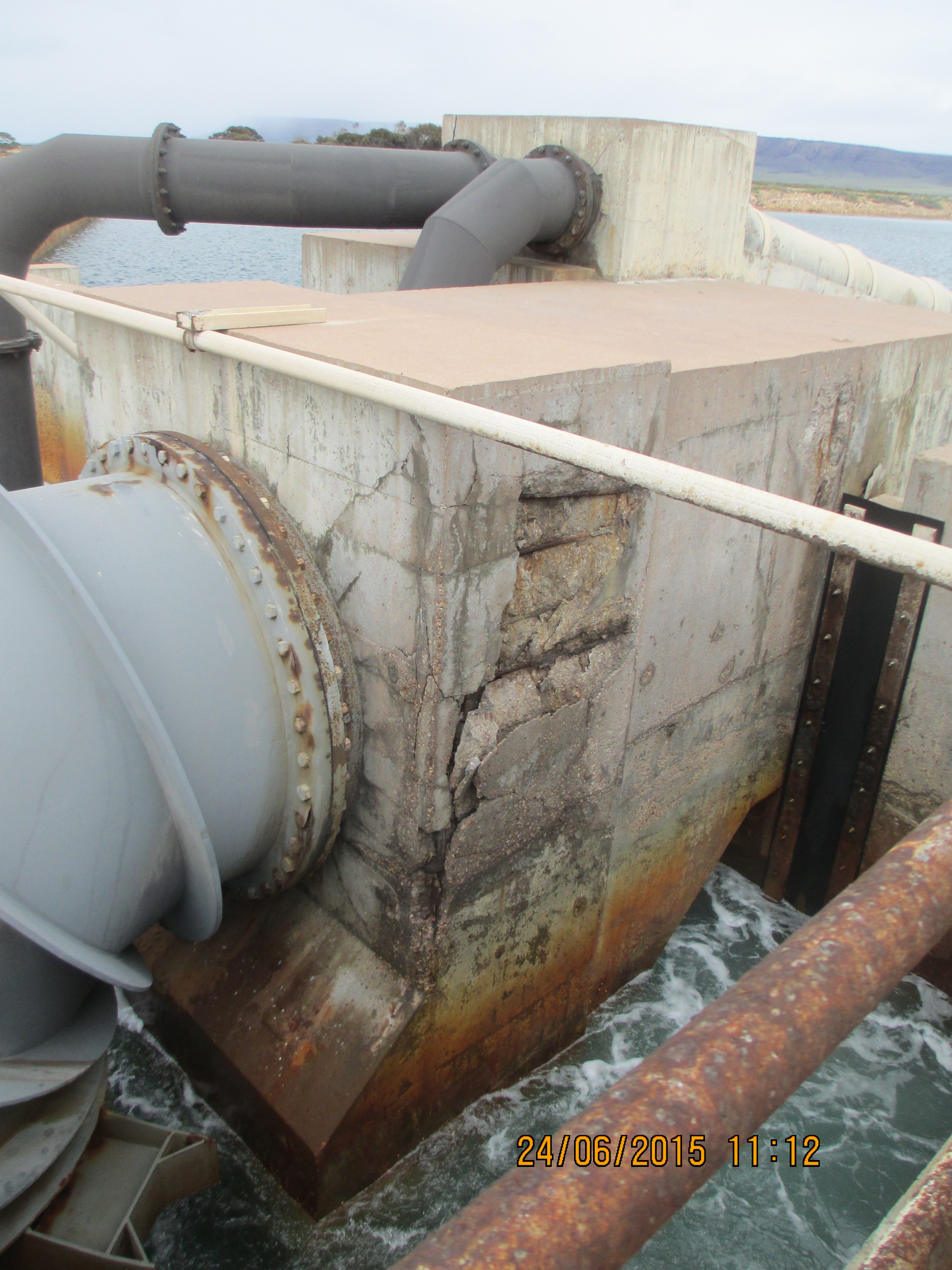
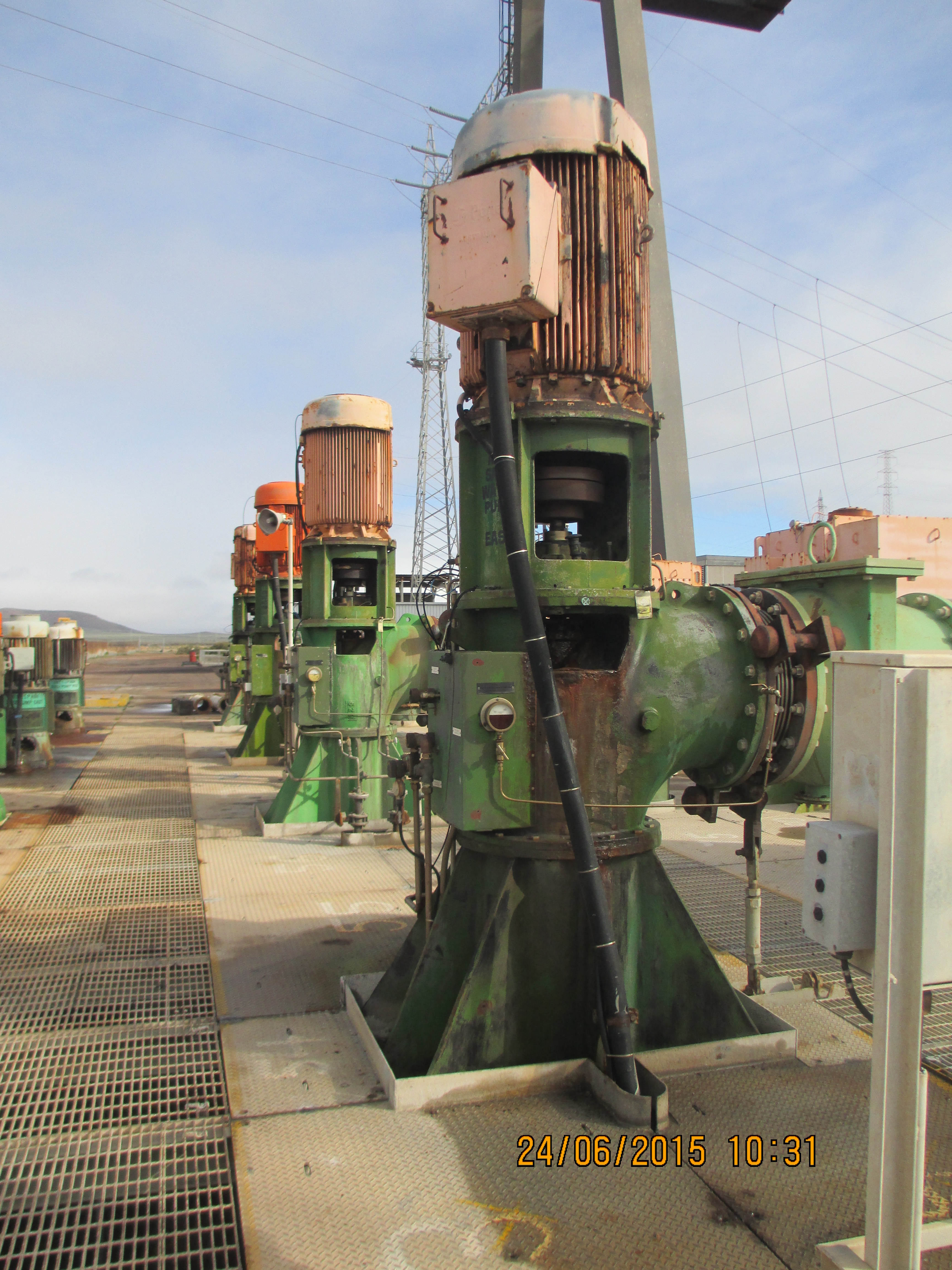
A potential positive is the fact that the government is under pressure to do something about the number of unemployed persons in the area and as a result there are already discussions for a second Sundrop Farm project in the area, clearly this will be dependent on the commercial success of this one. At the moment we have been to soldier on with the current designs, with the hope that the Client comes through in the end otherwise we will have some major variations coming our way. I have included some photos of the existing infra structure firstly to show the state of disrepair that we are expected to link into and secondly to balance the fact that the remainder of this blog is civil based.

The contract for the lining of the ponds was awarded to Fabtech and was valued at $750,000 – at first I thought this would be a relatively pain free scope of work. After interrogating the drawings I discovered a whole can of worms in the form of buried services. Basically I have spent the last two weeks trying to find out who is responsible for what services, taking items out of various scopes of works and awarding variations to Fabtech in order to progress works as they are already onsite and we can’t afford any delays. In the process I have found gaps in both the design and procurement packages, which always makes you popular on site. One of the most surprising gaps at the moment is that there is still no plan for the waste water across the whole site, even though the subcontractor for buried services starts next week.
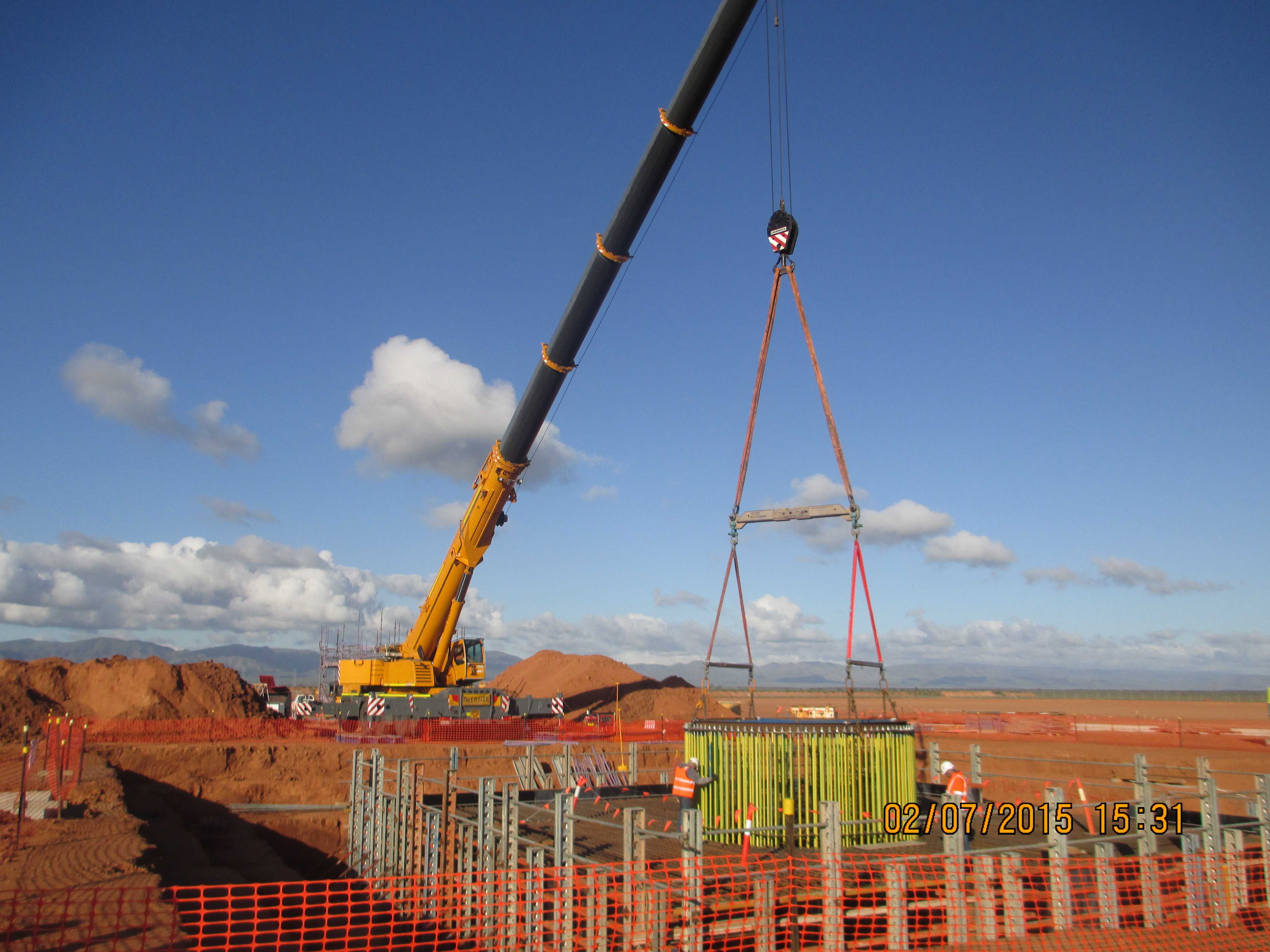
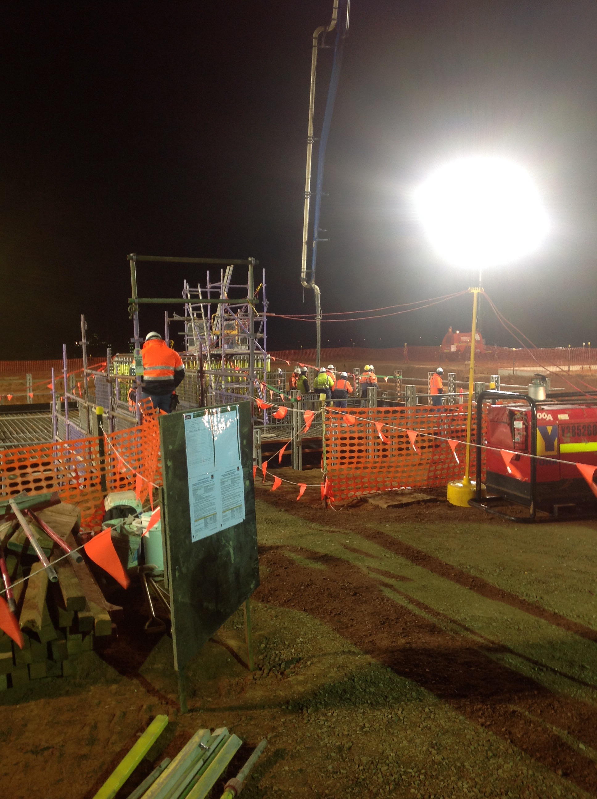
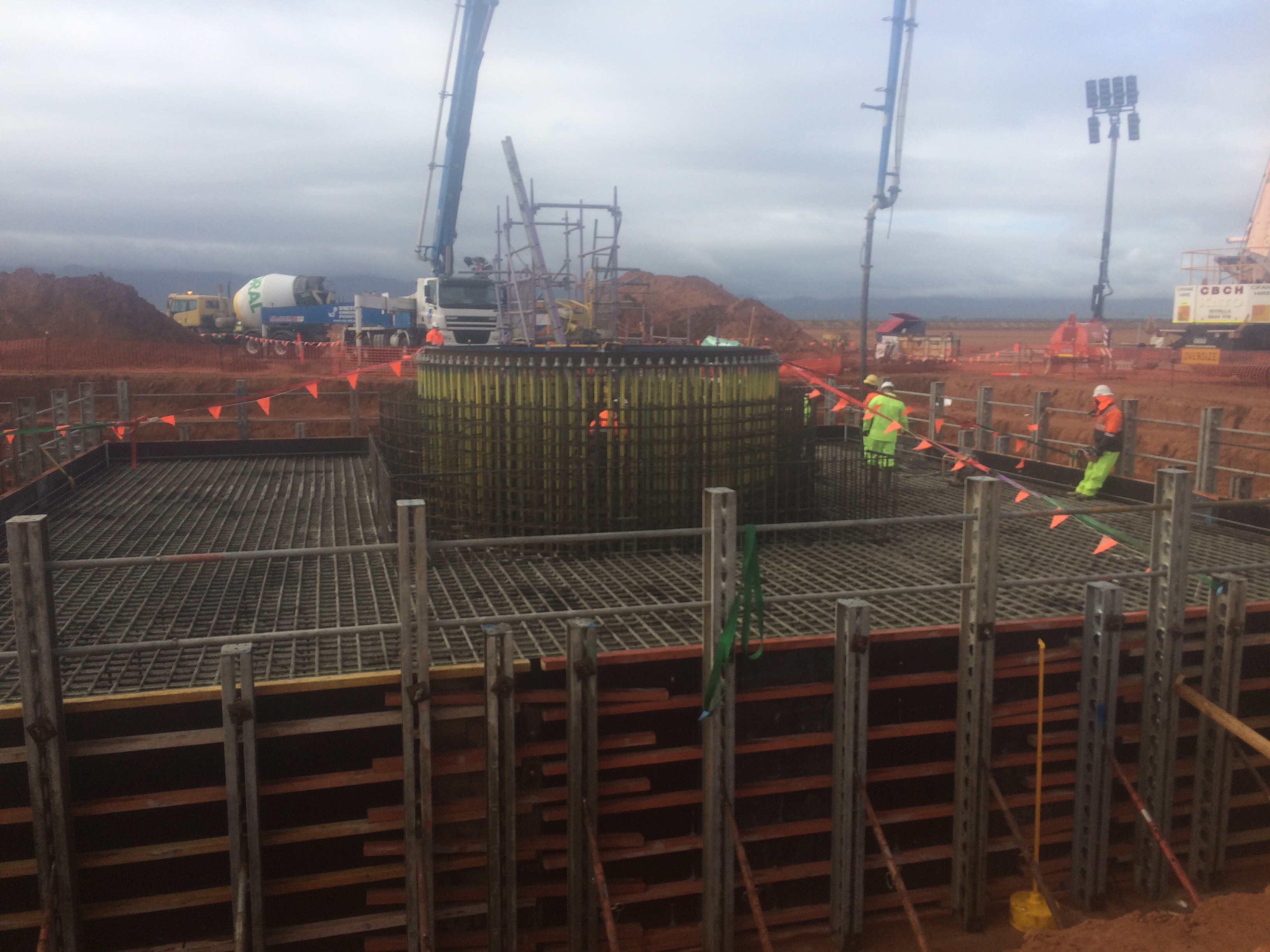
The big recent event on site was the pour of the Solar Tower foundations; I have included some pictures below for all the civil types out there. In total the pour was around 550mᵌ, it began at 0300hrs and lasted until 2000hrs. The planning and preparation involved in the whole pour was quite impressive and was greater than what I witnessed on some military operations, with standby pumps, plants and trucks identified across the state and put on reduced notice to move. Inside the reinforcement you can see the ring of 200 bolts, 4.5m long which will eventually hold the base of the tower. The photo’s below show the template holding the bolts getting lowered in to place, the start of the pour and the end of the pour (yes it is raining).
Other random things I have been running with include dealing with some asbestos that was discovered whilst excavating the pipeline writing an Acid Soil Sulphate (ASS) plan and the redesign the pipeline as it crossed through an area that locally has become known as the ‘bog’. The area in question was a concern as the pipe transitioned from an area of pale brown sand to an area of grey clayey sand before going back to sand. From John Morans lessons the mention of clay clearly sent alarm bells ringing in my head. As a result I was then tasked with organising a geotechnical investigation to try and establish an estimate of the long term settlement (which came back as 50mm over the 100m) and then amend the construction method and design to bridge the gap whilst ensuring there was enough flexibility to prevent the joints from opening up at a later date. All very civil orientated but I suppose it prepares me for future roles as a PQE in the Royal Engineers. What was a shock was the fact that this whole episode came as a surprise to everyone, despite the fact that the area can be clearly seen on Google earth. The photo below shows the result of a test pit, which started out as 1m wide by 3m deep trench about an hour before.
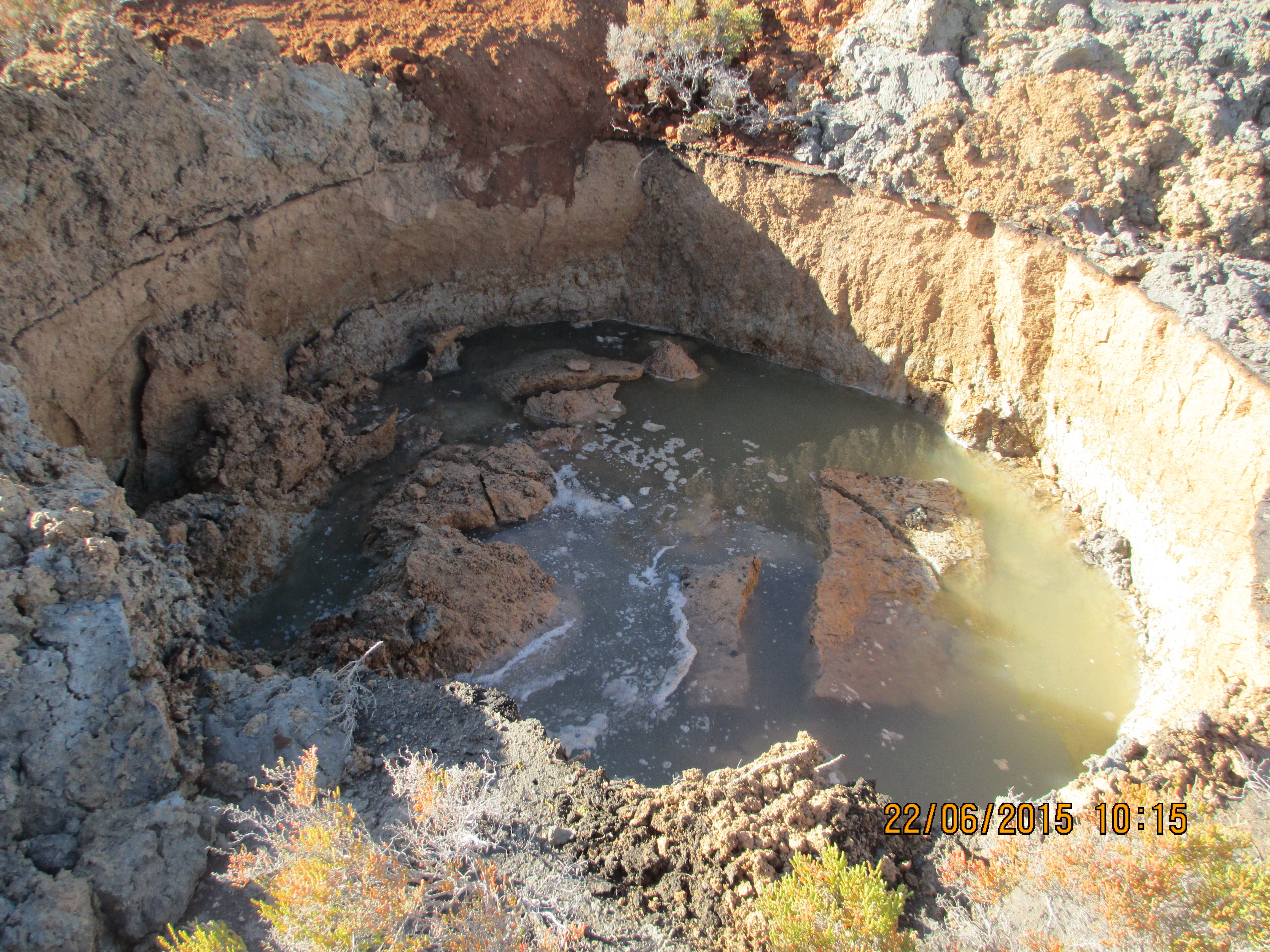

Thanks Matt, You’re so lucky not to be a ‘C’ right now – big crane adjacent to benched excavation? holding down bolts in sleveing? and what is the approx scale of you crater being created by pore water pressure? Hope the ‘C’ community read this blog and reflect on the challenges! Are you working with Uni SW on the brackish water issue? can you get invlovved – I’m guessing it’s a very E&M topic…
Matt, welcome back. Good to see that you are getting a really diverse range of attachment experience. Richard is right, the brackish water dilution with and without the power station could make for an interesting TMR, as it will allow you to discuss the pros and cons of the different mitigation measures.
Will you have to ‘tie in’ to the existing pumps and pipework or will you be feeding into a chamber beforehand? My thought is that with the amount of corrosion this equipment will have seen making any sort of direct connection may damage them. This could cause you to have to chase the issue further into the existing system. This would be a risk for the client as they will clearly have to pay for it; for you therefore would be an opportunity to either get plenty of variation orders or to avoid a direct tie in and gain some brownie points.
Richard, the crater was about 5m in diameter by the time it finished collapsing. The original bore holes results said the water level was at 1.5m, maybe this was at low tide! Unfortunately all the water dilution studies have been organised by the designers (KBR) but as Jim says it would make a interesting TMR and I have already begun looking into it.
Henry generally the infrastructure isn’t to bad, we are installing our own pumps inside the same chamber as the existing ones. Recently I have proposed a number of design changes to enable the construction to be carried out in a safer manner i.e. not in a potential confined space, 10m above water, next to the power station intake which can’t be turned off. (Sounds like the glass fronted orphanage scenario from the bombs course). Nobody want’s to entertain the idea of building our own infra structure down there, I don’t think the client would be able to foot the bill!
Matt – Very interesting blog! Clearly I will move straight towards the civils part regarding the foundation pour.
Formwork. First observation is the formwork design for the circa 2m high foundation pour. It appears the formwork is attached to the reinforcement cage at the bottom and top with a pretty flimsy looking angled prop mid-way up the soldier. Noting the height of the pour (2m ish) and 17hrs for it that is a 0.1m/hr rate of rise so I suspect that was so painstakingly slow to avoid hydrostatic pressure on the shutters and to reduce heat of hydration and cracking issues with such as high mass pour.
Concrete mix design. Do you know if there were any admixtures used to slow the curing down to allow for such a long pour time? Any chance of seeing the mix design? What was the maximum daytime temperature?
Bolts. Richard – is it not pretty standard practice to “cone” around holding down bolts to allow give to fit the incoming structure over them – otherwise trying to achieve mm tolerance normally ends in pain. Post grouting to backfill the voids.
Confined space. Matt – what was the escape plan for the steel fixer within the bolt group should he have a heart attack – looks like the ladder in the background it not going into the ring of bolts?
Pile mat. It looks like the crane is 100 tonne plus – what ground bearing pressure was the outrigger designed on? Looks like a pretty tiny piling mat so I assume this is some sort of sand stone as oppose to sand?
Damo,
The flimsy props you mention are short turnbuckle props rated at around 55kN in compression, these were held in place by bolts into the blinding which was thickened to 300mm to accommodate them. The pour happened at a rate of about 0.1m/hr but this was a limitation of supply of the concrete to site rather than hydrostatic pressure, the designers believe that the rate could have been doubled and still be within permissible loads on the formwork.
With regards to the concrete itself this it was a low heat mix, S40B, 20mm aggregate with a 100mm slump with tests taken for every 50m³ poured. Not sure what the predicted max day time temperature was, however from the photos you can see it was well below the 27°C specified as the limit for this type of pour in the KBR specification, which I think is taken directly from AS 1379. In addition insulation was placed on exposed surfaces of the concrete to try ensure uniform curing, with the form work itself providing the rest.
The bolts are a sensitive subject in the office at the moment. The manufacturers of the tower Ottoway Engineering supplied two template rings for the top and bottom of the bolts, York Civil (the company doing the foundation) got a them to manufacture a third template, which was used at the mid point. The whole template was assembled on site checked by York surveyor then moved into position and checked again by surveyors from both John Holland and KBR (designers) prior to the pour and was deemed to be within tolerance (+/-2mm). After the pour a John Holland got a surveyor back in, they surveyed the flange at Ottoway workshop and then the top of the bolts. The results showed that a about 50 (25%) of the bolts would clash with the flange, the majority within 1 to 2mm, however 15 of them would clash by up to 6mm. YK are now in a position to pour the second part of the foundation, a 100m³ pedestal that sits on top. Currently we are working on how to move forward – the proposed method is to remove the top template and get the flange from Ottoway and use that instead, hopefully allowing the bolts to be adjusted sufficiently. The flange would then need to be removed and sent back to the workshop for the first section of the tower to be welded on.
Access wise during the build of the form work and reinforcement access was via a ramp in to the base of the excavation. A temporary scaffold structure was used to make a walkway from ground level via a stair case on to the top of the reinforcement. A further standalone scaffold tower was then used to provide access into the ring itself, with access via a ladder on each side.
The site is generally made up of sandy clay, with a ground bearing pressure of >500kPa therefore no matting was required.
Matt – thanks for the comprehensive reply. Interesting to hear about the bolt and flange clashes. From my, albeit limited, experience it almost always seems sensible to post drill bolts, or plunge steel sufficiently fabricated to avoid connection issues. The idea of putting tonnes on m3 of concrete in and around bolts or other steel, even using templates, and then expect everything to line up frequently seems to fail. I would be keen to know how the problem is resolved. I know it is not E&M specific but useful to know how these problems are solved!
No problem, writing it up on here helps me get a better understanding of the whole problem as well. The pour is currently scheduled for this Tuesday so will update you after that.