A Quarry Conundrum..
1. Project Update. In order to raise the Earth and Rock-filled Embankment dam here at Chaffey Reservoir, a reinforced earth wall (RE Wall) is currently being installed along the existing crest of the original dam (broadly speaking). As the engineer responsible for raising the dam crest, the RE Wall installation falls firmly within my remit. The works have been subcontracted to Fusion Civil Pty, an established earthworks company specialising in such structures. However, aside from the considerable size (500m x 7.5m x7.22m), it is the fact that the earth core is composed of three very differently graded aggregates, vertically aligned into three specific zones that makes this particular RE Wall quite unusual. Such a design has been adopted in order to control the rate of seepage whist preventing any water being visible on the downstream face. The zoned fill technique has also been adopted within the existing embankment dam below, however this also has rock armour installed on both the upstream and downstream external gradients. The primary impact of having zoned fill material within the RE Wall is the slower rate of construction; a fact that Fusion Civil are currently discovering to their cost (quite literally).
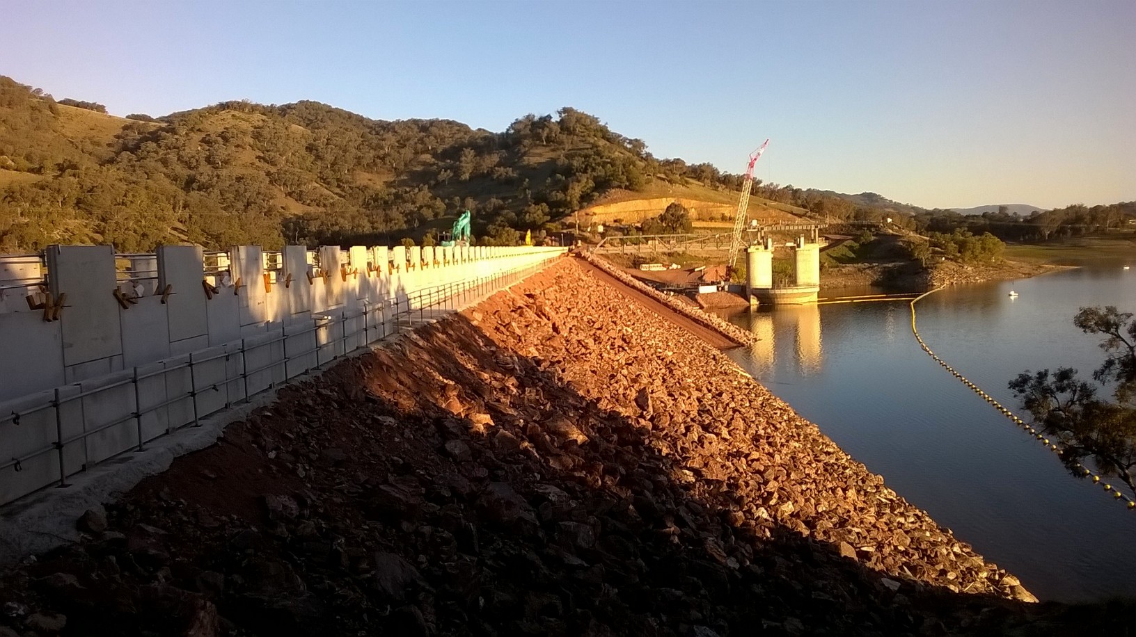
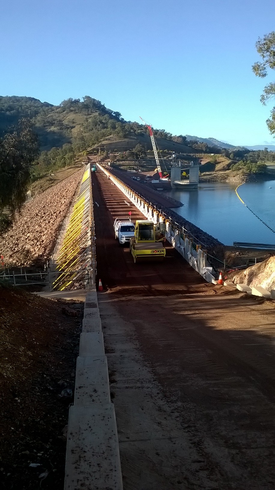
Chaffey Dam & RE Wall Upstream Face
2. Quarry. As well as being the engineer responsible for raising Chaffey Dam I also manage the on-site quarry which includes the sourcing, screening and crushing, load/ haul and all associated QA. A great benefit of the location here at Chaffey Reservoir is the local geology, perfectly lending itself to an on-site quarry for the both RE Wall Fill and road base material. Whilst it may sound to be a fulfilling and interesting role, the quarry has been the source of great frustration and angst since day one. Primarily, this is due the ‘cheggars’ subcontractor that John Holland selected to conduct all crushing and screening of the raw material. More to follow…
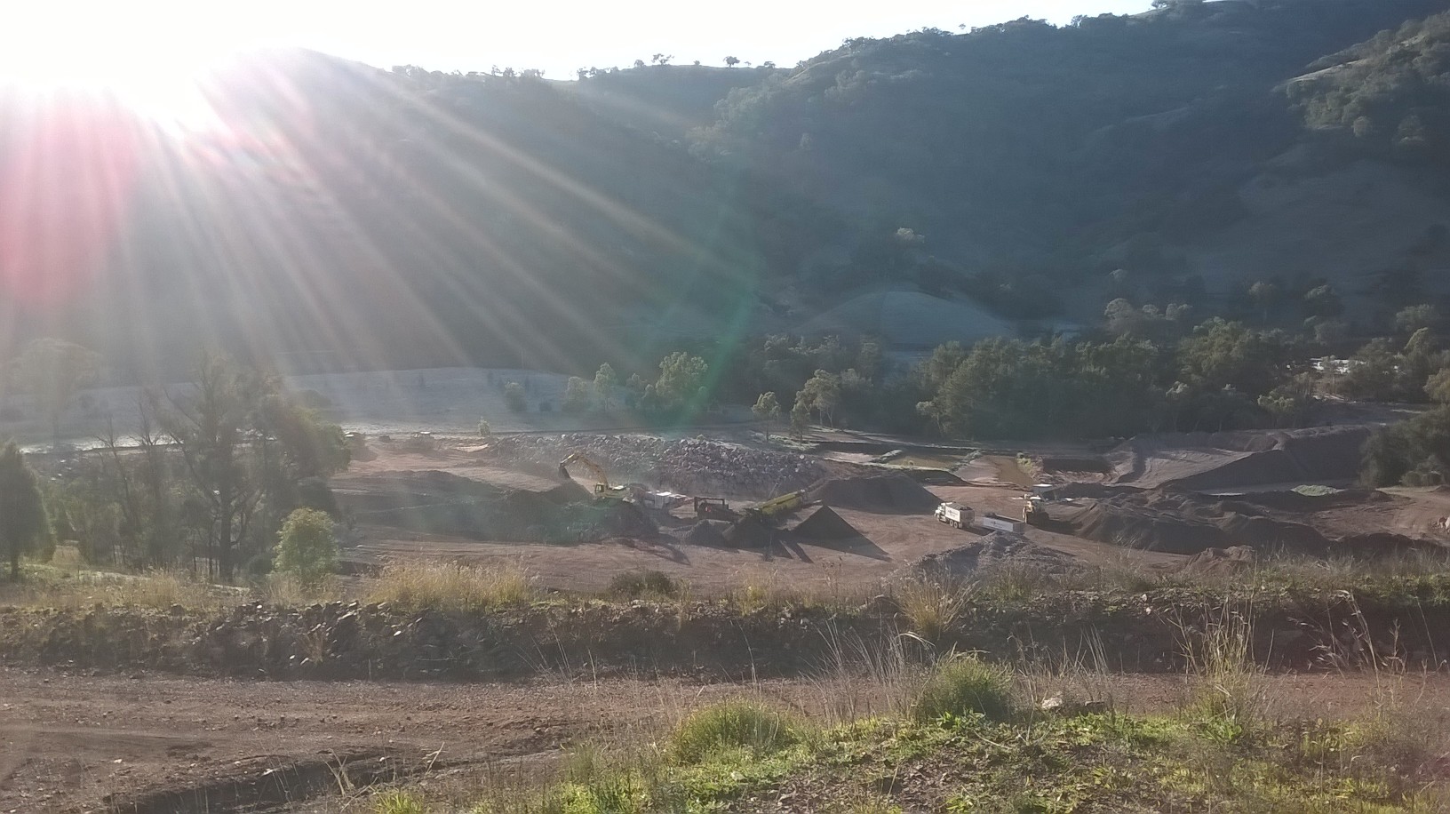
Chaffey Dam On-site Quarry
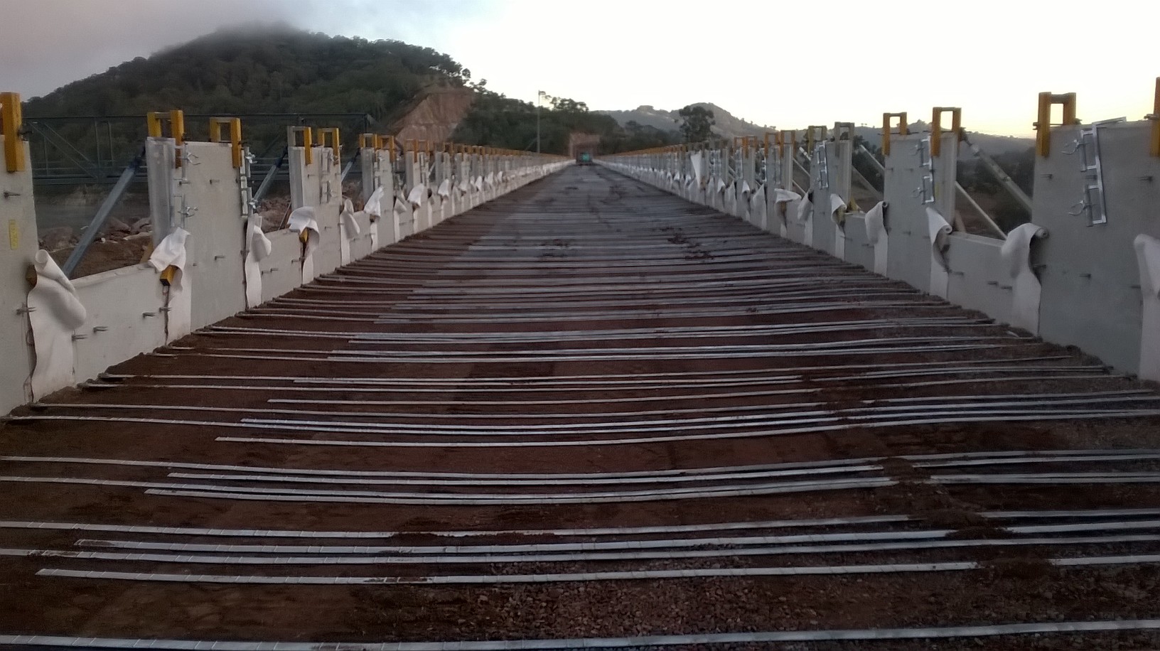
3. At present the RE Wall has had six 0.3m layers of fill and three staggered layers of 2m high precast concrete wall panels. Each 0.3m layer of fill material is hauled up to the crest from the quarry (≈1.1km), placed by a single CAT 730 articulated dump truck (due to with restrictions) before being spread and finally compacted by Fusion Civil. Once 50% of a layer has been placed and compacted I request that compaction is checked. A local Geotechnical firm provided the material technician who then determines the densities of the in-situ material using a nuclear densitometer. For QA purposes I chose to divide each layer of fill (≈ 950m3 aggregate) into two work lots (chainages 0-250m and 250 – 481m) based upon work lot sizing guidance within Australian standards (Roads & Maritime Services Q6). Finally the layer is strapped with the reinforcing galvanised steel straps as shown in Fig 2. Remarkably, it is the steel strapping that provides the structural integrity of the RE Wall. The straps provide the tensile strength that holds the precast concrete panels in position simply from the vertical load imposed by the compacted earth layers.
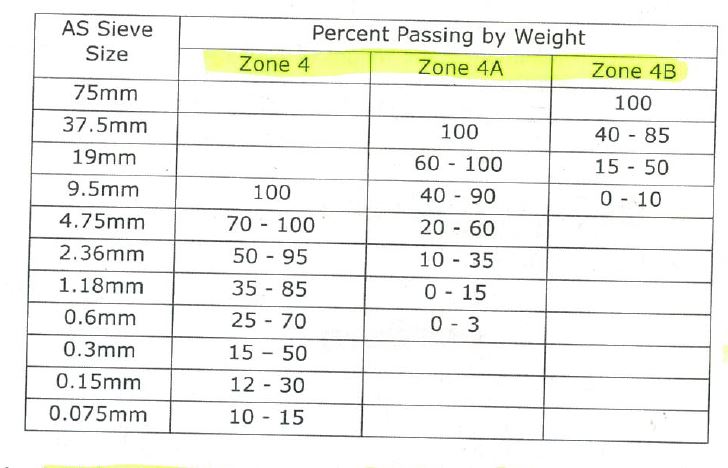
4. Volcanic Resources Pty are the subcontractor who are responsible for all crushing and screening of raw materials. Their primary function is to produce the correctly graded material as specified within the principle contract (CDASU GC21). The three materials are categorised as zone 4, 4a and 4b and increase in aggregate size respectively. Zone 4 material is the initial material located in the zone closest to the upstream internal face of the RE Wall in a 2m wide strip running the length of the wall. It has the lowest permeability of the three fill materials and is a reddish/ brown, well graded, angular, silty SAND. Zone 4a is the next material located in the centre 2m strip of the RE Wall. It is also reddish brown in colour and well graded but is a sandy GRAVEL that is designed to allow water through at a greater rate whilst providing structural integrity within the earth core. Finally, is the zone 4B material. It is placed in a 3.2m wide strip between the centre and downstream internal face of the RE Wall. It is a grey, poorly graded, angular, gravelly COBBLE that is designed to be highly permeable whilst providing structural integrity. Due to the high voids ratio water is able to pass freely and is a requirement as it is intended to prevent water ever reaching the very large rock armour on the downstream face of the Embankment dam. The idea being that if the public were ever to see signs of water penetration on the downstream face of the dam, panic would ensue.
5. Material Conformance. The latest issue has been one of material conformance. Until recently, Volcanic Resources produced all fill material simply using an industrial rock crusher and a mechanical screen. The machinery was set up to produce all three required products concurrently
( 4, 4a and 4B.) However, approximately five weeks ago the large zone 4B material was no longer required as I determined that the stockpiled volumes met the estimated demands for the remainder of the project. Despite this, the 4B material continued to be produced as an unwanted bi-product at a considerable rate. At this time, half way through the project, the subcontractor demanded that material prices were renegotiated due to the sudden reduction in his earnings. JH politely refused yet were unsurprised by the request due to previous grievances raised by the subcontractor. The subcontractor subsequently request that JH purchased a cone crusher, in addition to their own crushing machine. The idea was sold to JH under the guise that all the oversize waste material could then be re-processed, saving JH the need to excavate and haul further raw material. An agreement was reached whereby by JH agreed to hire a cone crusher up to a limit of $45 K (AUD) after which time Volcanic Resources would assume the financial hire costs of the machine.
So What?
7. Upon receiving the shiny cone crusher, material production rocketed and waste material stockpiles quickly diminished; a relief for me as the zone 4 stockpile was shrinking faster that it was being replenished. However, all was not well. Upon inspecting the material produced, it was apparent that there were distinct differences between the “pre” and “post” cone crusher zone 4 and 4A materials. The zone 4 material appeared overly coarse and failed to bind when moulded. Equally, the previously well graded zone 4A material was now very clean, uniformly graded gravel (perfect for a drive way NOT an RE Wall..). I immediately interrogated the Volcanic production staff on how they verified that they were producing conforming material (As the owner had already reassured me all was well). They simply said there were given a maximum aggregate size for each material and that was it…
8. 48 Hours later and the results confirmed the my concerns. Overly coarse zone 4 material and a uniform 4A material lacking sufficient fines to meet conformance. Fortunately the material had not entered the wall. Unfortunately, the material had contaminated existing stockpiles (but was fairly straight forward to identify and separate).
Lessons Learnt.
9. Do not trust a subcontractors’ word without checking, even if they are contractually obliged to make the product. Do not assume the obvious has been done; Common sense would say that as a material production specialist (i.e Volcanic Resources), if you change anything in a system you would re-test the new material to check for conformance. Clearly this was not done and they simply did not care. When I confronted the owner of Volcanic on the issue I was met with the following response:
“If you want your material to pass, why not test a stockpile that you know will pass?”….

Fill Material Production
10. Since this time, they have struggled to produce conforming material. The cone crusher failed to deliver what was promised and despite clear direction, they have attempted to load failing belt material directly in supply of the RE Wall. Much of my time is now spent in the quarry..
Solution.
11. I directed that we reverted to using predominantly raw feed (high % fines) with a blend of the oversize waste product. Whilst better, the material was still struggling to pass due to a lack of fines. As the ambient temperature has recently risen considerably, I directed that the raw feed stockpile was saturated in an attempt to bind the fines with the larger rock. This had an immediate positive impact and produced conforming material. However, the SPE was not overly happy as JH pay per tonnage and do not wish to pay for hauling water. My dilemma was, do I delay Fusion Civil in the production of the RE Wall due to lack of fill material or pay for the haulage of water?… The saga continues…
Reinforced Earth Wall – Left Abutment

Hi Dan, sounds like you are at the front end of the QA process to ensure the wall meets the specification. Does the specification require the work to be done my method or outcome? If you specify a method of compaction which achieves the desired density, is there need to do the nuclear density tests throughout the task? What happens if you have specified method and it does not achieve the desired result?
What are the contractual arrangements between John Holland and Fusion? Are they (Fusion) required to supply and install, therefore does material risk sit with the subcontractor? If so can you adopt some sort of sieve test to determine whether the ‘earth’ is acceptable, if not it gets rejected and it is up to them to sort out?
The steel straps providing tension resistance – is this in the temporary case only? I presume when the dam is raised only one side will need to act in tension? It looks like they do not attach to the other side of the wall – is the weight of the earth above sufficient to provide the required frictional resistance? Was there any consideration of other methods (geogrid for example)? Are there any design life issues using steel in the straps or are they waterproofed?
All sounds good and the scenery looks a lot nicer than central London!
Hi there Damo, cheers for the feedback. Firstly, many congratulation on the obvious!! I hope all is going well. Secondly, sorry it is not a safety focused blog…one will follow soon. I’ll try answer your questions in order.
1. In regards to the methodology it is not entirely straight forward. The principle contract states that the material is to adhere to the Roads and Maritime Services(RMS) standards, i.e. the standards as used on public roads in Australia. So effectively, the methodology is outcome based as specific densities must be achieved within each material.
However, prior to the placement of any material, I lead compaction trials. All three material types were set out in a 0.3m x 10m x 3m layer. The materials were then compacted using both a vibrating plate compactor and a 20T vibrating roller (over different sections) in order to determine the minimum number of passes required to achieved the specified compaction. After each pass the densities and moisture content were recorded/ sampled. In the fine grain zone 4 material the nuclear densitometer was able to be used whereas in the coarse grain material (zone 4A and 4B) the presence of large voids meant that a sand replacement method was used.
In summary it was concluded that both the zone 4a and 4b would be placed and compacted based on results from the trial, whereas the zone 4 (fine grain) would be tested in-situ within each layer/ work lot as dictated by the RMS standards. Despite the results, I still conducted density testing on each material within each worklot (1/2 layer). It was found that achieving the mandated densities was actually more difficult in-situ. I concluded that this was due to a less stiff foundation and therefore modified the original compaction procedure to suit. Eventually, due to consistent results I reduced the frequency of testing on the 4a and 4b material.
2. Fusion are employed on a lump sum contract which is why the slower than forecast production rate is hitting them hard. They are purely required to install the RE Wall. It is my (Volcanics…) responsibility to ensure that all material supplied conforms. Whilst JH employ Volcanic to produce conforming material (grading) I must ensure the electro-chemical standards are also met as well as the in-situ density (that risk lies firmly with JH).
3. in regards to the steel straps, there are required to have a minimum of 3mm gal coating and may only be tracked by rubber wheeled vehicles. The client was suspicious of the long term durability and requested a trial to see the effects of tracked vehicles/ rollers passing over them. Fortunately the galvanised coated remained unscathed. In regards to their durability the electro-chemical test are important. The presence of chlorides and sulphates soundness was of particular interest to the client.
4. Structurally, the RE Wall relies upon the frictional resistance created between the soil and the steel straps. As such, I expected a heavily ridged surface along the straps but they have approximately one small ridge every 300mm along their length. During construction the wall panels are tilted inwards (5.5mm per vertical meter). Once the material is then placed and compacted the wall panels become vertical and the tension is developed equally across all straps.
Sorry for the extensive reply but hopefully this makes things some what clear. It is slowly getting hotter now and the dam Brown Snakes are starting to appear. I gave a toolbox chat at the pre-start daily meeting to all the workers warning on the dangers of snakes and the actions on should they get tagged.. funny as hell briefing Aussies on the dangers of snakes!!!
Interesting… Reading betwen the lines I think you are saying:
Material processing is by Volcanics on a specification basis for grading. JH therefore monitor for mechanical compliance. JH hold and retain the risk of electro-chemical conformance because they source the material through provision of the on site quarry. This would seem to keep risk in the most appropriate place for managing it. Presumably failure of mechanical criteria costs rest with Volcanic and they must dispose/re-grade failed material. Failure of electro-chemical criteria is a JH risk and JH would pay for the processing of the load and subsequent disposal. This is all relatively clear. Interesting is the question of which test is applied first. electro-chemical or grading. If a load fails grading is it tested to see if it also fails eectrochemical criteria and if so where do costs fall?
In terms of onsite specification/method and the Fusion contract, it would seem there is a muddying of the waters. JH appear to have specified a final density, which would be sensible if Fusion were then left to decide how to achieve it and QA/QM checked in doing so. However, it would seem JH have started to tell the Fusion how to complete the works or were the trials done by Fusion so that they could decide what to do in order to limit their risk of non compliance? i.e. When you say “it was concluded that… would be placed and compacted based on results…” was this a decision by Fusion as to how they would proceed or is it an instruction from JH on method? Was your ‘modification of the compaction criteria’ given as advice to Fusion to modify thier on site instructions for operatives or was it a contractual instruction regarding method? It looks like thay are delivering to method, which has been modifiied since the contract was signed therby leaving them open to claim equitable adjustment for variation i.e. they are being aslked to do other than that which they have contracted for.
I’ll leave Mr Moran to comment on the ‘tension’ aspect of the straps. and ask you to consider the nature of the failure you think they are preventing…
Good Blog – Welcome back at last!
Just a few comments
The material grading varies and therefore the relationship betwen m.c. and dry density varies
Therefore the compaction spec should vary by zone
If a nuclear density meter is being used the spec is by oucomes and this will be to a margin of optimum density. This gets us a decent density
I’d be interested to know if the compactive effort ( layer thinckness, plant weight and no of passes ) actually varies
In regard the way reinforced earth ‘works’
The straps cut the potential shear plane and, in doing so, provide two components – wot they then? Whatever they are it’s not a tensile resistance
John, I based tensile resistance of the straps if they were acting as anchors holding the ‘retaining wall’ up from lateral earth pressure of the soil. Clearly wrong as that is not what they are doing!
I now see the little grooves in the steel straps which will interact with the soil to help prevent mobilisation of a slip. Effectively the straps act in a similar way to geogrid to prevent the wall seeing any load, or as much as what horizontal earth pressure will be generated in a height of a couple of hundred millimetres (height between layers of straps).
Two components – shear (as slip circle is cut through by the straps) (I would still argue the horizontal shear component puts the straps into tension) and bearing/friction (as the straps must pass beyond the potential slip surface to soil bearing down on top of it to prevent pull out).
Grateful for your answer!