Archive
Offshore at last
Introduction
As you may have guessed, my ‘site phase’ of the course is actually based in an office many miles from any site. Last week I finally got offshore and I was able to assist with the survey of the helideck in readiness for the lighting upgrade project due in feb, assist with the lifeboat survey in readiness for the padeye replacement project in May and ‘get all over’ the 4th and 5th PWRI flowline projects. Below are a few of my thoughts;
Movement and Arrival
Heli is the only way to get to the platform and takes about an hour. I have had to do 3 courses and a medical (including drugs test – I passed) to get this far and familiarisation videos and site inductions are required on arrival, which takes up the rest of the day. Lesson learnt – Don’t assume when crew are mobilised that they are going to achieve anything on the first day. Factor in at least a day or even two before any work can commence.
Understanding of the job
Getting out on site allowed me to fully understand the scope of each project rather than relying on drawings and pictures. Of course this is obvious, but you will be surprised when the last time any of the SPAs actually went offshore. One of the JREs I’m working with has never deployed. This is sometimes obvious in meetings when issues are raised. They will know about the problem and what they have been told, but sometimes don’t understand what that means or asks the ‘so what’ question. Lesson learnt – Mobilise during the design phase to fully understand the scope and also mobilise during construction so you can get hands on. Sam – I will arrange a visit as soon as I can after your arrival (once you’ve done the required courses).
SafeCal
Due to the Life Extension Project I mentioned in the last blog, there are more people required offshore than they have beds for, so there is a need to use Safe Caledonia, a floating hotel. See pic below. This is tethered to the sea bed and connects to the platform via a moving bridge. The platform doesn’t move (much), but the SafeCal does as it floats. This week the movement was so much that the bridge had to be lifted, stranding quite a few on the platform. Lesson learnt – There are many things which can cause delays to a project, this is just one of them.
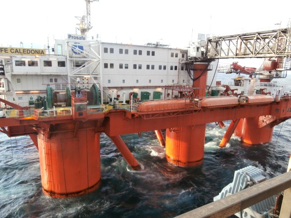
SafeCal – Flotel. Note the bridge connected to the platform.
Heights
This is not a place to be if you are uncomfortable with heights
.
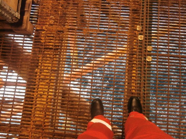
Level 1 looking down
Barriers, Barriers, Barriers
Very hot topic at the moment. As it happed I had two issues with barriers. I was working around the well bay minding my own business. When I went to leave, I came across a barrier that had been erected whilst I was working. I went to find an alternative route but couldn’t because of existing barriers all around; so I was barrier’d in. The second issue was when I went back to the same area 2 hours later, the barrier was still in place even though it was obvious that the reason for the barrier in the first place was now redundant, but meant I couldn’t get into the working area. Pic below – bit of a concern when you don’t know you’re in a working area! Lesson Learnt – Barrier control need work. I completed a couple of BOSS cards. (Behavioural Observation Safety System – used as a method for reporting incidences and encourages discussion at the point of issue)
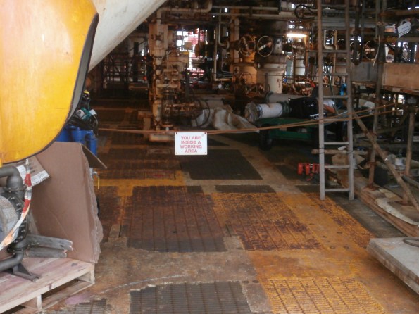
Something just doesn’t feel right
Weather
A platform is very exposed and a combination of wind and rain can make life very unpleasant and stop work altogether if conditions exceed limits. As well as affecting the work on site directly it can also affect the delivery of material from boats, therefore indirectly affecting work on site. Lessons Learnt – Factor in Non Productive Time and make realistic. NPT of up to 45% is sometimes expected.
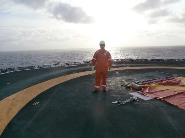
One of the better days. Carrying out recce on helideck.
SIMOPS
The platform is very busy at the moment, as noted by all the barriers!) There is a high risk of delays due to SIMOPS and needs to be managed properly. Even within a single project we had issues. Our original schedule showed electrical work happening at the same time as piping work which involved breaking containment. This was not allowed due to the risk of spark from the elec scope and the potential release of hydrocarbon from the piping work. Lesson learnt – Ensure no SIMOPS clash or deconflict and scrutinise schedules for internal clash.
PWRI Flowline
Below are a few pics to put the flowline in perspective. In an attempt to keep word count in this blog down, see if you can ID where on the schematic the pics refer to. Questions are more than welcome. (subtle differences may be noticed between pics and schematic – ignore)
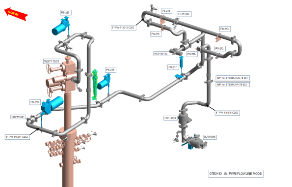
Schematic showing 5th PWRI Flowline

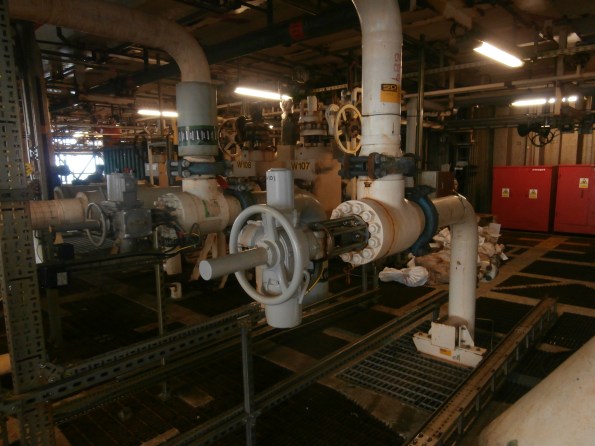
Picture 1
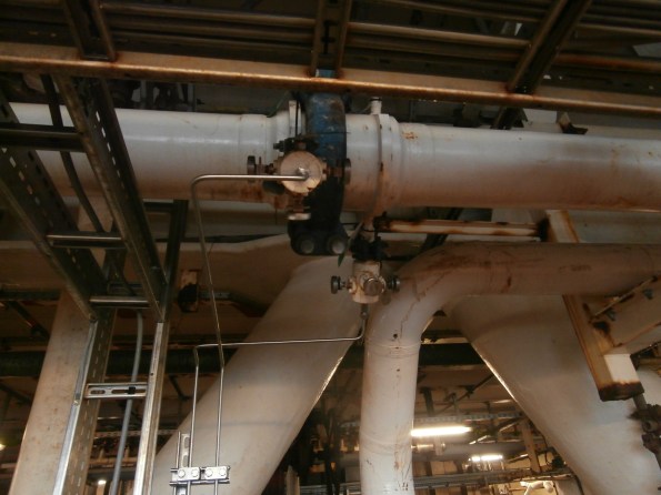
Picture 2
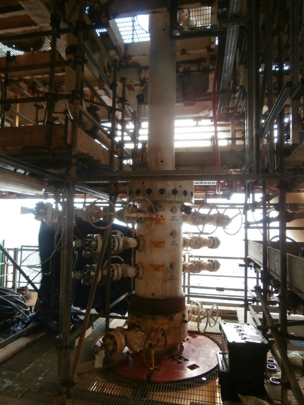
Picture 3

Picture 4

Picture 5

Picture 6

Picture 7
Picture 8
Oz PCH – Commercial and Contractual Tasks.

Example Spectrum Analyser Recording
Introduction
In this blog I will cover various commercial and contractual tasks I have undertaken whilst working alongside the Commercial Team. These tasks came about as a result of my continual DAP review to ensure that I have met as many of the UK-SPEC requirements, at the right level, as possible.
The reason I am conducting these types of task now, compared to the majority of my peers who have done so early-on in their attachments, comes down to timing and project availability. I always knew entering the project at the stage I did meant that the ship had already sailed with regard to the majority of specific contractual stuff. Therefore, through my DAP and in consultation with my line-management I sought out and conducted the following:
RF/EMF Testing Tender Process (B1, B2, C1 and C2)
Here I was responsible for the procurement and tender process for the RF/EMF Testing works package. This was to confirm that previously omitted shielding, via a value engineering exercise, was indeed not required for Electro-encephalo-gram (EEG) recording rooms. An early study conducted by JHG concluded that, based on their needs (not having to architecturally redesign rooms) and the views of various vendors (specialist medical equipment suppliers), the latest technological improvements in medical equipment reduced RF/EMF emissions enough to negate the requirement for shielding. A survey was also conducted of a number of hospital projects nation-wide to confirm what they had implemented in terms of mitigation for RF/EMF emissions.
Why Required?
The client had requested the testing as a ‘belt and braces’ insurance policy, which was absolutely their prerogative especially when you consider the potential implications of the effects that RF/EMF emissions interference can have on critical medical examination equipment. In particular it was the concerns of the client that the EEG recording equipment, conducted by a Neurologist, as the ‘victim’ would see interference from the Evoked Potential/Transcranial Magnetic Simulation (EP/TMS) equipment, the ‘source’, and other potential RF/EMF emitting ‘sources’ such as: the large power motors in the vertical transport lifts, and the standard electrical load running round the department.
The Process
The tender process involved me understanding the procurement options in terms of which type of contract agreement best suited the works to be carried out and the potential budget. Writing the scope of works meant understanding the risks associated with the possible outcome of the testing and therefore ensuring that potential issues were mitigated where practicable. A key risk identified meant that stakeholder engagement was vital to ensure co-ordination of important test conditions where concurrent activates were to take place, including: live EEG testing, minimum 50% electrical power load in the building, specific medical equipment (EP/TMS) being in location and operational and the nearest vertical transport lift in operation. It also included identification of resources required and costs to the project.
There was a fair amount of admin required to prepare the tender packs for seven tenderers (a minimum of three is compulsory as stated in JHG policy) which resulted in only four returning tender submissions. Negotiations over specific scope of works details and costs were had and agreed, forming part of the tender selection process; I liken preparing the RFIs for the tenderers to being handed a planning pack for a Search task on the RESA course, having to ask the right questions in order to draw out answers and make deductions.
The final part of the selection involved a telephone interview with: myself, a Contracts Administrator (CA), the services manager (my boss), and obviously the tenderer. Normally this would have been face-to-face but this particular preferred tenderer was based on the East Coast. Once certain questions relevant to technical and commercial concerns were cleared-up we deliberated over the options before coming to a decision and me writing up the recommendations document which was sent internally for manager and director sign-off. I also completed the Consultants Services Agreement (CSA) form of contract before sending out and sealing the deal via formal notification; this also included non-successful letters being sent.
Implications of Test Failure
If the testing fails, and by fail I mean there is significant interference caused by an electrical source somewhere in the vicinity of the EEG rooms, then a further study will have to take place in trying to mitigate the source. Worst case, the affected rooms may require the shielding that was originally omitted which would not only cost heavily due to having to strip-out a completed room but would also incur a delay. Dependant on how many rooms required shielding, this could possibly affect practical competition but my guess would be partial occupancy at worst but could still attract liquidated damages; currently at $180,000 per day for the entire facility so would most likely be less.
This has all been finalised on my last day working on the project and it’s a shame I won’t get to see how the works package pans out; it being handed over to the services manager to implement in Jan 16.
IC Energy Pty Ltd Works Package Review (B1, B2, B3, C1 and C4)
This consisted of a review of 226 Variation Orders (VO) and associated costs to the Temporary Construction Power & Lighting works package, comparing the original contracted tender costs to that of the current/forecast practical completion costs. I won’t discuss too much of what was found from the review here as I am writing this up as a managerial themed TMR. Suffice to say the original budget increased by 60% (AUD$ 1,374,298) currently at AUD$3,655,109.02 but with the potential to climb to circa AUD$4 million by practical completion. A myriad of managerial and decision making errors attributed to this overspend which the review has brought to light with the intention to be used as an example of lessons learnt for future projects.
Variation Order Claims (C1 and C2)
I reviewed a Variation Order (VO) claim, using the process in figure 1, from Fire Safe Systems who were contracted to provide wet and dry fire suppression site-wide. Under the original contract a number of diagnostic and theatre rooms housing very expensive medical equipment such as: MRI machines, specialised surgical operative tables and the like, were all to be fitted out with pro-inert gas (IG55), using 50% Nitrogen and 50% Argon. The intent being that if in the event of fire it could be suppressed and extinguished using a gas system instead of using a traditional sprinkler system. Thus ensuring any medical equipment not damaged by the fire would also be free from other damage due to using the gas suppression system.
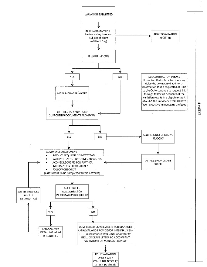
Figure 1. Variation Order Claim Process.
However, the VO came about as a result of the pro-inert gas system design being changed to a pre-action ‘double knock’ sprinkler system. This was due to the design not accounting for the space required to store the quantity and size of gas cylinders along with regular storage and maintenance concerns.
Pre-action systems are hybrids of wet, dry, and deluge systems, depending on the exact system requirement. In this case a double interlock, also known as ‘double knock’ system is used.
The operation of double interlock systems are similar to deluge systems except that automatic sprinklers are used. These systems require that both a ‘preceding’ fire detection event, typically the activation of a heat or smoke detector, and an automatic sprinkler operation take place prior to the ‘action’ of water introduction into the system’s piping. Activation of either the fire detectors or sprinklers alone, without the concurrent operation of the other, will not allow water to enter the piping. With the presence of fire confirmed, water is forced through the piping via a compressor unit but no water enters until a sprinkler operates. Double interlock systems are therefore considered as dry systems in terms of water delivery times. Although not as equipment friendly as the pro-inert gas system, the premise is that the double interlock feature will prohibited false alarm activation and if a fire is present then water damage will most likely be less severe than that caused by fire.
Contractually Fire Safe had to return to JHG the cost associated to the original pro-inert gas system including any testing costs; totalling AUD$ 94,951. This was submitted in the same VO and required a number of RFIs to clarify as the actual figure was never broken out of the original contract sum.
I then reviewed all the costs associated with the new pre-action system, which again required a number of RFIs through emails, phone calls and requesting clarification through marked-up drawings to understand the detail; this amassed to circa AUD$176,000. There were some errors made by Fire Safe in annotating the drawings where they accidently changed the colour coding and nomenclature, which just delayed the review process and JHG trying to do our due diligence.
The lesson here is that all claims need to be justified and substantiated in order to satisfy the Contracts Administrator (CA), or in this case me, to approve payment.
Once the analysis was complete the CA inputted the payment amount into the Project Cost Reporting (PCR) database. I then completed a summary page with the aid of a checklist before submitting to internal JHG managers and directors for their sign-off.
This was then sent to Fire Safe for their agreement and signature of acceptance. This then allowed the CA to update the payment entry within PCR to ‘A’ for approved; it then gets added to the overall project costs.
If the amount is not agreed by the subcontractor then they can take it to dispute but this is seldom done due to the previous communications and negotiations in the initial review process.
One significant difference is when a VO claim submitted by a subcontractor is deemed by JHG to be recoverable from the client. In this case a manager or most likely the project director will hold the payment approval until the client have confirmed they are liable for the cost; a ‘pay when paid’ clause. This is done to prevent the risk of JHG being ‘out of pocket’ for a period of time and used as a delay mechanism, but will still result in the subcontractor being paid eventually; not to be mistaken and different to that of a ‘pay if paid’ clause.
Valuation Payment Claims (C1 and C2)
In order to confirm and approve a typical payment claim, I reviewed one from Fredon (mechanical subcontractor for plantrooms). This consisted of walking round one of the plantrooms with the CA for a visual check to judge the % complete and also as a QA/QC check. We used their payment schedule as the check list and made notes along the way. We then applied a weighting compared to their previous payment and what was outstanding and paid according to that. If there were any major defects identified then this wouldn’t get paid at all until rectified and would roll over to the next month’s payment claim. Similar to the VO process this was then entered into PCR and added to the project.
In Other News
On my return home last night my wife comes out to meet me (something she has never done) and standing clear of the doorway whilst starring round the corner she says “don’t worry but we have an issue”…instantly I’m thinking huge poisonous spider…snake…but no, what do I find cuddled in the corner of the laundry room – two bantam chickens!
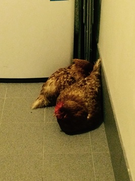
Parting Shot
It just leaves me to say this is my final blog whilst working on the Perth Children’s Hospital project – and what a great opportunity and experience it has been. Bring on the move to Phase 3 at NDY!
Material, Material, Material
Introduction
This blog is an update to a couple of flowline projects currently under construction. Both flowlines transport Produced Water from a manifold to two different re-injection wells and is required due to the calculated increase in produced water over the coming years. (this has been detailed in previous blog)
The diagram below shows the 5th flowline and starts at the manifold (bottom right) follows the shown route which penetrates different decks and supported where shown (PS) It includes a number of valves, pressure and flow transmitters & indicators and is made of a number of pre-fabricated sections (spools) which are clamped together and arrives at the xmas tree on the left (the red thing). The gummy bear represents an average height person and gives a good indication of size. In addition to what you see below, there is also a small amount of trace heating and power connection to the choke valve; hydraulic connection to two actuators and the associated limit switch cables as well as an amount of instrumentation.
Schematic showing 5th PWRI Flowline
History
The project first ‘went offshore’ over 12 months ago and has been stopped and started a few times, with different Project Engineers & construction teams throughout. The projects re-started two months ago and there have been a number of issues and testing moments…
The problems
Missing material – During the preparation for the re-start it was identified that quite a lot of material has gone missing and has had to be re-ordered over the last 2 months. It is assumed that most of the material went missing during the august outage when the flowlines were paused. It was requested that all the material were back loaded to avoid this, but that failed to happen in time, so was ‘secured’ on the platform; clearly not well enough. The missing material equipment includes pipe supports, seal rings, bolts and blind flanges. Additional cost of material approx. £50k and a significant amount of man hours required to identify exactly what was missing due to some items being offshore and some onshore.
Incorrect drawings = Missing material 2 – A decision was made back in January to add mono flanges to the A, B & C annuli (the bits that stick out at the bottom of the red thing in pic above) so that the pressure transmitters attached to the ends could be calibrated. Unfortunately the drawings were never updates (although it was requested) however, some of the mono flanges were ordered and are on the platform. Unfortunately the remainder along with the seal rings and bolts are not are and are required to be ordered; more cost and potential delay. See below pic of annuli, the mono flange was meant to be placed before the pressure transmitter.

A, B & C (top-bottom) annuli showing (L-R) well isolation valve, (white) double block and bleed valve, silver flange to pressure transmitter
Incorrect progress reports = missing material 3 – The whole project is broken down into job cards and further broken down into activities and this is how progress is reported on a daily basis. The job cards were not accurate and it transpires that a short section of piping was not completed (the well kill line), and the materials are missing. This is now an issue since the transition spool which connects the well to the pipework has a lead time of 6 weeks and the whole project is expected to be completed by the end of the year.
Long lead items – Some of the missing items are off the shelf but some has lead times of a number of weeks. The schedule has had to be re-arranged so that the individual items are sent offshore as they are received in time for construction, in some cases just days before. This makes a lot of people nervous since logistics in the North Sea isn’t exactly reliable; during my visit last week, I observed a supply vessel sitting 500m away from the platform for 3 days before it turned around and returned to port due to weather issues.
Valves – All valves were delivered back in January and were fully tested and certified prior to delivery. Although there are no specific guidelines for the requirement for re-testing if not installed soon after delivery, the unofficial line to take is that engineering judgement should be used to decide if a re-test is required. Unfortunately were weren’t able to check the condition and storage of the valves since they were offshore and so it was decided they would all be re-tested as a precaution; cost circa £50k, but an absolute nightmare to get them off the platform and a lead time of up to 6 weeks if not damage. It was a good job this was done, since the choke valve had damage shown below.

Damaged face of choke valve
Ops support – The operations team permanently on the platform are required to assist when there is a need for break in containment or electrical isolation, i.e. anything that if it went wrong would have a significant impact on the platform. Although requests were added to the ‘Area’ plan, the guys offshore were just too busy with other higher priority tasks and so could not assist.
As an aside, this worked in our favour since the delays due to material issues would have meant we wouldn’t have been ready for when we asked for ops support, but used their lack of availability as the excuse why we could progress!
So why did all this happen?
There are probably a dozen of more reasons why this has been the project from hell, but can be summarised as poor material control and poor management over the last 12 months.
Material control – Creating Bill of Materials, placing/receiving orders and getting it to the platform is the easy bit. Once the boat arrives it will depend on who is offloading it, where it is placed (there are a number of different lay down areas) and if Woodgroup have anyone aware of the delivery and able to take ownership of the material. It’s also difficult to ‘secure’ material. You could lock it in an ISO, if you had one, but during the TAR, ISO’s were broken into to identify what was inside and anything kept in a corner in a nice neat pile, risked being thrown away into the scrap bin during tidy up, or being used on other projects.
Installed choke valve. Note the pipe of ‘stuff’ behind and that cable tray, bottom right, is just sitting there.
With regards to material checks, they simply weren’t done with enough attention to detail. Confirmation of what was offshore was a nightmare and we couldn’t mobilise someone to check due to bed space. It didn’t help that the drawings didn’t reflect changes that were agreed.
Management – The management of these projects was not good enough. It was not through lack of intent, but the JRE responsible had his focus on a more urgent project and spent a lot of time offshore for that. It was also almost impossible to get the info required from offshore; It didn’t help that he was new to the project or that workloads were increasing due to the manning cuts. I of course must shoulder some of the responsibility since I am the SPA, although taking over the project just before the platform entered the TAR didn’t get me off to a good start.
The way forward
Due to lack of ops support, the projects will only advance as far as it can and will then pause (yet again). The remaining work, primarily instrumentation and electrical will re-commence in January, with full and detailed ops support and then roll into commissioning. All material has been received, less a few bolts and seal rings, and will be available. That being said, I have just been called away to discuss the mono flanges and the fact that we don’t actually have them!! Clearly there is an additional cost associated with the material and delays and will be circa £300k.
In other news……
– Matthew is now teething, has a cold and has just had injections = 3 hrs sleep last night.
– The house renovation is moving forward, with the extension planned to start on 7 Dec. Drawings, planning permission, Thames water approval and Party Wall notices have all taken a significant amount of time (and cash) so my advice is, if you are planning to buy a house – buy one that’s already extended! Or factor 10% of your budget and a lead time of 3 months for the above.
– Managed to get offshore last week – blog to follow
Programme vs Quality
This blog follows on from my previous blog about getting ready for pre-commissioning flushing. This time I will be focusing on point 4 of the check list – having a complete system.
As previously mentioned the original construction programme date for starting commissioning was 17 Aug 15. I had managed to get my elements of the pre-requisites in place and it was now down to SRW to provide a complete system. SRW did not achieve this date therefore for once CCL were in the position to be able to write a notice of delay; something SRW have been all too keen to do up until know. However it is only really worth writing a delay letter if there is actually going to be an impact on the programme (something SRW seem to have missed the point on), otherwise you are writing a letter which has little impact contractually, wastes time and erodes good will.
By sitting down with my SRW counterpart it became apparent that the date of 17 Aug in the programme was plucked out of thin air / had a huge amount of float associated with it. The completion of flushing (six week process – 1 week fill, 3 week flush, 2 weeks for results to be processed) was linked to the start of commissioning which wasn’t required until 16 Nov according to the programme, however, the fit out matrix is at least 2 weeks behind in core A and therefore this date could be slipped to 30 Nov which gave us a requirement to start filling the system by no later than 19 Oct, which is the date we agreed on to start. Buying SRW 2 months more time, which seemed more than enough time to complete the works that were left to do.
Unfortunately this time has been squandered by SRW. 19 Oct came and went and although the system was complete in that it had been installed the requisite checks that I eluded to in my previous blog hadn’t been completed: visual inspections were not completed to identify and rectify snags. As of 20 Nov the system still has not been filled. It is now looking like this won’t happen prior to Christmas – if the system is filled now we’d potentially still be flushing during Christmas stand down. What is frustrating is that this is all down to an issues of balancing time vs quality. SRW simply aren’t on the same page as Carillion with respect to the quality we will demand. They have been pushing on trying to hit programme targets and in doing so are slipping on quality. Carillion will not allow SRW to proceed with filling and flushing until we are happy with the quality of the system and therefore SRW’s approach is inefficient in that they are going to have to pay to go back and conduct reworks.
Nobody from SRW appears to be managing the quality of the installation; they are letting their trade contractors call the shots and are taking their word at face value. This became very apparent in the lead up to 19 Oct. I had been monitoring progress on site and knew SRW were going to be nowhere near ready. My counterpart in SRW said this wasn’t the case. It was only when I sat him down, explained the issues and walked him out on site that the penny dropped with him as to what was happening. Everything I have picked up is blindingly obvious to see, but the SRW manager had been trying to manage from behind a desk. Unfortunately this doesn’t seem to have changed much and some of the key issues I have highlighted are still present. Although this is frustrating it is great for me in that I believe it presents some good C2 and C3 competencies to discuss at CPR.
The issues I have picked up include:
1.Union joints on pipework only being done up hand tight. What is particularly concerning about this incident is that SRW had recorded this section of pipework as being complete and having been air tested. Which then brings into question their whole process of checking the system.
2.Pipework not being installed as per the drawings. SRW’s response to this was that the drawings are only indicative! This would be fine if we had loads of space but the ceiling voids are tight and a small fortune has been spent on BIM for them. CCL sought assurances that this wouldn’t cause clashes with other services (it was obvious it would), SRW have not provided it and it is now becoming apparent that issues are developing, which will result in pipework having to be removed. An example of this can be seen below:
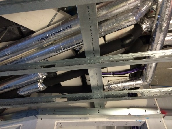
LTHW and CHW flow and return pipework above the ceiling grid of an apartment. The pipework had not been installed as per the drawings which means the lagging is now clashing with the flat duct work.
SRW’s solution to get around the clash between CHW pipework and the flat duct work is to use armaflex (black lagging above) instead of the normal Kingspan (silver), which isn’t acceptable. Why not? The employer’s requirements detail a specification for lagging on pipework which details the thermal conductivity of the material and thickness of insulation dependant on size of pipework. In this case the armaflex fails on both thermal conductivity and thickness. Although a 1 m length of sub standard lagging is unlikely to impact on the performance of the heat interface unit the main concern is that we are dealing with CHW pipework. Sub-standard insulation may lead to condensation forming on the lagging which will drip onto the ceiling and eventually result in a stain.
3. Clashes which prevent valves from operating which would prevent filling and flushing from taking place as per the RAMS.
My involvement in this element of the project has reinforced conclusions that I have previously drawn: the importance of getting out on site and looking at the progress of an installation on a regular basis, not just when it is offered up at an ITP hold point can not be under estimated. In addition far more information can be gleaned by talking to the bloke doing the installation than the manager of a main sub-contractor.
Non Commissioned Officer Academy Ft Drum
The NCOA will be a mixed use building to house routine NCO promotion training, similar to the Royal Engineer Section Commanders’ Course. The building will house the instructional classrooms, administrative offices, some accommodation, an auditorium, changing facilities and personal weapons storage. It will also house a 15 ft high training area (Room 140 on Figure 1) to be used for drill practice and physical training when weather precludes it from being conducted outside.

Figure 1: Ground Floor Plan.
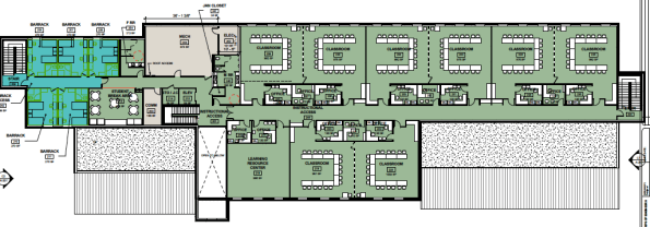
Figure 2: First Floor Plan
The project proposal form had to demonstrate the need for the building, which was that it will replace twenty World War II temporary structures. This will result in a better training environment and reduced utility and maintenance costs. The new building will cover 45,700 sq ft and the project value is currently set at $19 million USD. In order to justify this cost a qualitative economic analysis was executed looking at the alternatives of renovation, maintaining the status quo, leasing and new construction. The status quo was deemed to be unacceptable and other alternatives would have only been a temporary solution.
The project is being contracted as a design, bid, build and the design timetable is organised such that the build contract is due to be awarded on 30 September 2016. This is the last day of the current financial year for USACE and so allows funds to be attributed from this financial year. This presents a risk because if the contract is not awarded on this date then the money attributed to this year will need to be spent on another project or will be lost to the Garrison. I am not privy to information on other mitigating circumstances at programme level, however if some float time had been built into the design schedule this would mitigate the issue at project level. The current design schedule has the following significant deadlines:
35% Design Stop – 18 December 2015.
35% Design Review Conference – 20 January 2016.
65% Design Stop – 28 March 2016.
90% Design Stop – 2 June 2016.
95% Design Review Conference – 28 June 2016.
The date of the planned 90% Design Stop means that I should be able, negating the chance of delays, to see the design work through to this stage.
Given the date of the 90% Design Review Conference it is unlikely that I will be able to see the design through to this point, although the most important experience will have been gained by this point on the design front. The contractual affairs will be dealt with by USACE NY District so there will be no loss of experience by leaving at the 90% design stage.
The design team structure being used by USACE for this design is spread across two USACE Districts and a Design Consultant located in three separate States. The project and the Project Manager is stationed at Fort Drum, NY and is part of NY District. Therefore the design contract naturally falls to NY District’s Engineering Division. Therefore the Design Manager, Architect, Plumbing and Electrical elements are from NY District’s Engineering Branch. Because NY District had insufficient staff to conduct the design of the structural, civil, mechanical and fire protection elements requests were sent to the other Districts within North Atlantic Division. From these Baltimore District was able to staff the Mechanical and Fire Protection elements. As no districts within the Division could support the civil and structural elements these were subcontracted to Pond Consulting, a design consultancy based in Ft Worth, Texas.
Because of the extended lines of communication liaison has already been difficult. A notable occurrence was the design model having to be rotated as it was created 180 degrees out of orientation. As each of the designers across three sites had different linked models this took a week of emails and phone calls to rectify. The issue would have been mitigated against if a central BIM manager was employed on the project, however neither Baltimore nor NY District currently have the post filled.
The new building is to be built on Fort Drum which is in the North of NY State for which the design temperature ranges from a winter design temperature of -30°F to a summer design temperature of 90°F. Significant measures, such as the inclusion of glycol in the hot water system, will have to be taken to ensure the winter design temperature can be met without causing equipment damage.
My part in the design will be to assist the mechanical engineer, Tim Wheeler, in the design of the HVAC system for the entire building. Work for the 35% design is a simple design analysis, setting out of the mechanical rooms, as shown in Figure 3, and specifying the HVAC system type. At the 35% design the room layouts, and therefore volumes, should be fixed to allow the detailed design to take place.

Figure 3: Mechanical Room at 35% design, the eagle eyed will notice that it does not line up with the ever changing floor plan. hence waiting until the 35% design stop to continue.
To 35%, as they are discrete elements I have been given a radiant floor design and a Building Lifecycle Cost Analysis (BLCCA) to complete. The radiant floor will be in the training area (Room 140), which is to be used when it is too cold to train outside. The BLCCA is to assess the viability, or otherwise, of using a Ground Coupled Heat Pump (GCHP) system in place of the air-cooled chiller and 70% of the heating load, the remaining 30% being supplied by a Natural Gas powered boiler.
And that’s the situation as it stands at the moment.
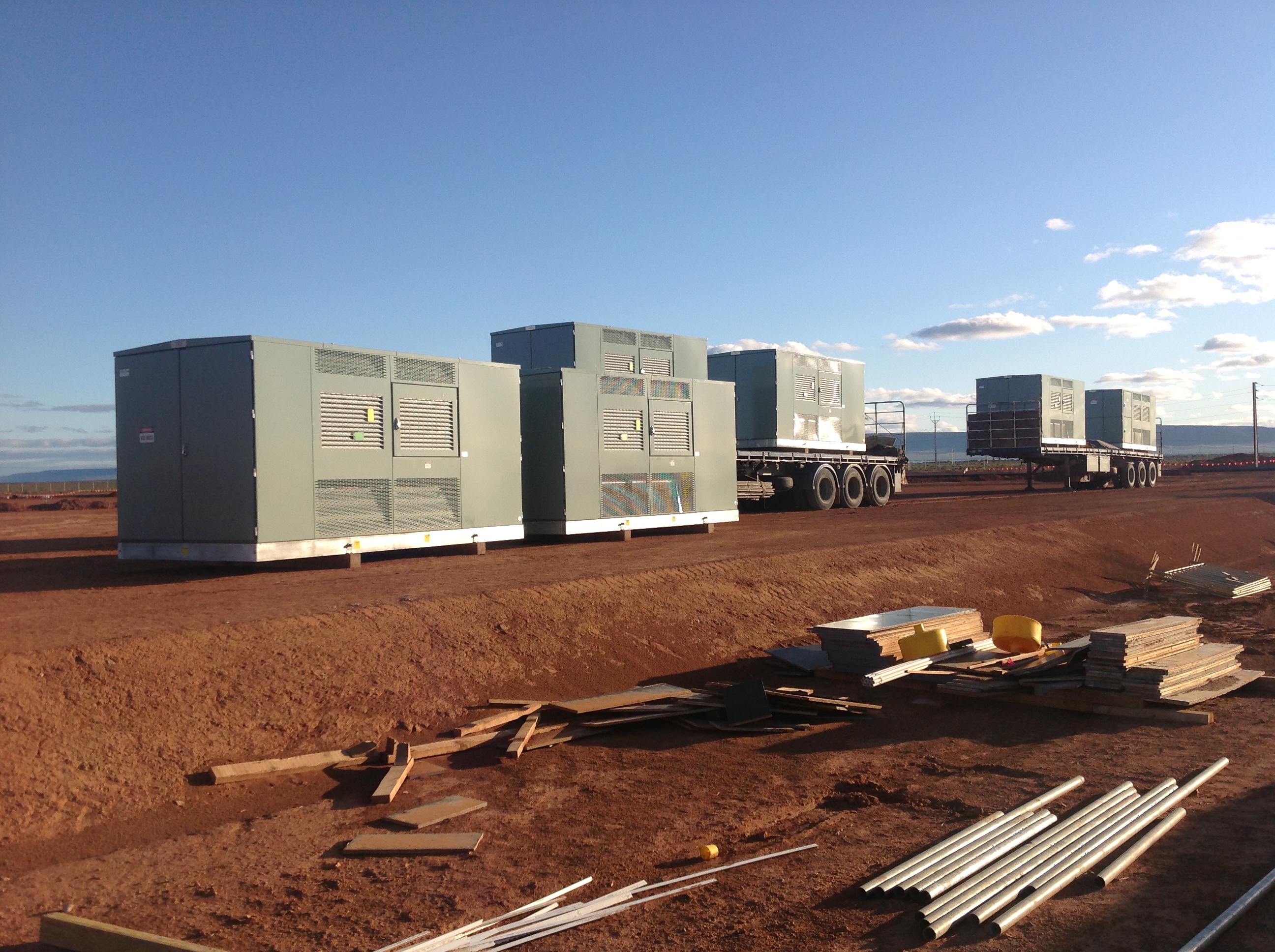
Sundrop Farms Update
The head contract at Sundrop Farms splits the project into five (5) Separable Portions (SP’s). The table below is taken directly from the contract, with no further description offered in the document.
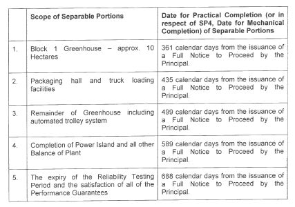
Not long after construction began on site it has become apparent that there was a discrepancy between what John Holland (JH) and the client, Sundrop Farms, believed this date actually meant. JH have always gone down the line that this is the date from which Sundrop Farm will have access to two of the greenhouses (10 hectares total). After which the client will begin their fit out of the greenhouses, which includes approximately eleven weeks of activity per greenhouse. Sundrop Farms believe that this date represented the date in which the two greenhouses would become operational, i.e. they could begin planting.
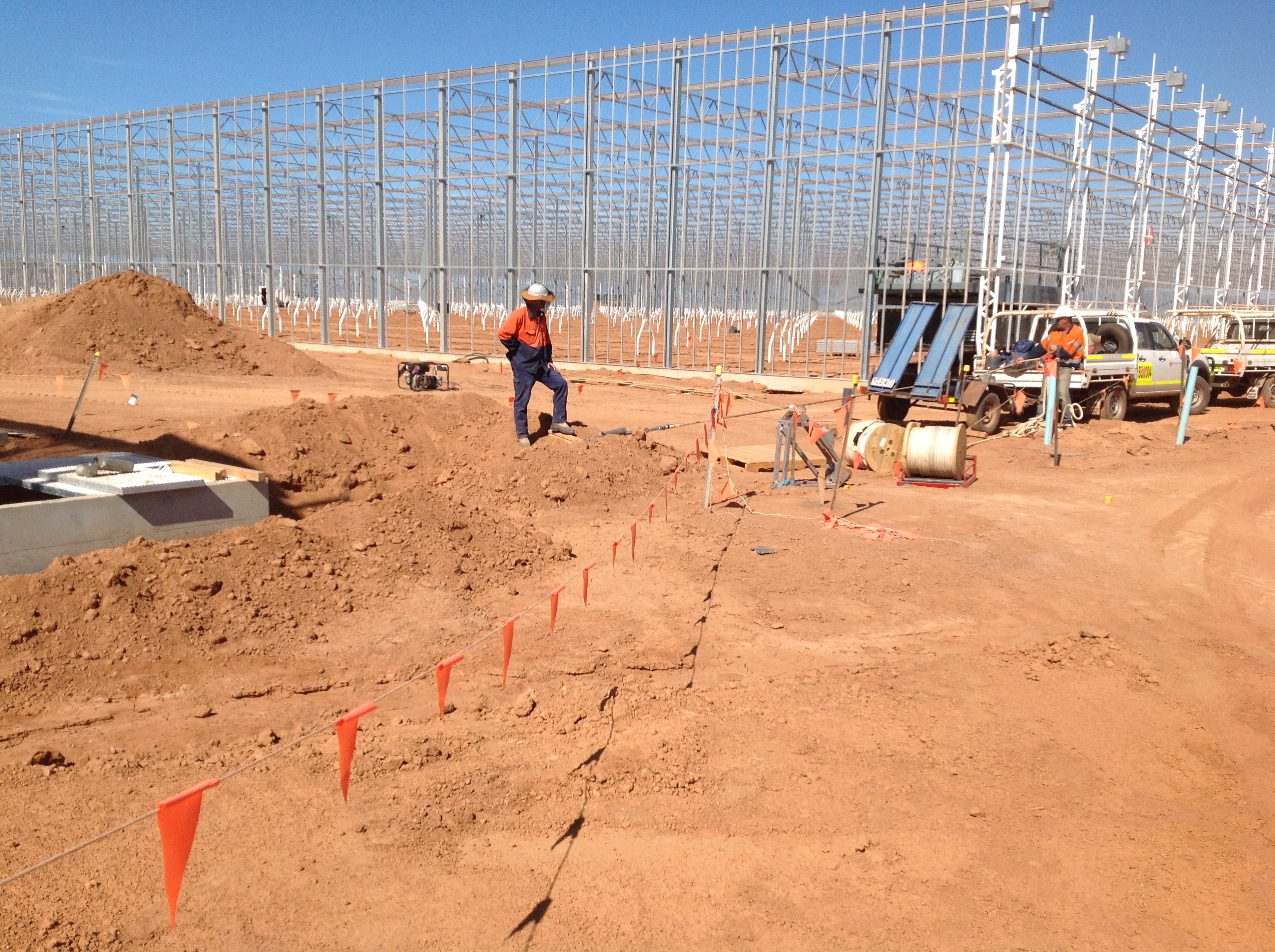
Site Progress
Eventually it was agreed that the JH proposal would be used. There was no further information stated in the contract for the client to point to and as the balance of plant is included under SP 4, the greenhouses could not be operational as it would have no heating (although this is not currently required). However JH have allowed Sundrop Farms access to the greenhouses early to begin the fit out in a beneficial occupancy agreement and a variation order has been issued to provide heating early (I plan on doing a TMR on how this is going to be achieved).
As JH and the client look towards completion, preparation activity for the operation of the plant is now beginning to build up. There are now commissioning managers both for JH and the client on site and a commissioning plan is taking shape. In addition the client has engaged a public relations company to publicise the project. As a result there have been a number of press visits to site, including the BBC. The competition is not hanging around either, Sundrop Farms has a ten year contract with one of Australia’s largest supermarket chains. Another large Australian supermarket this month launched a new brand of tomatoes called Sundrops, not everyone is convinced this is a coincidence.

Sundrop Tomatoes
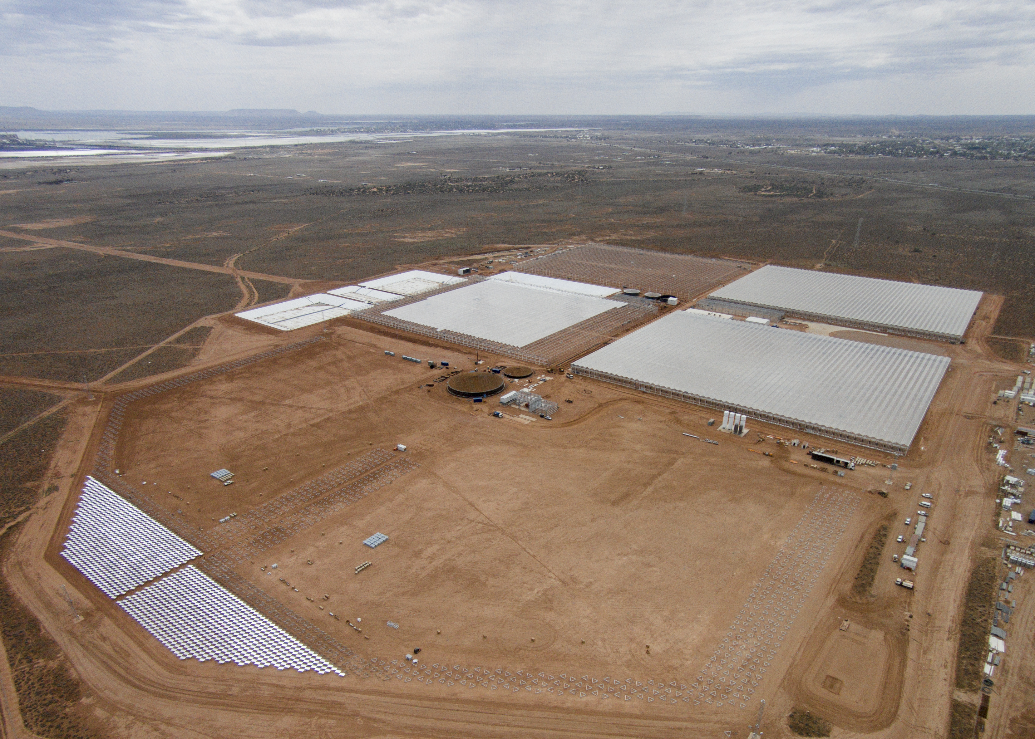
Site wise progress continues at a quick pace. I have been running with the installation of three pump stations, the lining of the lagoons, pipe racks and now the installation of the solar tower, as well as coordinating the delivery of the mechanical equipment on site. JH have come to the conclusion that the two civil engineers on site won’t be able to absorb my work load and have had to recruit a mechanical engineer, so I guess I must have been doing something right.
With the summer months now upon us complaints from the subcontractors have switched from water logged roads to snakes, dust and heat. The temperature has steadily been rising, especially so inside the greenhouses. As a result the client and the subcontractor constructing the greenhouses agreed on a solution. They organised and paid for the roofs to be painted with a temporary chalk based paint, by helicopter. Not an easy task and I’m not sure how JH escaped picking up any of the cost. It would have been interesting to capture some before and after data to see how effective this is, but unfortunately no one took any before readings! Although last week Port Augusta was the hottest place in Australia, with temperatures exceeding 45 deg. Inside the greenhouses where workers are currently installing netting and grow wires in the eaves, the temperature apparently hit 58 deg, this was with the paint in place.
Helicopter Spraying the Roof
Oz PCH – EMC Gland Wars: The Subcontractor Strikes Back
Introduction
This is a follow-up blog from the previous Electromagnetic Compatibility Concerns. It discusses the on-going issue of RF emissions leakage from VSDs and their associated mains power cable. Please feel free to re-read my previous blog for the background to this issue.
Outgoing Mains from VSD
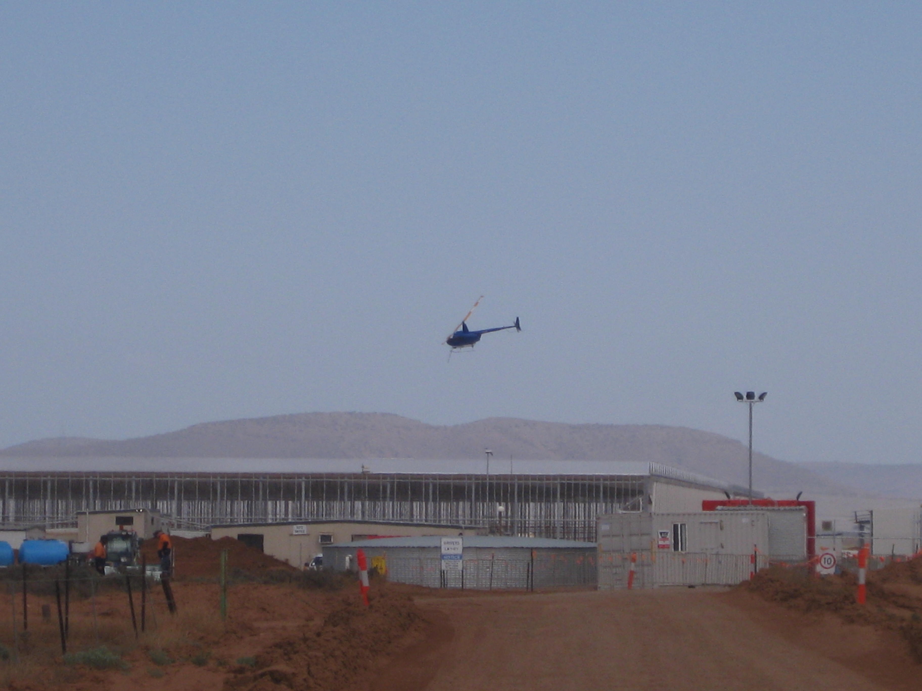
After being issued with a Non-Compliance Report (NCR), Fredon have addressed part of the issue. They have now fitted an EMC gland to one of the many VSDs which we, the commissioning team and NDY (design consultancy) reviewed. Figure 1 shows the new gland (red circle) but there was still an issue, hence the review before reworking all incorrect VSDs.
Figure 1. New EMC Gland Fitted to VSD.
They had left the pig-tail (covered in green heat shrink) and connected it to the earth terminal as seen in Figure 2 (red arrow). Why is this an issue?
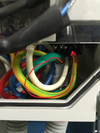
Figure 2. Pig-Tail still Present and Connected to Earth Terminal.
The fact they now have the correct EMC gland in place, which ensures a 360 º connection to the metal base plate and is connected to the rear metal back plate of the VSD (which is connected to earth) makes the pig-tail superfluous. It also potentially acts as a source of RF emission which is what we are trying to reduce. Therefore, it should be cut off when the new gland is fitted; this has now been instructed for all installation of EMC glands to VSDs.
VSD to Motor Via Isolator Switch
A further, and much bigger issue is the power cable that from the VSD to the motor via an isolation switch. Here Electro Master (subcontractor to Fredon), are still saying what they have installed is correct. Figure 3 shows the switch with plastic glands top and bottom.
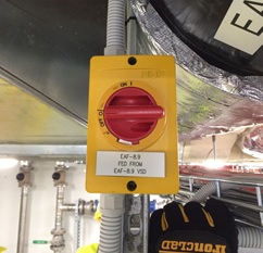
Figure 3. Isolator Switch between VSD and Motor.
When asked why they hadn’t swapped them out for proper metal EMC glands they referred us back to the their original response to the NCR stating that – what they have installed is in fact better than what the specification requested, where by relying on a compression fitting to achieve galvanic connection is a point of failure.
What Electro Master has failed to understand is the principle behind what the cable screening is actually providing. Figures 4 & 5 shows the wiring arrangement within the isolator switch.
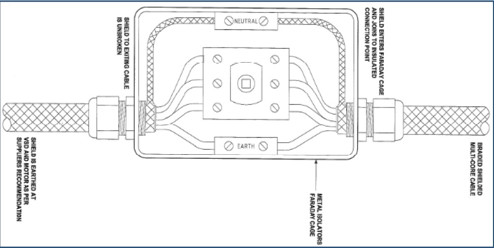
Figure 4 & 5. Electro Master’s Wiring Arrangement as per the Isolator Switch Installation.
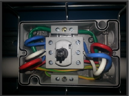
Figure 4 & 5. Electro Master’s Wiring Arrangement as per the Isolator Switch Installation.
The metal switch housing acts like a mini Faraday Cage and Electro Master were adamant that as long as the screening was continuous through the switch, by connection via the neutral terminal, then any RF emissions will be kept inside the Faraday Cage. However, this is not true due to the plastic glands used. Effectively, as soon as the screen is pig-tailed and the 3-phase and earth cables exposed, the RF emissions they produce are free to emit through the air inside the Faraday Cage which will then leak out through the plastic glands.
The solution is to install the screen being in contact with the metal housing via metal EMC glands either side of the switch and with the pig-tail cut out. This then completes the screening and the Faraday Cage will work as per the theory.
This is substantiated by the following two papers found at the links beneath:
Variable Speed Drives and Motors – GAMBICA / REMA Technical Guide.
Best EMC Installation Practice for VSDs – Technical Manager – Power Electronics.
According to the GAMBICA Technical Guide – “Where local to motor isolation is required for safety purposes, it is essential that the switch enclosure should be conductive, and form part of the “Faraday Cage” surrounding the entire PDS. This means that the cable screens should be correctly bonded/glanded to the enclosure”. As shown in figure 6.
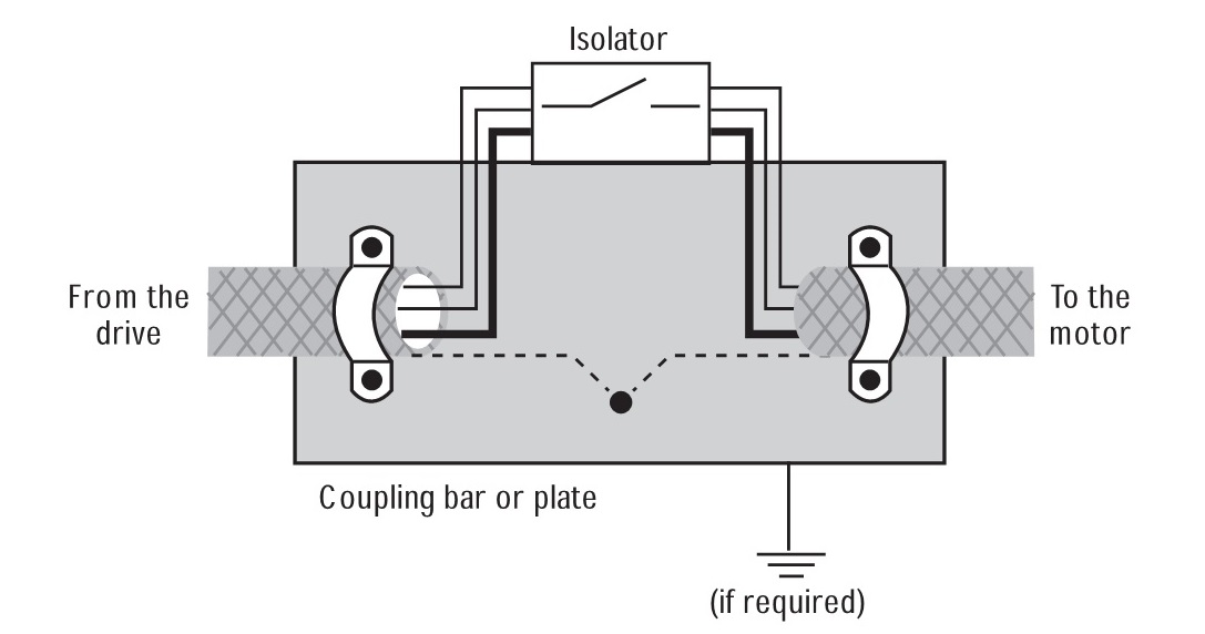
Figure 6. Arrangement for Interruption to Screened Motor Cable.
Additionally, Best EMC Installation Practice for VSDs states that shown in figure 7.
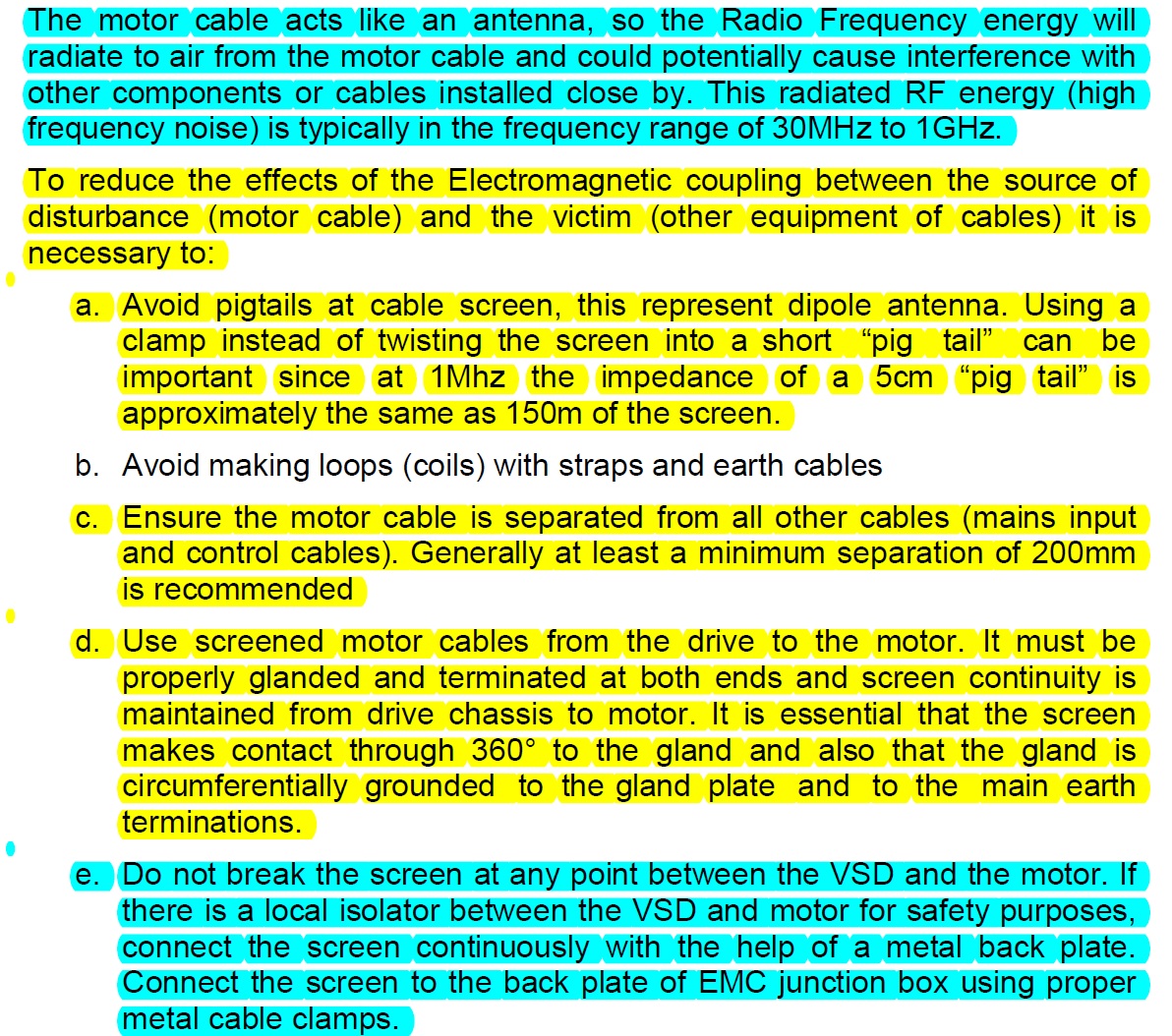
Figure 7. Extract Referring to How to Reduce the Effects if EMC.
Contradiction
However, after further research the following document was found which, to some degree, contradicts the other papers above.
Schneider Technical Note – VSDs: EMC Screen & Output Isolators.
Schneider’s Technical note states that “Common practice is to use an EMC gland to connect the shield into a metal enclosure to continue the Faraday cage, but safety requirements often mean that the enclosure must be bonded to ground at that point as well and hence compromises the EMC HF return path”. As shown in figure 8.
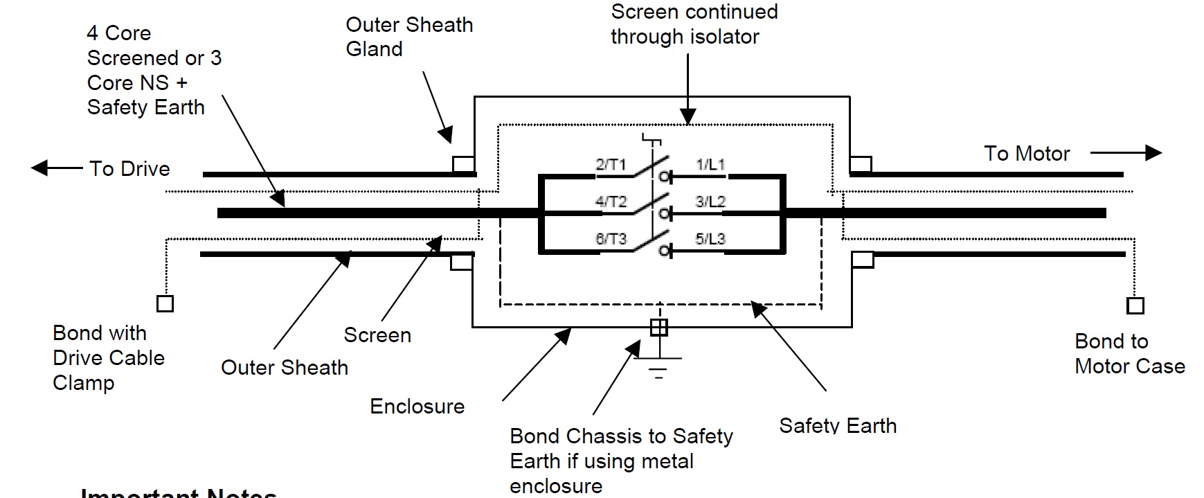
Figure 8. A Practical Work Around for Maintaining Safe Bonding and an Uninterrupted High Frequency EMC Return Path.
Important Notes:
- Continue the screen braid through the isolator ideally using the same braid and keeping this as flat as possible. Avoid pig tailing and/ or twisting the screen.
- The screen is not connected to the chassis or earth at any point other than at the motor and drive.
- Ideally EMC type glands should be used to bond the screen to the motor chassis
- Use the drives EMC shield Clamp to bond as shown.
This is exactly what Electro Master has installed but they have still used pig-tails which is bad practice.
Conclusion
Through reading the papers above, limiting the RF emissions seems imperative in ensuring there is a low impedance path to enable the current to return to its source. My conclusion is that the high frequency low impedance path between the VSD and motor must be maintained (by the screen) even if there are local motor isolators installed in-between. In this particular case because the VSD and motor are both grounded to earth (at each end) then avoiding a third earth connection is imperative otherwise you end up effectively splitting the cable which breaks the single faraday cage theory; the reason why Electro Master are adamant that they should not connect the screen to the metal isolation box which is earthed.
Therefore, it is my opinion that what Electro Master has installed, based on the earthing arrangements used, has met the intent of the specification. The ‘litmus test’ is the implication associated to leaked RF emissions that could cause interference with specialist medical equipment which could then potentially result in a child’s death.
Although patient safety must always be the priority, you could also consider other factors that would be a consequence from making Electro Master strip-out and install EMC glands, such as: increased cost (to Electro Master – up to $40,000) and potential time delays to commissioning.
What is very apparent is this area of electrical engineering is highly specialised and above my experience level as well as anyone else’s in the office. So although I conclude that Electro Master’s installation of the isolation switch being sound, we have and must refer the issue to NDY for them and their specialist electrical engineers to provide us with an answer for the way forward.
Site Diary
When I arrived on Ph2 I was given four options for maintaining a site diary:
- The official BAM form (Not very user friendly and requires printing and binding)
- A home made excel spread sheet (designed for a different job)
- iPad Field 360 (the consensus from our site is that it is a v.poor piece of software that requires a great deal of time and investment)
- A blank note pad!
I have tried all of these and can conclude the classic note pad won for its ease and ability to go anywhere!!!
However…maybe technology has finally turned up trumps.
Our GF has been using an App on his phone called ‘Day One’. Its a daily diary app that allows you to tag photos, write text, etc but auto links a location, time, weather…. Furthermore, it allows you to search for events with far more ease than the other IT options in use with BAM. All events can be shared with ease or exported as pdfs.
I have use it now for a few weeks and it has increased the level of detail I have recorded as well as drastically reducing the time and effort involved to stay up to date. The only negative I can identify is the risk of using mobiles on site which must be managed accordingly, dependant on your site.

Diary overview with thumbnails and titles.

Annotated photo with auto linked information
In my opinion it’s a tick VG for Day One and certainly something for the Ph1s to consider if they are not constrained to company policy.
Pre-Commissioning Flushing
This blog will focus on preparing for pre-commissioning flushing of one of the LTHW and CHW systems at Battersea. As a means of introduction and for those that aren’t sure, flushing is the cleaning of pipework to ensure that it is free from debris, settled solids, suspended solids and certain bacteria. This is to ensure that sensitive equipment isn’t damaged (plate heat exchangers and terminal units) when incorporated into the system, that commissioning valves can operate correctly and that microbiologically induced corrosion doesn’t occur.
The contractors involved are:
Skanska Rasleigh Weatherfoil (SRW)- Main MEP contractor
Price Building Services (PBS) – Pipework trade contractor
PH Water & Air Technologies (PH) – Flushing trade contractor
Wyse Power (WP) – Temporary services
When looking at flushing a system there are four basic elements that need to be in place (I’ve annotated who is responsible for each element):
1. A water supply – Down to Carillion to supply
2. Electrical supply (for pumps to get up to required flushing velocities) – Carillion to supply
3. Drainage – Carillion and SRW to supply
4. A complete system – SRW to supply via PBS
I have been managing the preparation for flushing from Carillion’s point of view. This has meant ensuring that points 1 to 3 are in place to meet SRW’s requirements and also ensuring that the approach SRW will take complies with the employer’s requirements which essentially means complying with BSRIA’s BG 29/2012. In reality my main focus hasn’t been on the technical detail and has been on the simple task of trying to prevent SRW from flooding 6 floors of semi-fitted out apartments. The following is worth noting:
Water supply – The permanent Boosted Cold Water Supply (BCWS) on site was not yet installed, therefore a temporary supply was required. This was fairly simple to sort out. I gained confirmation from PH on what their requirements were (a 50mm supply) and then arranged for WP to install a spur from our site temporary supply (50mm) into the plant room where flushing would be taking place with a double check valve fitted to the end for PH to connect onto. If I’ m honest this was a bit of a gamble on my part. As I’ve come to learn this is just a game. Points 1 to 3 above were down to me to sort out. The target start date for flushing the system was 17 Aug 15 therefore in order to avoid a relevant event occurring (JCT term for something which causes delay) and delay notice being issued by SRW I has to ensure we had a water supply. The reason why this was a gamble is that although I was tapping into a 50mm site supply, this supply comes from 2no 5000l break tanks which back in Aug were supplied by a 25mm pipe. PH had a discharge license for 10000l a day and therefore there was a risk that PH’s activities could disrupt the water supply to site. Why did I take this gamble? I knew SRW would not have their system complete in August and I knew a larger water supply was coming to site in the near future. By putting my supply in I protected Carillion contractually – it’s much harder to prove a supply isn’t up to the job than it is to highlight that there isn’t a supply in place at all. What is more frustrating is that I needn’t have taken this gamble at all. I have subsequently read BSRIA’s BG 29/2012, which gives clear guidance on the size of supply required in Table 3.
An extract from Table 3 of BSRIA’s BG 29/2012:
less than 2000l system = 25 mm supply
2000 to 10000l system = 40mm supply
greater than 100000l system = 50mm supply
PH were simply asking for the largest supply they could possibly need, without looking in detail at the size of the system, in order to cover their bases. Assuming that our riser pipework remains at it’s largest diameter and the horizontal distribution pipework is the same as the largest size then the volume of the system comes out at 1959l – I only needed to provide a 25mm pipe which would have been met by our 25mm site supply leaving 10000l a day for site use (more than enough). An easy lesson learnt.
That’s just over 700 words, so I’ll leave it there for this blog and provide comment on my part in confirming SRW have completed the system (visual inspections, air test witnessing and NCRs) at a later date.
As an aside I’ve only got two weeks left on site. If anyone on phase 1 knows that they are coming to Battersea Power Station Phase 1 let me know and there may be scope to arrange a visit to site before I depart and switch focus to phase 3.
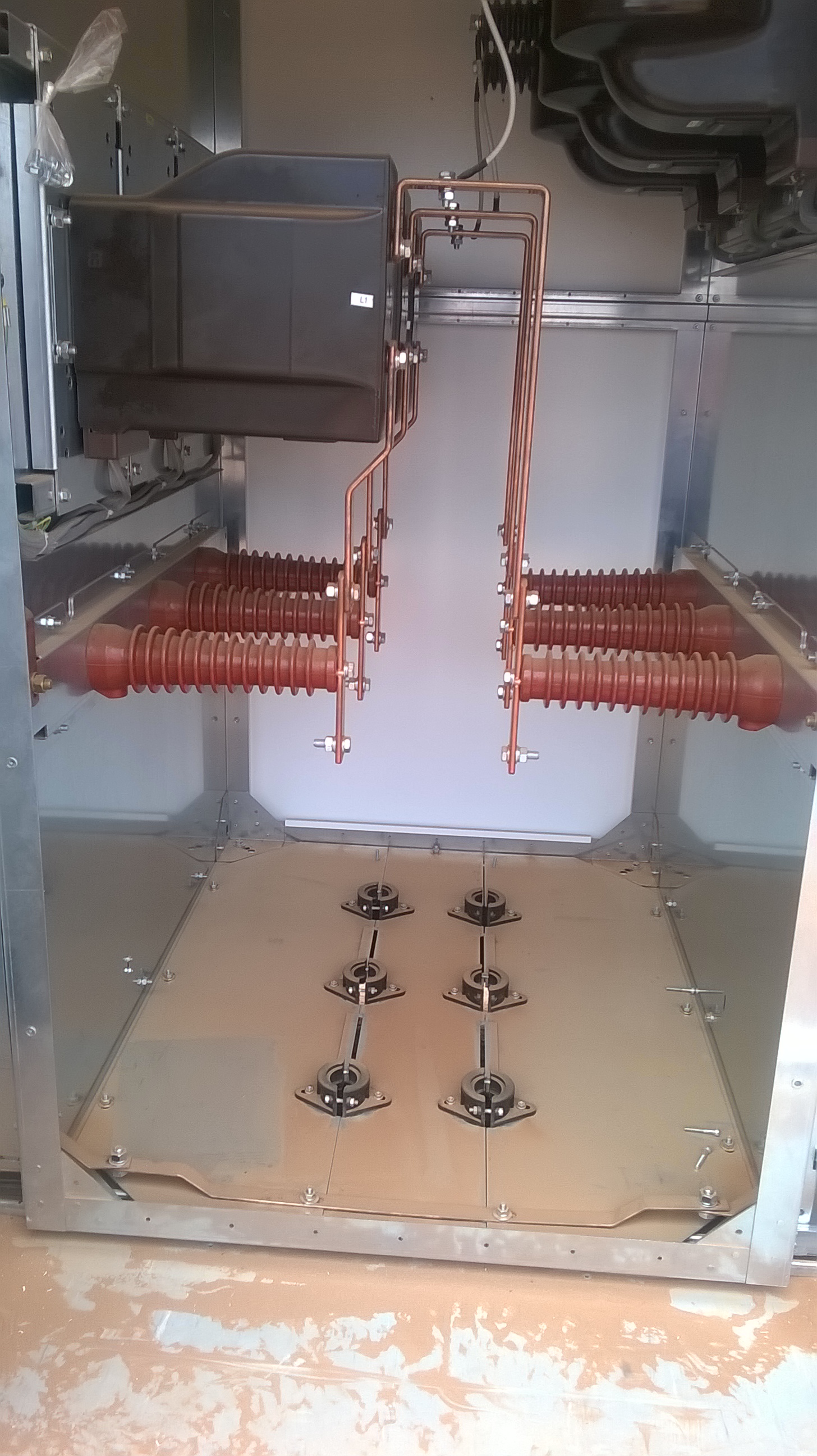
Sundrop Farms HV Design and Installation
The installation of the high voltage (HV) system for the Sundrop Site began earlier this month. This blog aims to give an insight into the design and some of the issues that have arisen so far with the installation. The electrical design for the Sundrop Farm project was initially done by KBR, then handed over to CNF & Associates. The onsite installation of all electrical items on site is subcontracted to Broadspectrum. On site John Holland (JH) have got an electrical supervisor come engineer who monitors the subcontractor.
Design
The HV design is based on a ring main with the 33kV coming in via overhead lines to the main switch board kiosk, which then feeds six transformers that are positioned around the site via a network of underground cables. Each of the four greenhouses has its own transformer, as well as the balance of plant area and a separate one for the generator/turbine. In addition to the mains supply the site also has a 1.5MWe steam generator and equivalent sized standby diesel generator. These generators supply 415V to a 33kV step up transformer to reticulate the generator output back into the site HV system. The steam generator can only operate in parallel to the mains power, operating as a base load generator and will not operate when the standby generator is in operation. The diesel generator can only operate when the mains supply is disconnected and will only supply the critical loads to site, 1.5MVA. Critical loads on site are based on ensuring the crop is not damaged on site. These comprise of 100% operational irrigation system, 50% operational cooling system and 100% operational heating system.

Sundrop Farm HV Design – If anybody wants a clearer copy of the image please ask.
Harmonics
The majority of the loads on site come from rotating machinery, primarily from 1152 motors that are used to circulate air around the greenhouses. Because these loads are non-linear they have the potential to generate significant harmonics. For the civil’s out there harmonics are bad they have the potential to increase the current in the system, causing increased heating in equipment and conductors, shortening machines life and increasing running costs. In addition limits are generally set by Utilities Company on the amount Total Harmonic Distortion (THD) a consumer can have, in this instance it is 1.67% allowable. The estimated value for Sundrop Farms exceeded the value set by the utility company, South Australia Power Networks (SAPN).
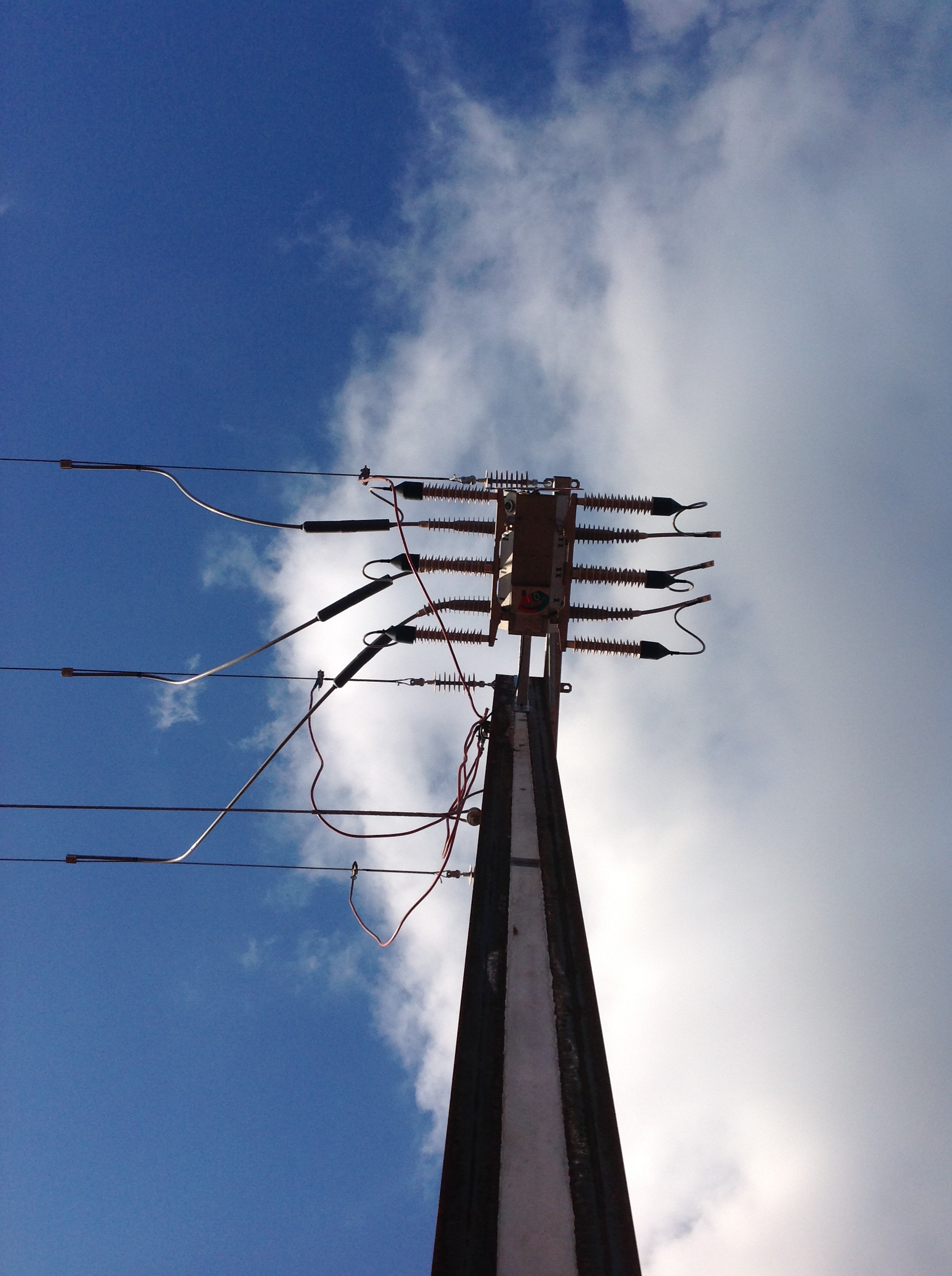
Pole Mounted Switch above the 33kV Kiosk
To reduce this value the designers had a number of options, rectifiers, harmonic filters or pulse width modulators. All of which have significant cost implications, for the site this was estimated to be around $500k. However SAPN failed to meet the date which they were due to supply power to the site by. They failed to get the necessary permission to erect the HV line across a recognized heritage area, thus their installation was delayed. With this leverage and through negotiation with SAPN, JH were able to move the point of common coupling which is where total harmonic distortion is measured to a substation 6km away. The resistance of the circuit was increased by this additional cable length and reduced the effect of the harmonics to a limit that was acceptable to SAPN. The impact on the project of not having power to site – zero as we have yet to get the HV transformers in position.
33kV vs 11kV
Another point I picked up on early in the project was that the onsite distribution changed from 11kV to 33kV on the designs. Through a value engineering process it was identified that significant savings could be realized by removing the 33kV switchroom and the 33kV to 11kv transformer and reticulate power around the site at 33kV, this design change saved approximately $800k. Other savings realized by this change included being able to use smaller cables which equates to quicker installation time and cheaper purchase costs.
Schneider Transformers arrive on site – the unloading of these became an issue when it was identified that they weighed 12t, not the 9t on the drawings!
Installation
The design called for the cables to be direct laid. However when the installation contractor began to develop their program it quickly became apparent that this wouldn’t work on site. The way the cable was routed and the fact that the cable was coming off the same drum meant that the trench would have been open for up to three weeks. This would have resulted in severe access issues across the site and opened JH up to multiple claims from other subcontractors. The solution was to install conduit in the majority of the areas across the site and then pull the cable. The actual cost of switching was between the two was seen as cost neutral. Laying conduit involves more work but it means that the plant used for the installation can be off site much quicker. In addition JH were able to supply the majority of the conduit free of charge, as we had surplus on site from a previous project.
The cable pulls themselves required some detail planning, the longest was 370m long. The cable was pulled using a trailer mounted winch which was in turn connected to a Ute. Even with the weight of the Ute, lubrication in the conduit and rollers the friction encountered during the pulls was such that a second Ute had to be attached to the first to stop it moving.
A poor image of one of the cable pulls taking place.
Other issues encountered so far on site have arisen from the transformers and kiosks supplied by Schneider. The original HV cable in the design was supposed to be three single core cables, however this was switched to a single three core cable, to reduce costs (this was free issued by JH, again surplus from a previous project). However this change was not communicated to Schneider, and as a result none of the cables now fit in to the transformers gland plates because the larger diameter three core cable has a bigger bend radius. The solution to this problem is still in discussion. The current plan is to terminate the cables prior to the transformers getting lifted into position and install new gland plates on site. Not necessarily a big job, but as with everything electrical to get it done to the correct standard will be costly.
The Gland plates in the current transformers – perfect for three single core cables, not so good for a single three core cable.
One of the positive aspects of the installation is that the subcontractor we are using. Broadspectrum are engaged by JH to do the HV and also by our subcontractors VDH and Aalborg who are responsible for the greenhouses and solar energy system respectively. Although this was not planned it does mean that a lot of the potential issues between the various scopes of work, in terms of gaps and interconnectivity have been elevated. Also as the subcontractors are both form overseas it ensures the work carried out is to Australian Standards.
