RE Wall Upstream Walkway and Piezometer Installation; A simple task…
The Reinforced Earth Wall (7.2 x 6.2 x 500m) that is currently being installed on top of the existing Earth & Rock-fill Dam also requires a small walkway on the upstream face. This is required to allow for the inspection of the settlement points as well for monitoring the RE wall itself (panel verticality/movement and for extracting the internal galvanised test straps).

DESIGN
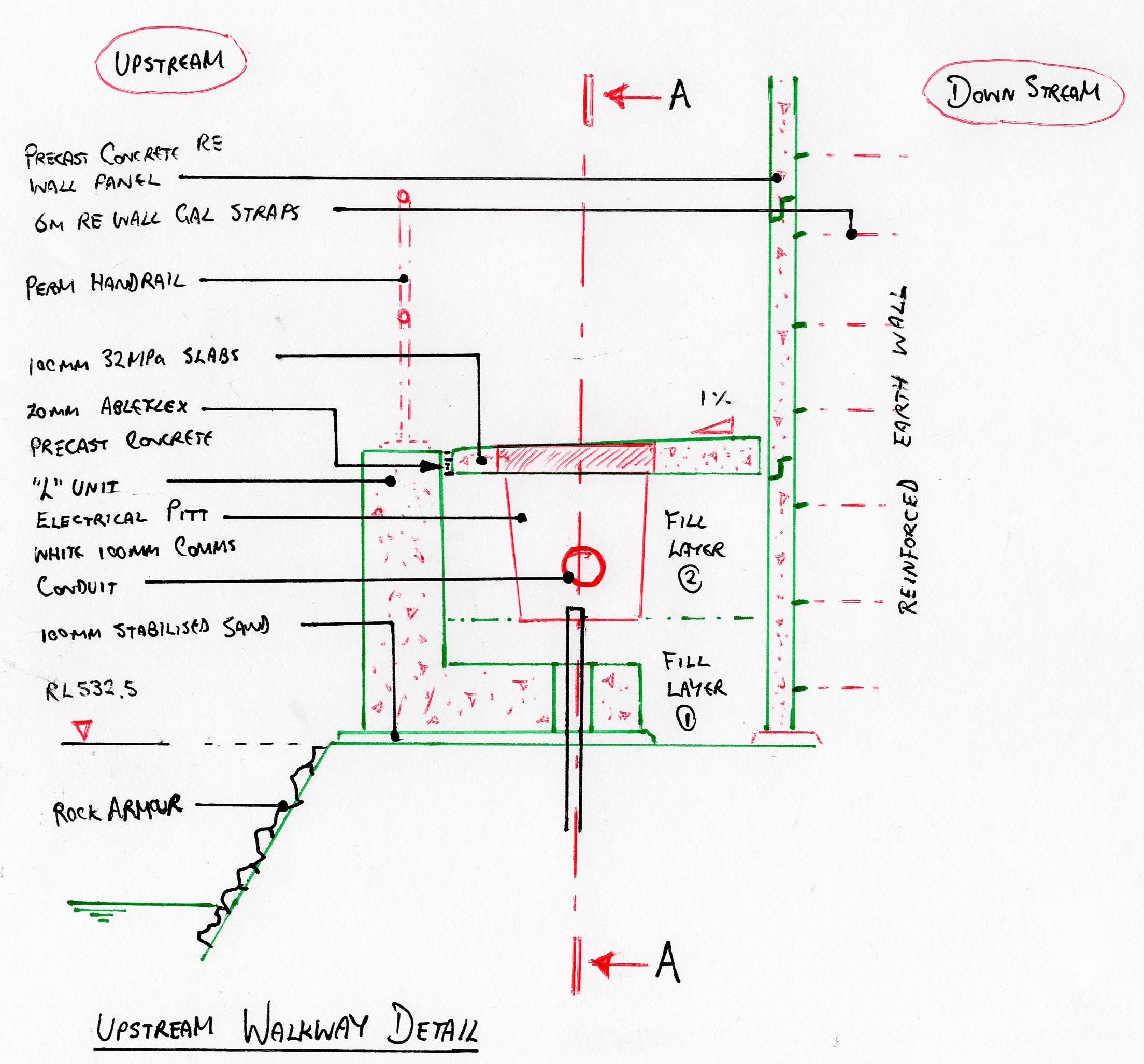
EPSON MFP image

METHOD
- Placement of stabilised sand (100mm). This was simply to provide a firm level surface for the L-Units to be placed upon as the large, angular 4B material produced an inconsistent surface level. It also allowed the temporary handrail to be secured in placed.
- Installation of temporary fall prevention system/ handrail.
- Backfill of rock armour on upstream face. Required to cover the stab-sand and improve aesthetics (..and durability)
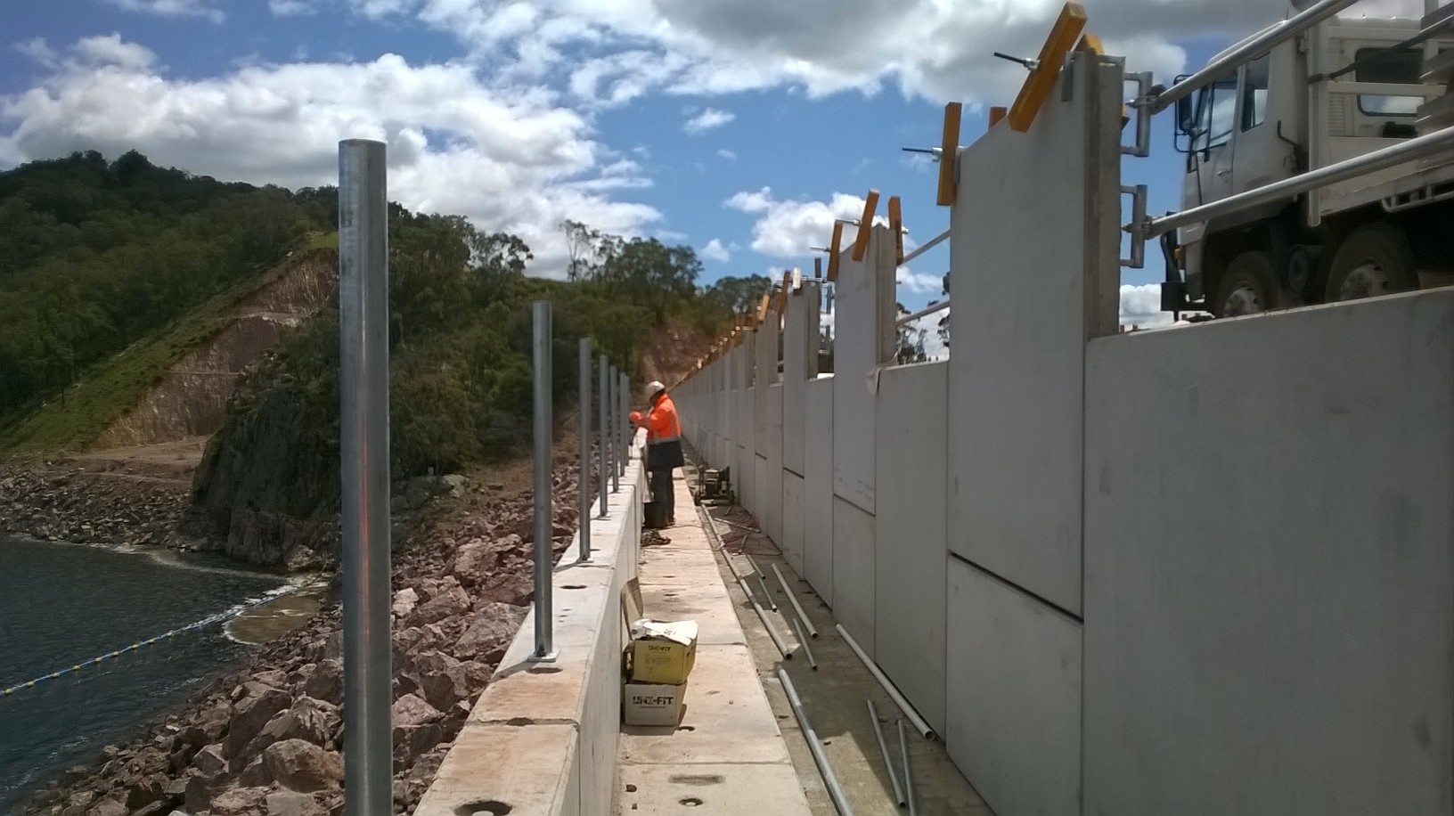
- Installation of precast L-Units. (see photo 1). Originally, designed to be gabion baskets, these precast units were favoured for aesthetic reasons. The finish and uniformity of the units was flagged as being very low.
- Removal of temporary fall prevention system. (Design of fall restraint anchor required- see below)
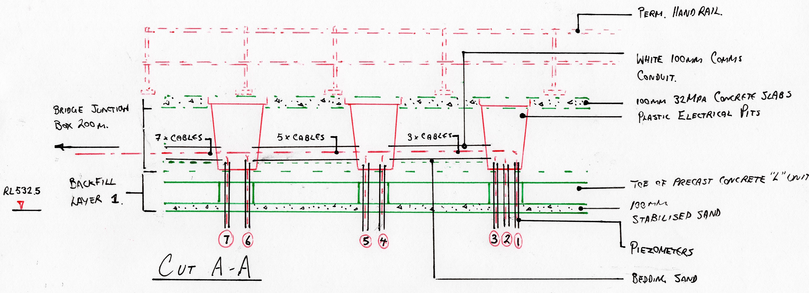
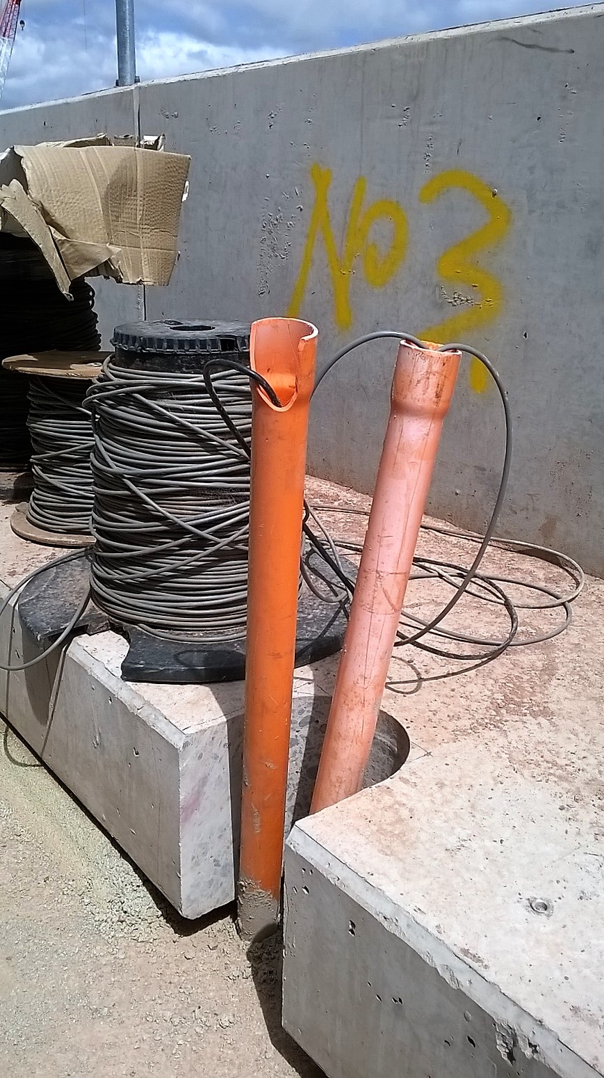
- Core drilling of L-Units to allow piezometer conduit to pass.
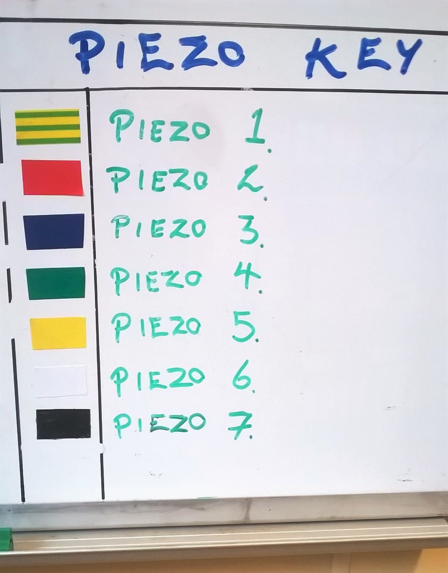
- Piezometer marking/ protection.
- Installation of permanent handrail to top of L-Units.
- Backfill of precast concrete L-Units using large rock-fill material (Layer 1 (0.45m)). Agreed upon by SPE due to large cobble aggregate to be used (20 – 75mm).
- Installation of plastic electrical pits.
- Further placement and compaction of backfill material (Layer 2 (0.45m)).
- Installation of pavement formwork, steel reinforcement, jointing, end stops.
- Construction of concrete pavement (310 x 1.6 x 0.1m).
Point Loading the RE Wall. I assessed that the pumping of concrete from an unfinished RE Wall to a walkway 3m below was the greatest risk to this phase of construction. A 36m pump would be positioned onto the RE Wall crest in order to pump 12 x 6m slabs/ day. Each outrigger leg was rated up to 192 kN but with the walkway so close, it was assessed that this force was unlikely to be approached. Upon receiving the concrete pump technical data, it at first appeared as though we would not have sufficient space (See image below). Fortunately, this was not the case and it was able to safely operate simply using an alternative outrigger configuration. The important dimension was that of the 1.5m exclusion zone from the internal face of the RE Wall within which the outrigger could not encroach. This was likely due to the lack of frictional resistance offered by the steel strapping at such proximity to the RE Wall Face which prevents the vertical panels from pushing out.
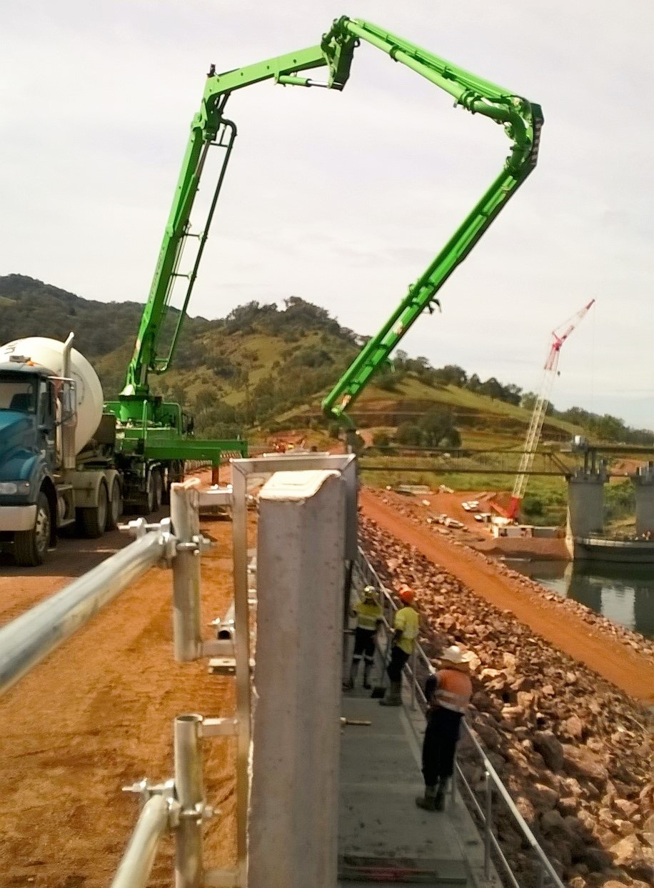
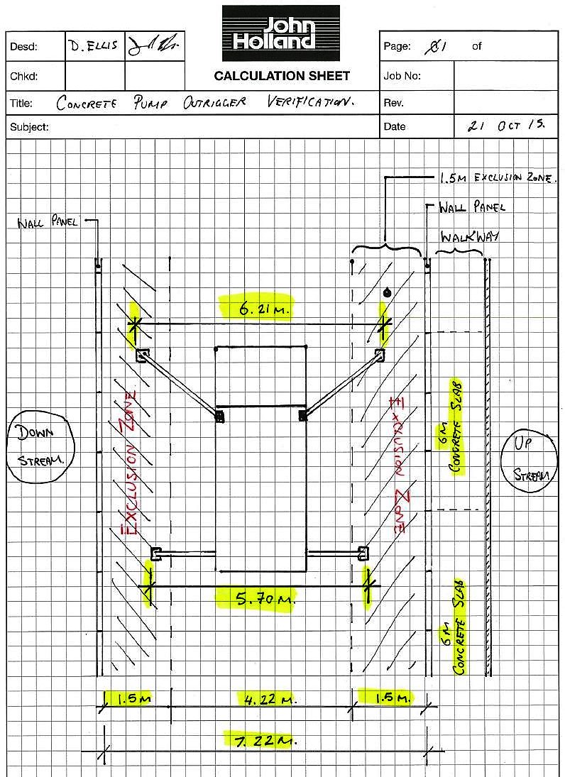
Outrigger dimensions breach RE Wall exclusion zone
Working at Height. Due to the steep upstream face, a temporary handrail was installed to provide a fall prevention system. Once the L-Units were in place the temporary handrail was to be removed. However, workers were required to wear harnesses for the removal of the handrail as it required them to step on the outside of the L-Units.

Due to the lack of fixing points, I was required to design a fall restraint system. M16 5.8 bolt was used with a small steel plate to provide an anchor point for harnesses. The simple anchor design required external verification before it could be signed off. A couple of hours later and the design was approved for immediate use.
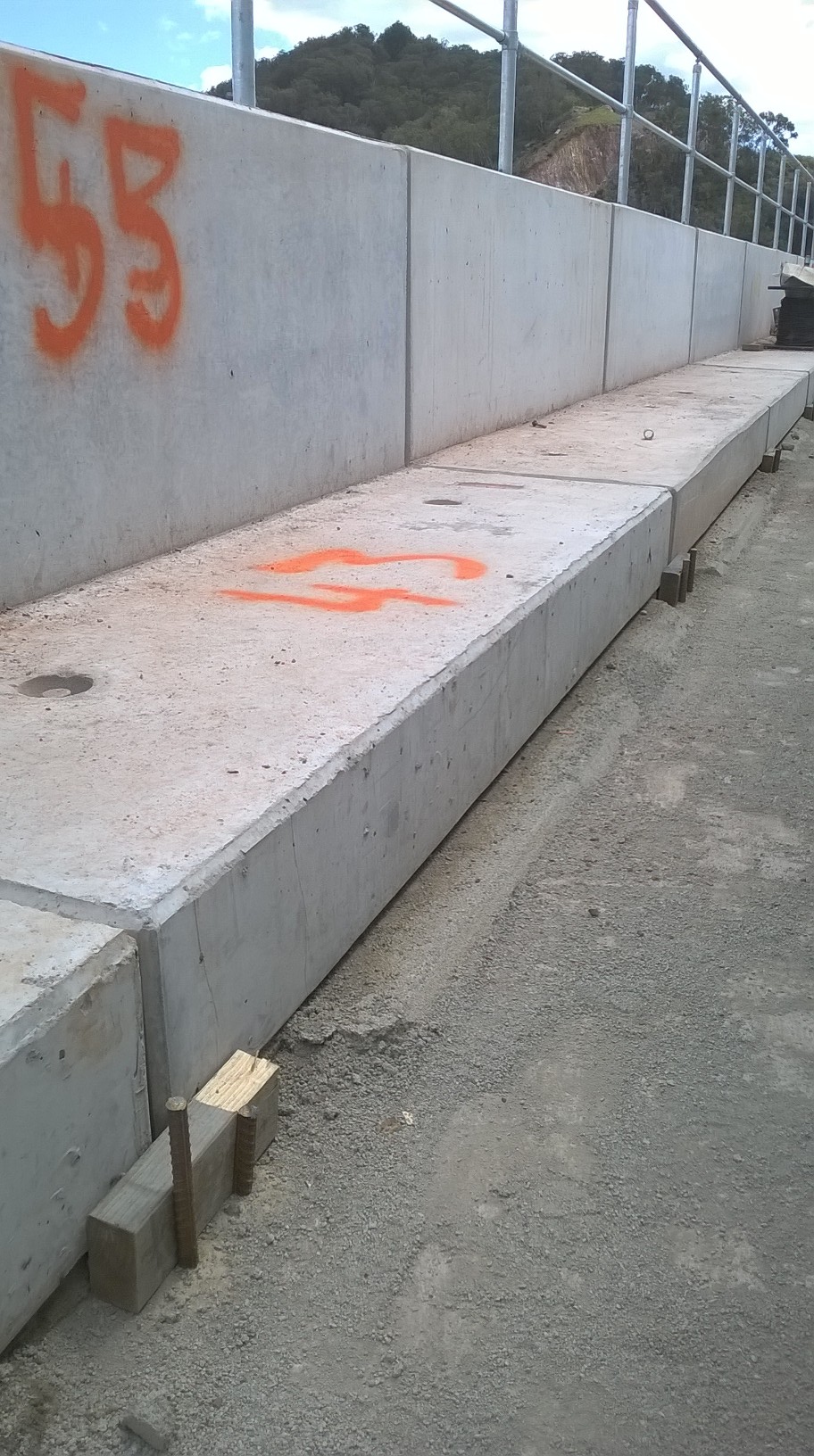
Securing the L-Units. As part of the RECO L-Unit system, hot dip gal sheer keys are provided which meaure 1m in length. These slot vertically in between each concrete unit and ensure that the individual units operate as a continuous structure, whilst allowing a certain degree of movement. However, due to the subsequent placement and compaction of the cobble fill material between the RE Wall and the L-Units, I decided to pin them in place using 4 x steel rods as shown below. This was to prevent the units moving laterally away from the RE Wall as compaction occurred.

ISSUES
Piezometer Alignment. When initially setting out for the installation of the walkway, it soon became apparent that the piezometer alignment would conflict with the position of the precast concrete L-Units. Consequently, 100mm holes had to be drilled through the precast units to allow the piezometer conduit to pass through. As JH were also responsible for the location at which the piezometers rose vertically during prior groundworks (and before my arrival!) it was a simple matter that could have been avoided.
Missing Materials. Despite being fully assured by my predecessor that all components were correct and present I was a little under the moon to find out that approx. 10m of handrail fixings were not accounted for but an additional 30 vertical post were present… A swift call to the manufacturer and all was well.
LESSONS LEARNT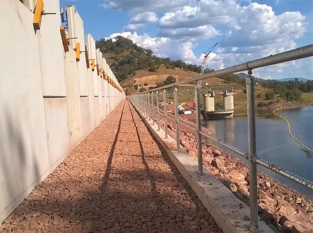
5 x P’s!! – Poor planning lead to several avoidable issues during construction. ie. Precast L-Units requiring core drilling (5 x 100mm Ø holes) to allow for the Piezometers to pass up vertically to the surface of the walkway.
Precast Unit QA – Do not rely on consistent geometry of precast unit in planning.
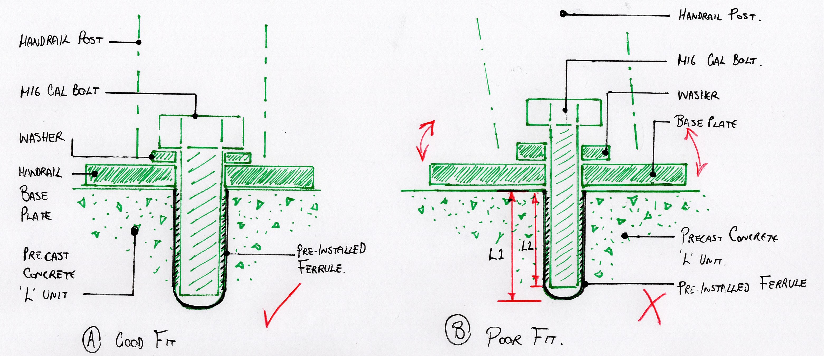
Each of the precast L-Units has 2 x preinstalled ferrules. These provided a metric thread fixing point in precast concrete panels to which the permanent handrail will be installed. Due to the lack of conformity in the geometry of the precast units, the horizontal alignment of all the ferrules once all of the L-units was far from straight (even by Aussy standards). The final handrail would have looked terrible. As such the decision was made to drill and install new ferrules in order to achieve an aesthetically pleasing handrail alignment. See final alignment above.
Check and Double Check material quantities!!
Reo Bar Chairs – Ordered 1000 x 45mm plastic bar chairs to sit on the uneven 4B material. Thought to be too many but required more 75% way through bay construction. Underestimated spacing required due to uneven 4B material…
Bolts and Ferrules. To determine the bolt length that was required for a pre-installed ferrule which is not detailed on the drawings, do not simply measure the ferrule depth using a steel rod (who would do that?..). As the base of the ferrule is rounded, the depth that a bolt can actually penetrate is approx. 5-10mm less than the full ferrule depth. If a bolt then protrudes greater than required the handrail baseplate will be loose (apparently..).
EPSON MFP image
OTHER NEWS..
New Chaffey Dam Site Office resident fancies a brew!

Dan , it would be good to know what the piezometers are monitoring. I would guiess the pore pressures in the up stream face of the reiforced earth fill?
I am also guessing that the mutli piexos coming to the three location are not all reading differeing locations but are redundancy that is normally built into a geo technical monitoring scheme?
Thanks for the update. I’d not worry about additional sealant at the salb/wall junction – sealant will give up long before the wall but the gap will be filled with miscellanous dust and debris anyway. The greater challenge is tha the slab has only a 1% fall which with any irregularity on construction, settlement in the fill or movement of the wall, will soon create a ponding and thefore icing hazard (I know its sunny now but you do get ice there in winter don’t you?). I also notice that the photo of the handrail base shows the solution I would have execed to fixing i.e. depth of ferule is irrelvant if you use thresaaded rod and a top nut. I guess the piezzos are set at different depths in the upstream face?