Archive
CRAC & Pipe
I recently handed back my Leadership in Energy and Environmental Design (LEED) responsibilities, which I’ve been covering for the last several months whilst the actual LEED Accredited Person (LEED AP) was on maternity leave. The timing coincided with the resolution of an issue which was high on the principal contractor’s ‘concerns’ list. It involved a Computer Room A/C (CRAC) unit and is another example of some poor contractual documentation which has led to confusion on this job. The issue has been exacerbated by the fact that the project is constrained quite heavily on what LEED points it can pursue, making those which it can particularly valuable. The issue started with an RFI submitted through the usual channels. It was labeled as ‘hot’ because it was holding up the delivery to site of the CRAC units.
As you can see from the contractor’s calculations below the Life Cycle Global Warming Potential (LCGWP) appears to be in excess of the LEED stipulated value of 100.
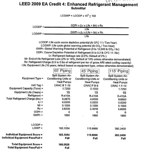
Contractors Evaluation of LCGWP
After a little digging I found out that this calculation was incorrect because it was based on the three units in confinement, when the actual calculation is meant to take the whole system into account. Although these parts of the system appear to be way out of the environmental requirements the system as a whole still passes. This fact made up a part of my eventual RFI response.
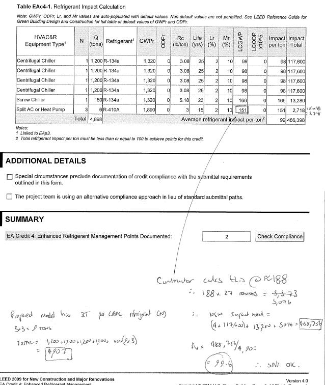
My calculation of LCGWP of whole system
The second part to this, and most importantly is the root cause of the problem. This was in the way that the requirements were communicated; there is conflicting information on the equipment schedule. As you can see below, the table calls for a DRCU-312 unit, but note 4 calls for the DRC-334 model.
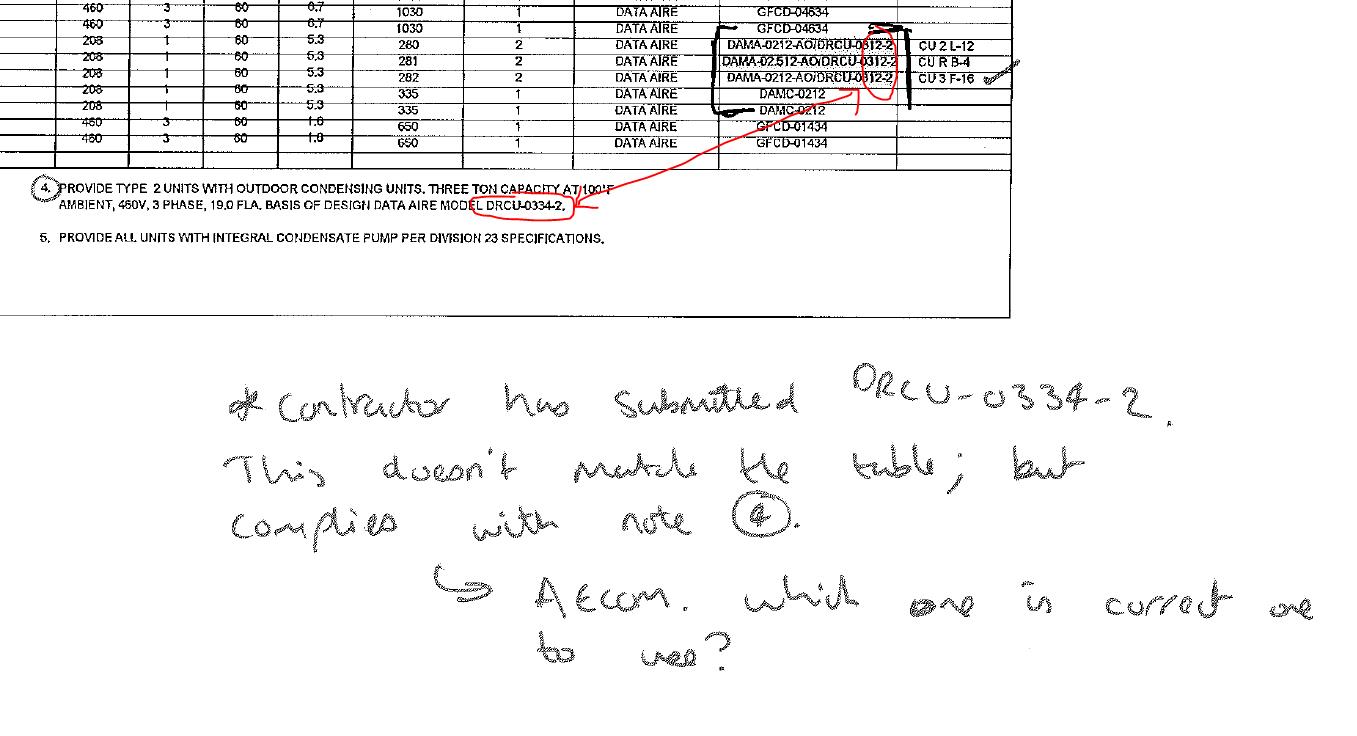
Conflicting information in contract documentation
Although it has been shown that the impact is minimal and the system as a whole still passes the issue has still caused delay in delivering the CRAC units to site. This has in turn delayed the overall system installation. Fortunately this work does not fall on the project program critical path and so impacts are minimized.
This is one example of many which has highlighted issues with the contract documentation. I imagine the designer will have done some design quality control (buildability, inter-discipline co-ordination etc) but they do seem to have missed quite a lot. I expected, on a large project, that there would be some discrepancies and bits of missing information but I have been surprised at how regular an occurrence it is here. Are any of you having similar issues or is it just this designer being slack?
For me, key take aways are with respect to quality control. This is not just a site practice, but starts at the very outset of a project. It is important to control the quality of the contract documentation also, and ensure that the drawings, schedule, specifications etc are all ‘synchronized.’ The impacts of not doing so can affect all three elements of the time/cost/quality triangle. As future PQEs I expect that a large element of this will fall to us to do.
A completely separate issue, but which loosely stems from the same root is a conflict between adjacent projects. Here a drainage run from one project is required to be installed in shared space. The conflict arises due to an electrical ductbank, which is hardened, and has been installed slightly out of alignment, and at a higher elevation than design due to various other site constraints. This means that it now sits pretty much exactly where the adjacent project’s drainage run is supposed to go.
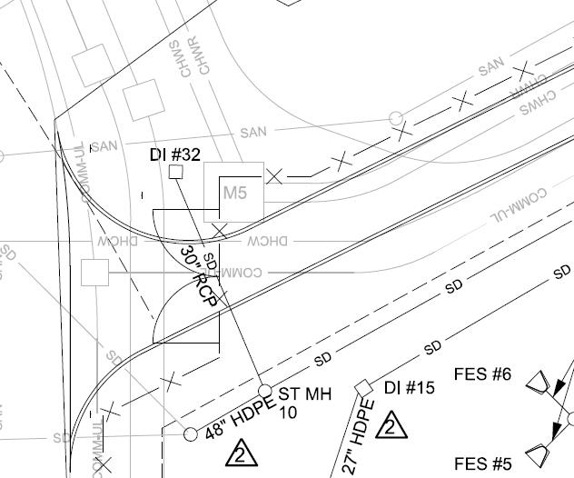
Original Design – Drainage run in question is DI32 – SD10 running under the road.
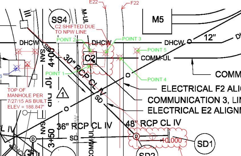
As built showing shift in ductbank centreline
Solutions I was able to proffer were move the drainage run run to the East of the ‘M5’ structure or change the inlet type. Both solutions would require re-design / confirmation by the designer because of the potential changes to the drainage areas, and requirements for confirming flow and velocities in the amended drainage runs. The first option was ruled out fairly quickly when I looked at the elevations of some of the other utilities in the area and realized that the pipe would have cut straight through some other utilities which had already been installed. Option two was therefore looked at more closely. The designed inlet was an overflow type, quite common here and usually seen in bio-retention ponds.
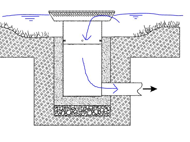
Typical inlet sketch
This inlet type meant that water would pond until it reached the inlet level, then enter the drainage by falling into the inlet chamber and on into the pipe where it is carried under the road (see original design above) and into the drainage system. It was the drop into the inlet chamber which was part of the problem here. By changing the inlet to a culvert instead the same function is achieved, minus the initial drop in elevation. Negating this drop meant that the drainage run could now pass over the ductbank, which it was previously conflicting with. See sketch below using, made using information from the as-builts and design drawings.
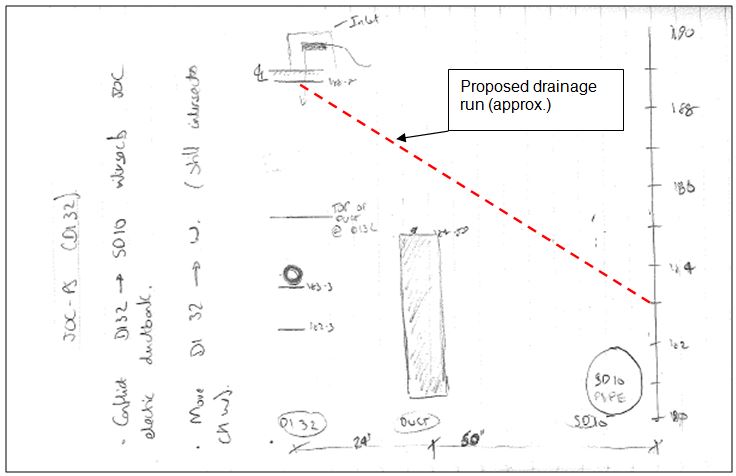
Sketches from notebook
I proposed to the designer that the inlet design was changed and calculated that a gradient of around 5.5% would maintain the original designed invert of the pipe at the SD10 (see picture above) This meant that the manhole structure which had already been delivered to site wouldn’t need to be changed. Any more than 8% would conflict again with the ductbank. Steep then!
The design came back from the designer yesterday:
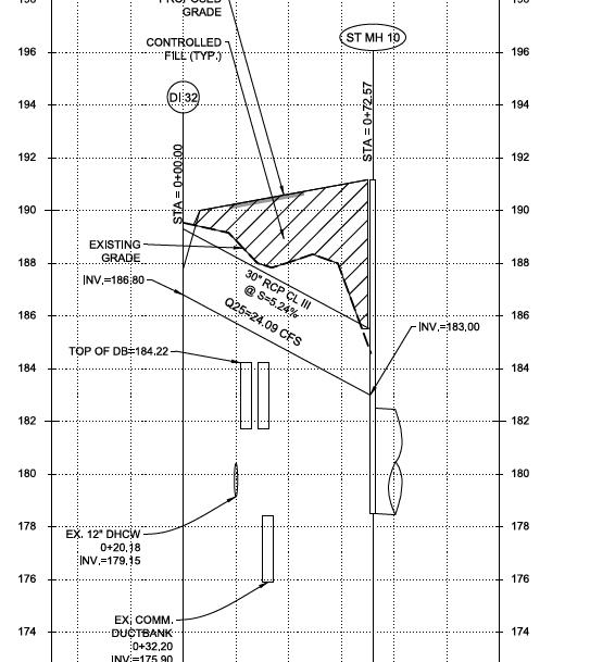
Approved design
Its hardly ground-breaking stuff, but it does throw up some pertinent issues. Firstly the obvious deconfliction of adjacent projects. This has been a near constant issue, and one which has caused some contractual variations. Clearly the best way is to do it early. In this instance it can be seen that information about the location of utilities were made clear to the adjacent project, however in squeezing in a drainage run between so many utilities the adjacent project has been burned by, I guess ‘unforeseen ground conditions.’ (ie the ductbank wasn’t where they were expecting it to be). Second the fact that the client on my project has the requirement to harden utilities. I gather that it is far from standard practice, but concrete wrapping ductbanks in areas of high utility/ services congestion adds to the complexity of installation. Predominantly this is because of the space required, but also it takes much longer and costs a lot more. I’ve been able to make a large saving (I blogged about it earlier) by questioning the requirement to harden some of the less critical utilities here. There is also the question of maintenance? In any case, in this instance the client would not have given latitude to remove the requirement for hardening, and so the conflict will always have arisen. There is however a minimum level of cover to be observed on ductbanks when they are close to the surface. Perhaps if this was applied to those at a deeper level, as a sort of ‘fudge factor / buffer zone’ then the designer might have been constrained at an earlier time in the project and might have arrived at the culvert solution in the first instance.
