Thames Tideway Tunnel – The start
Thames Tideway Tunnel – The start
I have now started on Phase 3 with Arup and am working within the geotechnical team on the Thames Tideway Tunnel project. To avoid this blog getting too long I’ll present some of the background, my part in the plan and a brief discussion on sustainability.
Background. The London sewer network is predominantly a combined foul and surface water system. The sewers convey the waste to treatment works for processing. However, when it rains heavily the capacity of the sewers is often overwhelmed and the excess sewage is deposited into the Thames through combined sewer outfalls. To reduce the frequency of incidents of raw sewage discharge into the Thames each year the Thames Tideway Tunnel project aims to capture combined storm and foul water within a new 7.2m diameter tunnel running from Acton in the west to Abbey Mills in the east.
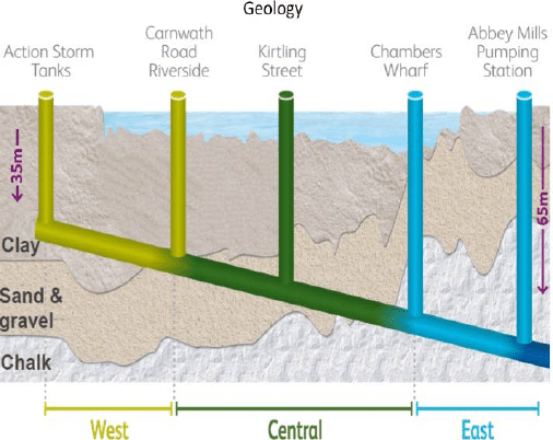 Overview of tunnel alignment through the London geology.
My part in the plan. Effectively the project is divided into three sections: west, central and east. Each section has a number of connections to capture the existing combined sewer outfalls and convey the flow into the new sewer. The process is generally to have an interceptor chamber which feeds into a further set of chambers to attenuate flow and then a drop shaft to connect to the new sewer. I have 2 sites to design the foundations for: Putney and Barn Elms. Arup are not responsible for the main sewer tunnel or drop shafts but are responsible for designing the other elements, including the chamber and connecting culvert foundations.
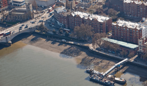 View of Putney Foreshore Embankment site
Putney has some interesting challenges: The connection to the existing sewer outfall is directly below Putney bridge. One of the proposals sees there needing to be a number of bored piles in the foundation design (questionable reasons: either as tension piles to avoid buoyancy issues or to minimise long term settlement between existing bridge outfall and new structure). Getting a piling rig into position will be a challenge due to headroom constraints. One method sees a temporary sheet pile wall planned to be installed around the whole site area (under the centre of one of Putney bridge arches (max headroom)), then dewatered, excavated and re-filled. The temporary works are out of my scope but understanding how the contractor will carry out the works is clearly important.
 Existing outfalls (left), proposed interception chamber on right – this is 7m deep with a number of bored piles within the foundations proposed!
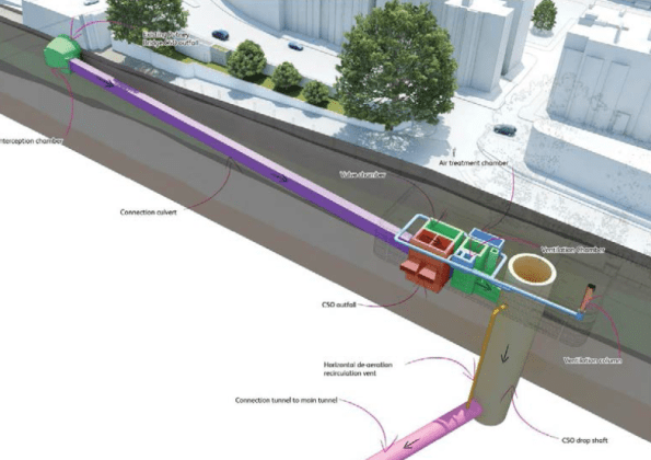
My responsibility is designing the interception chamber (left green), connecting tunnel (centre purple) and attenuation chambers (right brown/green/blue) foundations. Drop shaft and connecting tunnel to main sewer (out of picture) is not my responsibility.
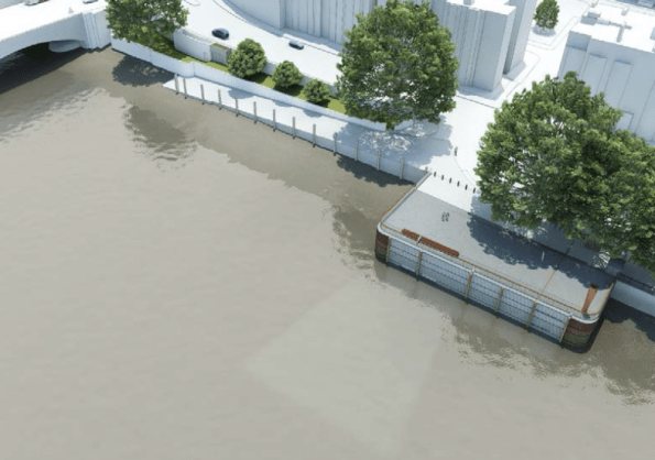 Illustrative view of completed site.
So in terms of what I am doing – initial work is scoping further ground investigation for where there is risk – lack of confidence in certain parameters for example. Next comes a geotechnical design report and then will come developed design, detailed design and finally construction issue information. This aligns pretty well with the RIBA stages of work too.
Sustainability.
The aim of the project is to provide overflow capacity to the existing sewer infrastructure in order to reduce the frequency of sewage discharges into the river Thames.
Advantages and Disadvantages. This project will bring political and social benefits of a cleaner river and evidence of better waste management practices within the UK. The economic benefit is more questionable. Construction costs have multiplied by a factor of 3 from 2005 to £4bn raising the question of its cost worthiness. Moreover, other options of attempting to use land as attenuation (green field sites as soakaways, green roofs) through green infrastructure have been argued to be sufficient to meet the demands of future predicted storm levels. The legislation is in place to enforce greener infrastructure but it appears planning authorities do not follow this through as judicially as they might with greater resources.
The accuracy of the sewage over flow statistics has been questioned, with some groups stating that the level of pollution entering the Thames is lower than the Environmental Agency’s limits now and so the construction of the new sewer is a complete waste of money.
As part of the project, the Beckton Sewerage Treatment Works will also be upgraded to cope with additional demand. The disadvantage of increasing the amount of surface and foul water captured will be the need to pump all of the water through 60m of head at Abbey Mills which will result in higher maintenance costs and require significant energy to achieve. If some of the storm water had been captured through green infrastructure assets there would be less energy required to process it at the other end. Reducing the amount of storm water ever reaching the sewer therefore brings a double saving.
Clearly reducing the sewage discharge into the Thames is beneficial and the project will significantly improve the condition of the river. I suspect as a country likely to be at the forefront of developing environmentally friendly solutions the green infrastructure piece will come but for now at least a solution has been produced to an acceptable cost, timeframe and quality, assuming all goes to plan!
In summary. This project will be my sole focus. I have started to investigate wider strands within it – financial/commercial for a better background understanding but with a company like Arup, unless specifically requested, phase 3 will tend to be focussed on one major project.

Thanks Damian, Nice to know what you’re doing – designing piles for the poo tube how full of double entendre life is! I’m intrigued by the C50 Outfalls shown on the finished item image whiuch suggest retaining discharge into the Thames. I would also suggest the 60m head at actone need not be so large if inverted siphoning were used i.e. the tunenel stand full but has a flow generated by pumping, which is from the base of the pump chamber shaft but with a positive pressure head.
Damian,
I think I understand the concept of putting the sheet pile wall in under the arch to create your site, but where is the site going to be to enable these works to take place? The aerial photo doesn’t look like there are many options.
Richard – Yes you are right. When the storm water levels exceed that which can be stored within the new system it will discharge into the Thames – as per current arrangement. I think I understand the hydraulic system you suggest – we might have to discuss that one a bit further.
Rich – Good point regarding space to actually do anything. I have just seen the temporary works scheme to undertake the works – it is impressive and far more extensive than the permanent works themselves. The idea is to construct two temporary piers around the interception chamber (next to bridge) and main works site. Most of the material movement: sheet piles, excavated spoil, concrete would come/go by barge and be craned into the excavation sites – therefore conforming to the “All by River” approach used as part of the planning submission. There was a plan to have a much larger sheet piled area to act as the working room for the sites but this seems to currently be plan B, with the temporary pier option favoured.
Do you know if there are going to be any intermediate lift stations?
My first thought would be that having two shallower drops with an intermediate lift station might be easier for construction, and for less complexities in Richard’s proposal. But because the tunnel hits chalk at the Eastern end does that make it easier to construct from a civil/geo perspective?
I don’t know much about the pumping stations yet so will come back to you. Chalk is not likely to be any easier to work in, especially as there is a deeper aquifer to contend with at that depth. The issue with chalk can be discontinuities I think – so some useful engineering properties but also big risks in pockets of weaker material.
I will add a really interesting point which is that getting the sewage into the main sewer via the drop shaft will involve a cork screw like channel to avoid the waste plummeting down vertically 30-50m which would cause issues for the concrete base.
Cork Screw Concept is fascinating. If the issue is impact damage I would have thougha simple wet well/catchppit chamber would have dealt with all potential issues much more cost effectively. If the issue is absorbing the impac energy in the foundation then disspating it over time with a corkscrew makes some sense buit begs the question could the enrgy be harnesed by a rotating screw generator. Energy pumping at one end offset by generation at the other!
Richard – seems the issue of dropping air entrapped water down 50m can cause 2 issues – impact damage from turbulent flow and a rebound effect where the water could be bounced back to the surface from the pressures generated within the entrapped air. The article: http://www.newcivilengineer.com/download?ac=1267456 presents a summary of the hydraulic challenge (Page 10). The solution seems to be a vortex inducing culvert connection to spin the sewage to keep in laminar (to reduce entrapped air) with landings at the base to reduce erosion.
There is no talk of any energy capture from the potential energy available from the series of drop shafts. I presume this was discussed earlier in the project and a simple, but perhaps expensive, solution adopted. I don’t know the cost balance between a series of hydroelectric turbines in each of the drop shafts needing maintenance themselves and the electricity they would create with a somewhat uneven flow (although this could be smoothed). Likewise I don’t know if the client paying for the construction works is the same as the one that will pay for the running costs in the future, I suspect they are not the same.