Bedding In – Ph3
I’m in my second week working CH2M (previously known as Halcrow) working for the Ports and Maritime Division and suprisinly…I’m enjoying it!!!
I don’t intend to go into any detail in this blog but rather set the scene and prompt questions should anyone have any.
I have joined the Queen Elizabeth Class (QEC) project which is designing the dock that will birth the new aircraft carriers in Portsmouth. DIO are the client and VolkerStevin are the contractor.
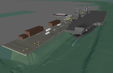
The dock is an existing 19th century sea wall with a 1930s and 1970s series of jetty attached to it. The water depth alongside the jetty is sufficient for the new boats however, the jetty capacity is well below the new requirement.
The key loading on the jetty platform will be :
Vertical – bogie point loads from the mobile cranes. The jetty will also house a new M&E shed that will house all of the ‘wizards boxes’ used to generate the electrical feed required for recharge (these are pretty big and heavy). Finally, the jetty will be expected to support lorries and container stacks all over the place.
Lateral – the boat hitting the dock when it parks (technical term), 100tn.
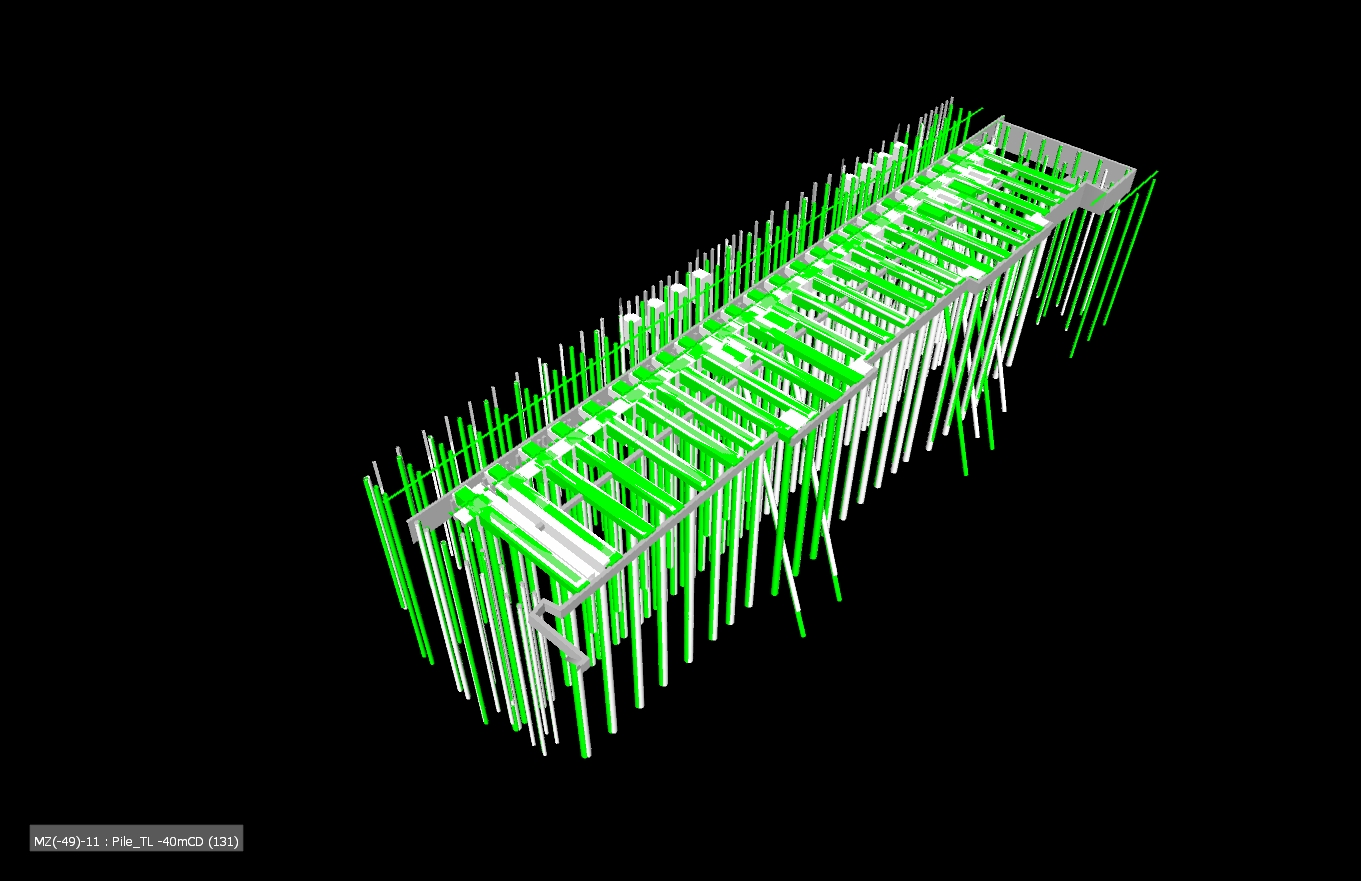
The plan
– Two large section of the jetty deck will be demolished and rebuilt.
– One strip of the deck will be cut out to allow new piles to be threaded through the existing.
– A number of holes will be cut out to allow new piles to be fed through, many racked to facilitate the lateral loads.
– 2m concrete deep beams will be inserted under the deck across the top of the new piles.
– Pre-cast slabs will fill the holes.
– A new deck will be cast in-situ to thicken the whole deck with a single in-land crossfall.

Grey is existing, green is new
ICE CPR
Two of my identified weaknesses when moving to Ph3 were technical design/analysis and working with existing structures. I think this project will serve me well!
Remove the reins
My first job has been to conduct a shear check between the existing and the new decks where the mooring bollards are located. The bollard rating is sufficient and the bolting down design has been verified but it was unknown whether the deck would simply rip apart. EN 1992-1 has a section on concrete poured at different times so that became my starting block however, it assumes the shear failure would occur due to bending so attempts to use the lever arm from the bottom steal to the shear plane (it assumes you are looking at a composite beam and slab arrangement). I knew this made no sense and after a long time (a very, very , very long time) I realised what the problem was and substituted to for F/A. The rest became code bashing exercise of mumble jumble Greek. The key take for me is that I knew it wasn’t right and knew where to go to sort it out. That may sound like a small thing but the kudos of presenting output without direction on my first tasks seems to have served me well and boosted my confidence for the next six months!……….Who’d a thunk I could produce a calc with Damo’s help 🙂
In other news
My office has the design contract for the Middle East Basing (think Op Shader). I was asked to look at a deployment order to send some CH2M Engrs out for technical design support to delivery. Page two of the doc had the CoC outlined and OC STRE sat at the top of the tree…like a slap in the face I was reminded of my day job after this process ends.

Sports and Pastimes, you’ve landed on your feet there. Just looking at the 3D image is the dock channel going to have to be deepened to accept the draft of the new big boats? Also who is your client, is it the MoD? If not are the MoD funding it in any way do you know?
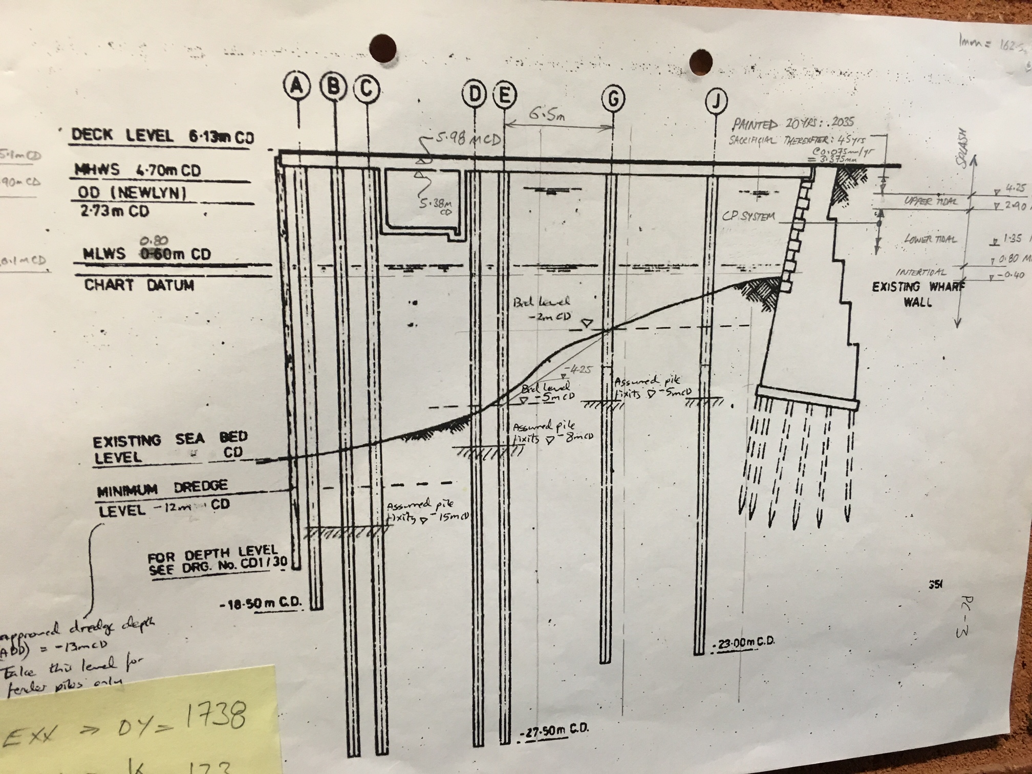
Both the channel and birthing location are deep enough. After Christmas I will be working in the design for the navigation lights. They are basically a single pile that extends >30m above sea level which makes for one very long steel tube. The problem with these is that they sit in the deep channel that the boats use.
I only know the client as DIO. At this stage I don’t fully understand how the money works but I do know that my design PM often meets with a Navy 2* for variation and change orders to be signed off.
Hi Olly – what sort of piles are going to be used for the jetty? What extra considerations are needed considering the marine environment? Are the number of extra piles going to pose group effect issues if spacing is less than 3d if some are replacement? Is the contract with DIO a traditional one?
Hi mate – The contract is bespoke. I am lead to believe that much of it resemble an NEC3 however, there are differences. I’ll leave it as that for now and cover it as a full topic once I’ve had time to fully get my head around and understand the implications, good and bad!
The piles are 780-900mm CHS up to 30m (racked) below ground.
To put it bluntly, the piles have been a nightmare from what I’m told. In a future blog I will post a plan of the deck which is a bit of a patch work mess of holes, slots and new areas. The load combinations run in to the 1000s and cover all stages of construction and use. The Staad Pro model too over 36hrs to conduct it’s first run!!! Since then, the low risk load cases have been removed and now it takes 5hrs per run. Arup are the independent checkers and one simple discrepancy takes three days to resolve (change model, run calc, assess and communicate).
The piles were designed in groups, critical and large groups first. They were set out in grids to try and deconflict with the existing piles and then moved as a group and tweaked individually until a group worked with in the knitted structure. The biggest headache were the racking groups as the spaces was very tight. To try and negate the overall draw down of old and new groups, new piles, on the whole, extend much deeper than existing and carry the party share of the loads. In some cases the existing piles will be disconnected (a slice removed) from the existing deck to as they are too close to new ones.