CCB – Phase 3
I started to transition to phase three very shortly before Christmas leave. I factored in around 6 full days of sitting at the Baltimore City Crescent Building (CCB) split over a two week period to settle. This would allow me time to meet and greet; sort out a desk space, IT and scope out the work. Amazingly it only took around half a day to sort out IT and I had a desk space waiting for me, which I gather is at odds with Henry’s experience. For me transitioning 3-2 has been much easier than 1-2. I started full time at CCB on 4 Jan, however have retained my access cards to site so I can go and get ‘a cheeky shufty’ before departing the States.
The Structures team I am working in now sits in a different Division to the Construction Division where I was previously housed and is physically sited in the Baltimore District headquarters building in downtown Baltimore.
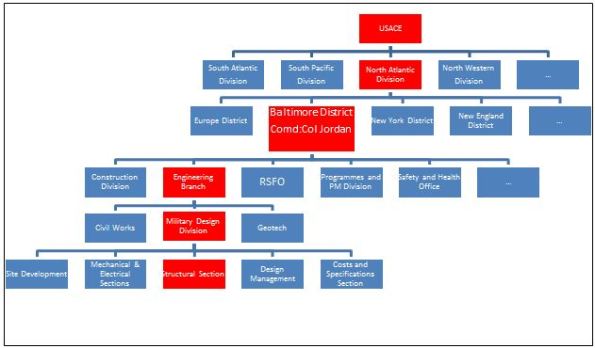
USACE Organisation
The figure above shows the organization, with red signifying where I sit. The Area Office where I was previously working was, like Henry’s, part of the Construction Division. Phase 3 sees me shift to the Military Design Division, which is a part of the Engineering Branch. Rather confusingly for a military organization the term ‘Division’ is no indicator of the position of the department in the hierarchy; Construction Division and Engineering Branch are equivalent departments, Construction Division and Military Design Division are not.
The Engineering Branch is responsible for the procurement, design and overall project management of federal and publicly funded projects. This is different to the Construction Division, who physically executes the works. Civil Works deals with levees and dams; Military Design deals with new construction and refurbishment projects; Geotech deals with geotechnical analysis, design of foundations and soil testing.
First tasks as part of the structures team include gathering an appreciation of the work available, described below, and becoming familiar with the US design codes and their application. Where opportunity and time permits I also hope to take on small portions of work from the geotechnical branch and site development (civils) team. This is fairly usual for the USACE placed students.
Below is the breakdown of what has been proposed so far.
Fort Lee Training Support Facility, Virginia. This is a $33m project which will be procured on a traditional contract with USACE conducting the design. It being undertaken by the Baltimore District, despite the site being situated geographically in the Virginia District. This is because Baltimore District has capacity whereas Virginia District does not.
The training facility requires a largely column free 120,000 sqft footprint in which various military artefacts and exhibits can be housed and moved around, depending on training requirements of the end user. As well as lecture theatres, toilets and workshops, associated with typical training facilities, there is also a requirement for an armoury, which must conform to its own set of construction standards. The training facility project could be defined as a museum, however because this would invoke more stringent, regulations and because it is not open to the public this is not the case. The requirements for humidity control and airflow are however being taken from museum standards in order to ensure the protection of some of the more delicate training aids and artefacts. The requirements for the movement of training aids, some weighing up to 90T also means that the typical reinforced concrete slab on grade (ground slab) has certain strength and ‘finished flatness’ requirements so will be designed more like a pavement, similar to runway design. It can be seen therefore that the design of the training facility allows for some freedom in the selection of which standards apply.
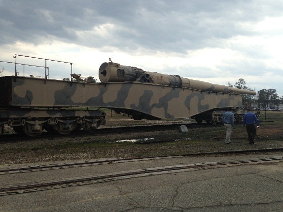
Example Training Aid
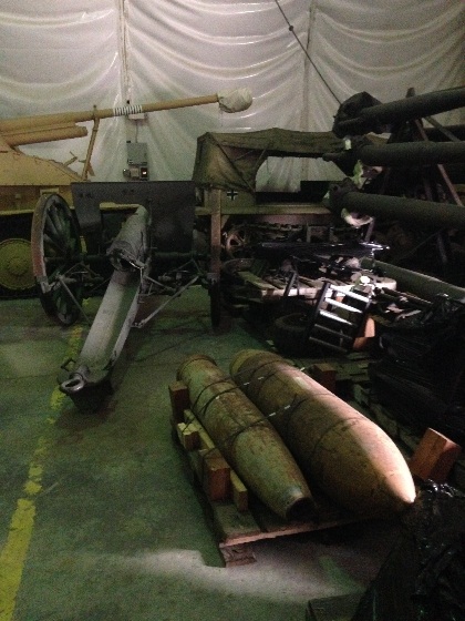
Example Training Aids
The project is at 65% review stage, however is recognised as being more like 30 – 40% complete. This is mainly due to issues with the completion of the Site Investigation (SI) and subsequent Geotechnical Design Report. This was sub-contracted out, however issues with the scope meant that the SI required completing twice as insufficient information was gathered first time around. A comprehensive GDR for the project is still forthcoming, however for the purposes of project progress assumptions have been made about the bearing capacity of the soil. This means that a large risk to the project lies in the ground conditions since design is being based on assumptions which have not been fully verified. This has the potential to increase the project costs to the client at the execution phase and highlights the importance of a sound scope for the SI in the first place.
The site itself is a forested marshy area, which has been largely created by surrounding projects, which have drained their sites into the proposed area. It slopes across the length of the project causing an 11’ elevation difference between one end of the training facility and the other. At around 30’ depth there is a thin highly compressible clay layer. This makes the project susceptible to long term continued settlement issues, in particular due to the large surcharge placed on the ground due to fill the fill required to level the site. The current design stipulates that shallow foundations should be adequate, which surprised me on hearing the outline ground conditions.
The requirement for open space means that the proposed steel construction will not be braced. Instead a steel portal frame design is chosen. Spans of up to 60’ mean that both standard and built up girders are insufficient and so a truss system has been chosen to try to maintain ‘a lighter appearance to the members.’ The sizes of the outer faces of the building mean that lateral wind loading and seismic loads are high. This means that the moment connections and details require careful consideration to ensure that lateral loads can suitably be transferred through the trusses into the columns and foundations.
My responsibilities will be to assist the lead structural engineer with verification and detailing requirements. I will also be involved with the shallow foundation design. The 95% design submission is due in June 16.
Building 8607 Renovation, Ft Meade. This is a design build project and so USACE is only required to produce the technical specifications and tender documentation on behalf of the client. Because there are Anti-Terrorism Force Protection considerations (ATFP) it is, however, likely that there will be some more focus paid to conceptual design. This may extend to some initial element sizing and direction as to which ATFP approach is suitable I have been told to get a software license for STAAD Pro to assist with a bit of modelling to test assumptions that go into the specification (so thanks NJP).
The project scope is to turn existing accommodation buildings into administrative space within the existing Ft Meade camp. The tender documentation is required to be complete by mid Jul 16. This is likely to be background work in addition to the main training facility project described previously.
Access Control Point, Ft Meade. This is a $20m project procured on a traditional contract with USACE conducting the design work. The requirement is for a fairly generic access control point to be installed at Ft Meade, consisting of several inspection lanes and indoor areas for security staff. The inspection lanes are simply steel hollow section columns with steel deck canopies spanning across the point of entry. The canopies won’t resist lateral forces and so essentially the steel columns will resist gravity and lateral forces as cantilevers. The indoor areas and inspection lanes also require to provide some element of protection for security staff and so will require design for impact and ATFP.
Other. As stated there may also be scope to grab some civils work from the Site Development team. They deal with horizontal construction such as pavement, storm water drainage etc and could be good for some additional sustainable development exposure as well as exposure to a broader range of engineering. This combined with the different structural projects which are at different stages of design should provide a fairly rounded design experience.
In Other News

Mike O’Callaghan–Pat Tillman Memorial
This…
and this.
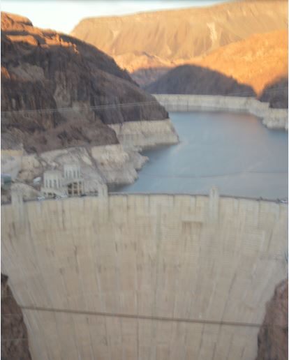
Hoover Dam

Welcome to the CCB. I think I expected the worst with respect to my transition to Phase 3. Apart from having to find my desk from under the ‘filing’ it had been used for and getting a lot of software I was up and running pretty quickly logistically. Having the flexibility in my working has more been about being able to close out my project up in Harrisburg, though it appears it’ll over run some more anyway! Like you I definitely found the move to Phase 3 much easier than Phase 2, predominantly due to understanding the organisation and being in the IT system!
By the way, Dunkin’ is closing down so we’re going to have to find an alternate outlet for ‘tea and donut’!