Revit Padawan
This week has been my first real foray into Revit and the force is not strong in this one. Below is the product of 2 days of hard fought CADing; it’s a good job I’m not billed out by the hour! The model is the ductwork and Fan Coil Units (FCUs) in the accommodation element of the NCO Academy. Blue is supply, Orange is return and green is exhaust.


All the duct work is sized using my new friend the ductilator. It certainly makes the tiresome job a lot quicker and easier than calculating them mandraulically! The flex duct connectors at the ends are basically cheating. However, as we have only just exited the 35% gate I’m sure there are plenty of movements to come and these allow elements to be moved independently without Revit dropping its fill. This is especially true as the zoning of the interstitial space has not been worked out yet. As appears to be commonplace we are waiting on structural to finish overdesigning beams before we can get into the important work of cutting holes in them.

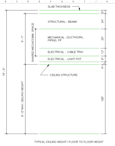
On a more serious note the building was originally conceived, presumably by the architect, as being 18ft floor to floor. Ignoring the training room, and its 12ft ceiling, that will no doubt be the subject of a blog in the future; the remainder of the rooms had a mixture of 9ft and 10ft ceilings. This translated to a 9ft interstitial space in some of the rooms, something which laboratories would be proud of. Arguments about leaving it alone were that the cost of brickwork wasn’t much when weighed against the time, and therefore cost, of trying squeeze everything together. My counterargument was sustainability bringing a big fat tick in the E3 box. I was thinking of the carbon output but to translate it into ‘American’.
To back this up I did some very rough calculations in Carrier HAP (Hevacomp equivalent) which showed that on a summer design day the cooling load would reduce by 2.8% and on a winter design day the heating load would reduce by 7.3%. Sadly, due to the way LEED savings are calculated this doesn’t translate into extra points for design, however it is good for life time running costs.
So the compromise is set to dropping the floor to floor height to 16ft which, across both floors, saves 4ft. The negotiated allowances for each discipline are shown below, though the electrical engineer has agreed to let HVAC enter his cable tray allowance and he’ll work around it; sensible. Everything is conservative at the moment so maybe we will be able to shave a little more off. Although clearly the model is getting ever busier and so unless the height savings are significant I shan’t hold my breath.
In other news I’ve found someone else that uses John’s calculators.


Henry,
I’m yet to have conducted any REVIT training, it’s on the to do list, but interestingly I am currently going through the process of requesting CADing of my concept mark-ups for the Vetwest project. So far I have done QA for the hydraulic design and round one for the mechanical, no-doubt there will be more. Chatting through the CAD process, due to my current lack of knowledge, I’m told the mech components take precedence with any hydraulic pipework running as close to the underside of the floor slab as possible with the electrical cable trays etc running beneath the ductwork.
My CAD requests have been done by two CAD Jockies (doesn’t sound so degrading as monkey) and so in understanding how each knows what level to CAD their service at, supposing they are doing so concurrently, I was told they stick to generic layer levels. I can see how this works in avoiding clashes (to an extent but not full proof) and then ‘bingo’ I could see how BIM, in particular Level 2 – collaborative working, would massively save on time and cost as both models, for example hydraulic and mech, could be worked on simultaneously and the previous design layer levels would become redundant for real-time intelligent design allowing services to be designed side by side (rather than on top of each other) but still avoid clashing. Clearly there’s more to it than that but you get the idea.
Oh and you can definitely bank on needing some of that upper structural real-estate – 24″ is a lot. An average 2m ceiling void is about right, not unlike my project that is a double story building but only a ground floor therefore boasting a ceiling void of 4.6m at its smallest – think its going to have some very long ductwork/cable tray hangers.
Fran,
I would say the precedence would be structural, drainage, duct, light fittings, water and cabling can go anywhere. At the same time everything can be negotiated and I imagine our drainage, for the upstairs bathrooms, will be kept within the structural zone.
When you say ‘generic layer levels’ do you mean levels as per my figure or just the different layers in CAD? I haven’t seen any clash avoidance buttons as such yet but am just designing to an offset to the floor level at the moment as the architect hasn’t lowered the building yet.
As for training, I think it is pretty intuitive, if you have a project then just get stuck in and shout for help as required. I have operated on Mark’s Hevacomp ‘office based teaching’ principle. also, unlike Hevacomp ‘Ctrl + Z’ works!
Henry,
Agreed structural would take precedence, that’s why it is seen as a given before you start designing in your various services. I mean the layers in CAD. I also don’t think there is a clash detection button in REVIT per se. It’s when you import several models into 3D viewing software like Navisworks that you can run clash detection.
Edit – a 2m ceiling void is big. An office space is on avg between 0.5 – 1m.
Fran, I’m not sure if I understand your comment about BIM. Even when working on the same model concurrently there surely needs to be agreed design layers or you’re going to get clashes all over the place when the model is synced. My experience on site was that the major downfall of BIM was that companies generally don’t pay to model drops, so you get additional clashes, and what looks great on a model may be a pain / impossible to build in reality. When you talk about hydraulic pipework is that Australian for public health?
Rich, I think layers are important to start off with, but if you are going to be efficient with space then you need the ability to work beyond that in tight areas. As with battlespace though its about coordinating those over boundary intrusions. I think this is where some of the issues come into play in construction as designers appear to like to work in their bubbles a little too much rather than communicate the issue.
Rich,
Henry touched on it. Working in your own layer, as you’ve always done as a CAD jockey, doesn’t serve to produce the most efficient design in terms of space. Where BIM helps is in the CAD jockey’s ability to work in 3D and see potential clashes as he goes. Where it falls down, as you’ve experienced, is when once the designers have handed over the individual BIM models to their respective services contractors and those contractors don’t have the ability to see other services because they are just working in REVIT without the BIM collaboration, you get clashes when the individual models are federated into the latest singular model. So in a nut shell, everyone; suppliers, designers, construction contractors and facilities management need to be working at Level 2 Collaborative BIM. It’s this culture change to procedures and processes that will see companies realising the full benefits of BIM.
Henry,
If you could add a couple of feet to the ceiloing void you’d make provision for future expansion with a mezzanine floor as long as we can compress the exessive space allocated to pipes and wire things!
True Richard. Although they have a training room that is going to be used for two hours a day and an auditorium that is going to be used for about two hours a week. So, rather than look at expansion, I’d be looking at bringing it all down to a one storey building with some more multi purpose spaces. However, what the client wants…
On that point it is interesting that we fight for LEED (BREAM equivalent) points here and there for system efficiency etc. However LEED doesn’t really take into account how much ultilisation the square footage is actually going to get. In this case I would argue the building is going to be heavily underutilized and so from a sustainability stand point this should be taken into account.
Oh and I’d seen Tim’s post, which was why when I was presented with my own one I actually knew what it was!
Forgot to say – go look at Tim Boorman’s post of 30/1/2015 – recognise the photo?
Henry,
Good to see you’re having fun with Revit. I am billed out by the hour and hate to think how much a client is being charged for me to draw badly. Am I right in thinking this building is a training facility with classroom? Do you have to work to specific guidelines for teaching environments in the US? Is natural ventilation ever considered or is your RH too high?
Rich,
The building has accommodation; the training room, for which we are using gym guidelines; offices and classrooms. So in short, yes. We are currently planning to use natural ventilation in the training room in the summer but other than that everything is conditioned in one form or another.
The reason is really the wide variation in environmental conditions, of which humidity is one. But the more significant factor is probably temperature. Out here it is pretty commonplace to have no heating emitters (radiators) in a building and everything is heated and cooled by forced air. I am designing a radiant floor (underfloor heating) in the training room, but everything else is heated by forced air.
In terms of comfort conditions I don’t think it is very good personally. If you want the specific standards I can dig them out for you.
Fran, when you talk about BIM and Revit as different things that clouds the issue slightly. Our whole building is being designed in Revit, so I can see everything if I turn on all the layers.
Word press is not playing ball and cut and paste turned words in to upper case….
HENRY, THEY ARE DIFFERENT THINGS. REVIT IS THE CAD TOOL AND BIM THE METHODOLOGY USED IN PROJECT DELIVERY. BEING ABLE TO SEE THE ‘OBJECTS’ OR ‘FAMILIES’ AND THE PARAMETER FIELDS ALL FILLED IN, I.E WITH GEOMETRIC DATA, MOVES THE MODEL UP THE LEVELS OF DETAIL (LOD) THUS MAKING IT EASIER AND QUICKER TO CONSTRUCT FROM.
No need to shout Fran 😉 I missed off the word model after BIM. What I was getting at is that it is the collaboration rather than the specific software that appears to be important, as Revit has the functionality to allow that collaboration. Having not worked on a construction project with BIM I am probably wading out of my depth though on the terminology and technical detail.
Fran,
The issues I encountered weren’t due to subcontractors using REVIT and then that information going into the federated model. They were caused by thinking that because the model doesn’t show any clashes everything will be fine. The reality is not everything is in the model and you’re going to have to rely on the accuracy of the guys installing it. Although a lot of problems are eliminated by using BIM, and there is the opportunity to make more efficient use of space the threat is that the design is overly sophisticated and therefore difficulties are encountered when it comes to building.