Oz NDY – Return Air Plenum Issues
Introduction
Prior to Christmas I was given an interim task to investigate complaints of doors being hard to close with loud whistling noises coming from the plantroom door on level 4. The project is a typical tenancy office fitout with construction complete and the office space occupied by Synergy staff.
I was given an initial steer by the project leader; his view being restricted Return Air (RA) flow to the AHU.
Background
The design of the floor (slab to slab) uses the ceiling void as a large RA plenum. The plantroom, containing the AHU, acts as a large mixing chamber mixing the RA (from the plenum) with the Outside Air (OA), which enters through louvers in the skin of the building. It incorporates a CO2 monitoring system that controls the motorised louvers to alter the amount of OA required to keep CO2 levels within permissible limits.
The main floor space is split up in to a number of offices (various sizes) and larger open plan areas. To reduce the chance of cross-talk between these areas full-height partition walls were constructed. Whilst this met the acoustic requirements it created a subsequent problem; the RA was being severely restricted in its attempt to get back to the AHU.
To resolve this, the design incorporated the use of Air Transfer Ducts (ATDs) installed through the partition wall. ATDs are essentially fitted into a rectangular cut-out in the wall and consists of standard metal ductwork lined with acoustic material. This allows both air flow through it and simultaneously reduces carried sound, as shown in figures 1 and 2.
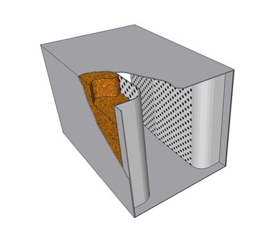
Figure 1. Basic ATD with Acoustic Lining.
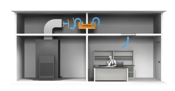
Figure 2. ATD in Use.
Identified Issue
A typical problem found in RA systems, that utilise a plenum rather than a ducted system, is not enough RA finding its way back to the AHU. In this case the number of installed ATDs is insufficient to allow the correct amount of return flow and is creating positive pressure build-up. Effectively, the mixing chamber (entire plantroom) is being starved of its required RA (under negative pressure) and the CO2 monitoring system, not seeing excessive CO2 levels, won’t allow any more OA in. Therefore, the only available air remaining is from outside the plantroom in the corridor (which is under positive pressure) and is now being sucked (willingly) into the plantroom and creating excessive whistling noises. Figure 3 shows a basic sketch I drew to aid in visualising the situation.

Figure 3. Situation Hand Sketch.
What’s possibly exacerbating the issue is the CO2 monitoring system. Because the RA is being restricted the CO2 monitor is most likely reading low CO2 levels, therefore signalling to reduce the OA intake as it’s not required to dilute the RA. This then creates increased negative pressure inside the plantroom and thus makes it easier to pull in air from the corridor due to the AHU fan demand. It then become a vicious circle as this extra air being pulled in from the corridor is most likely to come directly from the SA grilles, with little human traffic, meaning the CO2 levels will low.
Depending on how much the RA is restricted will determine the severity of the symptoms found.
During construction there were a number of design changes, doors being relocated and the like, which caused the air flows to change slightly. This however, is not deemed a significant reason for the symptoms being experienced.
Resolution
The resolution quite simply requires increasing the number of air passages through the full-height walls. As stated this had already been designed for and implemented through the use of 5 No. ATDs, however, clearly more are required. Figure 4 shows the drawing mark-up with existing ATDs (blue) and my proposed design for additional ATDs (pink).
Previous Resolution Attempts
The mech contractor had already attempted to solve the issue by cutting holes in certain locations within the full-height walls. While this may have helped to alleviate the issue, it has not solved it.
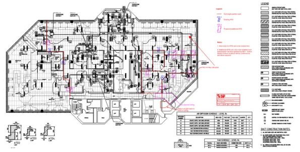
Figure 4. CAD Drawing Mark-up.
Design Calculations
I conducted some basic calculations to determine the number of ATDs required, allowing the same rate of return air flow as that being supplied to the floor space, resulting in a more favourable neutral pressure.
The calculations included splitting the floor space into sections, boundaries based on the full-height partitions, where I then added together the SA from each diffuser in that section. I then worked out the area required (using Q = A x V based on a 5 m/s air velocity) to get that flow rate through the wall to the next section. I continued the same calculations for the other sections, remembering to carry through the flow rate from the previous section as the RA from the entire plenum space is trying to get back to the same point (left to right when viewing the dwg).
In total I calculated an additional 9 No. ATD2’s (600mm x 400mm) were required. In truth it’s only the cut-out dimensions that are actually required to solve the air flow issue, not the ATDs per se.
Design Considerations
There are important factors in positioning ATDs within a plenum: availability of space between the upper floor slab and false ceiling, space between other services, and understanding the use of the rooms either side of the full-height wall to name the most important. All these were considered in my design. The last consideration, the use of rooms, is particularly important as this could determine the possibility of negating the need for ATDs in a particular location altogether. That is not to say there wouldn’t be a cut-out, just no ATD installed, so still allowing the required passage of RA.
COAs
Two COAs were considered, with time, cost and quality in mind. However, before the suggested COA is carried out a number of RFIs must be answered by the mech contractor, these are: confirmation of the location and size of previously made cut-outs, and an estimate on the availability of space to install the ATDs. The location and size of previous cut-outs is important as these could be utilised and potentially increased, based on the calculated sizes above, as suggested in the COAs below.
COA 1
This would be conducted in two stages, both during out of hours so as not to disrupt staff working:
Stage 1 – Make the cut-outs in the full-height partition walls as indicated on the mark-up drawings. This should solve the issue, however may lead to excessive cross-talk. If the room pressures have been restored, the symptoms disappeared and there is no detection of cross-talk, or it is at an acceptable level, then the works will be complete.
Stage 2 – Assess the level of cross-talk, if it is not acceptable then conduct stage 3.
Stage 3 – Install the ATDs in the designated cut-outs, thus solving the cross-talk issue.
Pros and Cons
The main pro is: If stage 1 is sufficient there will be a substantial cost saving on negating the need for possibly all or at least some of the ATDs; each approx $1000 a piece depending on size.
The con is: If stage 2 is required then there would be extra labour costs due to the mech sub-contractors having to go back a second time to install ATDs.
COA 2
Do as COA 1 but all stages in one go.
Pros and Cons
The main pros are: Reduced labour costs for the mech sub-contractor and all the work being done in one go means minimal disruption.
The con is: The ATDs may be superfluous in solving the issue and therefore present an unnecessary cost.
Noise Level Consultation
I discussed the issue with our acoustic engineer and am confident that the overall cheapest option, that still achieves the required acoustic quality levels, is COA 1. This is based on not all the positions identified requiring ATDs. The exact number cannot be confirmed until a further assessment is conducted post stage 1 of COA 1.
Recommended Solution
The recommend solution is COA 1 but I envisage having to discuss these actions with the mech contractor, as alluded to, to get answers to my RFIs. This may also involve going on site to discuss further.
Update
During the preparation of this blog I learnt, through a third party, that the mech contractor indicated it wouldn’t be possible to fit the ATDs as proposed due to lack of space in the partition wall around the plantroom. There were some other suggestions mentioned, such as, installing a large transfer grille in the corridor/plantroom wall but this would need to be quite large to solve the issue and would likely look pretty rubbish not to mention noisy. It would then require an attenuator on the plantroom side to attenuate the plant noise. I think the next step is to meet with the mech contractor to discuss options.
What did I learn?
A key observation, which extends to all projects, has been that no matter who you ask for advice, you will always get a slightly different answer. The key principles will be the same but individual engineers’ will be basing their ideas on their accrued experience. I suppose this highlights the meaning of engineering, derived from the Latin ingenium, meaning ‘cleverness’ and ingeniare, meaning ‘to contrive or devise’, and just goes to show there is more than one way to skin a cat. The challenging part is to learn how and why these little design nuances can aid in delivering a more technically, sustainable and economical solution and therefore aid in refining your design skills. The technical solution also needs to be balanced with any political considerations, especially when wishing to win any future work with the same client.
I also learnt about the disadvantages of plenum based return air systems and found this article helpful in understanding:
In Other News
I organised a surprise birthday present for the wife; a great view of Perth from 1500ft. It included a shot of JHG’s PCH project and the new sports stadium, managing contractor being Brookfield Multiplex (new alternate Ph2 attachment). I’ve also included a few other snaps…
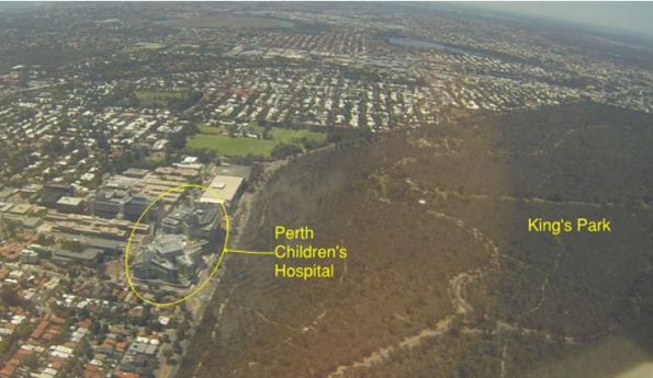
Perth Children’s Hospital.
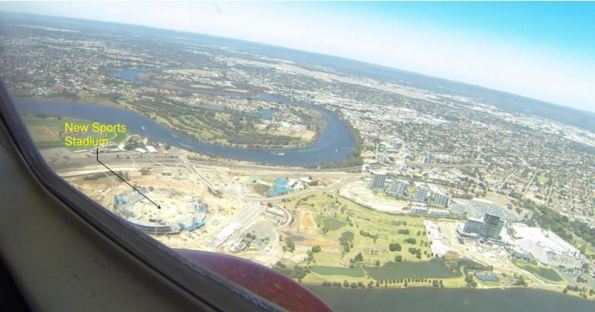
Perth’s New Sports Stadium – Still in the structural build stage.
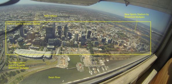
Perth’s Central Business District.
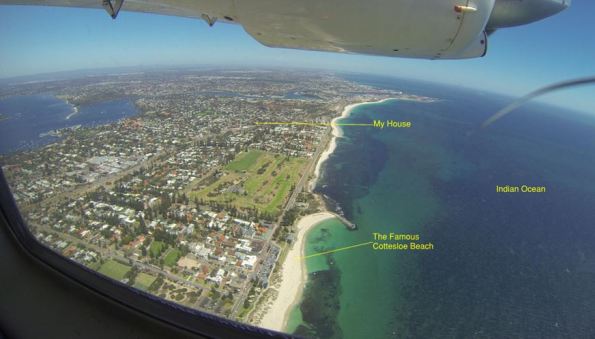
WA Coast Line.

Happy Wife Happy Life!

Hi Fran, nice project. Were the design changes at the start all approved or was the m and e design not right in the first place? Who has to pay for the costs of the remedial work, is it still in a liability period?
Have you had to do any computer modelling to prove your coa1 recommendation? Otherwise might be costly to start a solution if that was not the cause.
Damo,
As far as I know the partition walls were a variation. When that was designed in I don’t think they were fully taken into effect how they would alter the return air flow. We are still in the DLP phase but thankfully the client is on-side and I am told just want the issue resolved. As to who will pay? Apparently there were cost savings elsewhere and so they will use that.
No computer modelling and to be honest it’s a relatively easy to understand issue, which is a known concern with using ceiling voids as a return air plenum. Which begs the question ‘why wasn’t this considered in more detail?’ Therefore, the design team can easily attribute the problem to restricted return air paths through the walls. My solution may be a tad overkill as it’s based on a theoretical analysis but we are confident it will solve the issue. It may be a case of cutting holes in the wall one at a time and evaluate the results.
All this may turn out to not be possible until we can evaluate just how much space there is available in the ceiling void and between other penetrations through the walls.
Fran,
Are there any other issues being identified? Is the lack of designed RA path leading to a build up of CO2 in the occupied space? You mentioned that you considered space and services in your design, but the contractor has advised it won’t work in practice due to a lack of space. Do you think more time spent on recce would have identified that sooner or is it just one of those things?
Rich,
Good point about possible CO2 build-up. Nothing has been reported but then it may be difficult to assess that as a possibility. The contractor had attempted to make some cut outs but I haven’t yet had the opportunity to confirm where and how big. The solution incorporates these existing holes and nothing is to be done until they liaise with us first to answer the RFIs. The update, as of yesterday, came in via the lead engineer and it was only then did he mention the contractor didn’t think there was enough space – hence me prompting a meeting to properly nut things out and discuss options.
You certainly have a point about more time spent on recce, or more like better time spent. The issue here is no one from the FM side was there to meet us so we couldn’t even gain access to the plantroom. The other issue is that the building is occupied and so getting into the ceiling void at the various wall locations to have a nose around will disturb people. All easy to overcome issues but I’m not the one co-ordinating this – I was just a helping hand. Maybe I need to step-in with a little more forcefulness and get things moving…
The pain of not being able to see what you want to design, sounds familiar. I’ve got a number of labs that I’m providing steam to which are CAT 3. I’m not sure what that means other than the experiments in there are so dangerous / sensitive that it’ll put the lab out of action for 1 day just for me to have a 5 minute look and confirm what I think is going on. So the client is going to have to take a bit of risk on that element of the design.
I’ve been amazed by the lack of interest to recce. I’m working on a pretty big project that has at least 12 engineers from my office working full time but that easily doubles when other remote offices are taken into account. The amount of people who have visited site, have any idea regarding the context in which they are designing is frighteningly low. As a result, a huge amount of time is wasted by people design models or running calcs only to find out that things weren’t exactly how they thought. This failing is then placed on the shoulders of the contractor for not providing the detail but I disagree with this mentality(clearly I keep that to myself).
I’ve spent the last few days working on a methodology to pile below a concrete deck and fit pre-cast pilecaps (40tn concrete blocks) on top. I’ve been tasked directly by my consultant PM but it turns out that the work I’ve done wont actually fit because I was not presented all the constraints…in part, because the PM didn’t know them either.
Recce’s backed up with clear and fully distributed reporting is key!
Olly,
Agree with your view of how a simple recce can really make the difference in properly understanding the situation at hand which can only serve to ensure a better solution is delivered. The frustration is not being involved from the beginning and not setting up the first site recce we went on. However, as replied to Henry’s comment, we have a mtg tomorrow where I will now try and make some headway and fully understand what the mech contractor has done and thinks about it all.
We’re both talking about projects where we could visit, I think issue extends far beyond. My office works on global designs as I’m sure is the case for most people. At best we could have an RE on site but more likely it would early visits or contractors feedback.
For all of the military’s faults, I think this is something we do really well. When we got Mastiff all the bridges in Basra had to be checked as it was the heaviest vehicle that operated in the city. This process was pretty painless as the original recce notes had been well written, well maintained, supported by photo’s and updated when ever things when BANG whilst on or around them. Often, we (silly old inf) were trusted to conduct remote checks and feed back no different to a site engr checking.
My frustration is the poor dialogue throughout the team and the passage of sketches and such like. Maybe this is unique to my office and team but I suspect not.
Fran, I probably don’t fully understand the layout but I was wondering if increasing the door undercuts between rooms that have full height partitions might be a way of creating more airflow if you are having space issues in the interstitial space. I’m not sure of the acoustic implications and cost could go wither way depending on whether you can just whip the doors off and start planning the bottoms.
Also are were the full height walls only specified to improve the acoustics or was there a fire engineering element involved too? I’m guessing not if it was a variation as the design would have had to be compliant before then?
Henry,
Not sure I understand your view in increasing undercuts to doors. The issue is the return air in the plenum not the supply air in the space. Undercutting to doors will create more air flow in the space but I don’t see how that would solve the issue. Full height walls were just for acoustic improvements.
What I was getting at is that if the issue was between the individual offices and the open plan office then increasing the flow under the door will better equalise the pressure between the two. Also, you are providing a second pathway for RA from an individual office: under the door and then through the RA grilles in the open plan office. As the open plan office is bigger it is likely to have more capacity for RA and by providing an alternate pathway you are reducing the friction/pressure pathway for the air especially if you threw a couple of extra RA grilles in the open plan ceiling. I just thought it might a space efficient supplement if you are having issues getting RTDs into the interstitial space.
Ok, I understand now. What you can’t see from the dwg is that the main corridor doors (leading to the plantroom) are pneumatic and metal framed. No undercutting will be permitted here. Plus, if that did aid air flow it would likely be the cooler supply air (less dense than the warmer used air) that then flows back to the corridor before getting sucked in through the plantroom door. It still leaves us with low flow in the plenum.
Oh I also meant to ask are you concerned about the fan power at all? I assume without modeling, and not being able to get into the mechanical room, it is difficult to make an assessment and something that would be easier to modify in a later ‘stage’ as the work would affect the occupants less.
As you say without having been in the plantroom I can’t say what the fan is doing. I’ve jacked up a mtg with the client, project management and the mech contractor so hopefully we’ll get a better idea of things; or at least a plan to conduct a proper recce.