Archive
From Cowboys to City Slickers
-
Phase 2 – Completion of Chaffey RE Wall
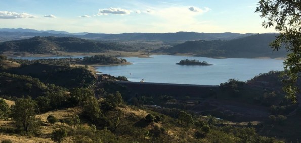
Photo 1 – Southern View of Chaffey Reservoir
In my last week on site at Chaffey Dam I was able to witness the completion of the final layer of soil placement after having laid the very first facing panel seven months earlier. The Chaffey Dam RE Wall was used to increase the crest height of the existing embankment dam to withstand the PMF for the catchment and currently stands 6.9m in height, 7.22m wide and 502m in length. With crest roads works still be complete the final crest height will be 7.2m.
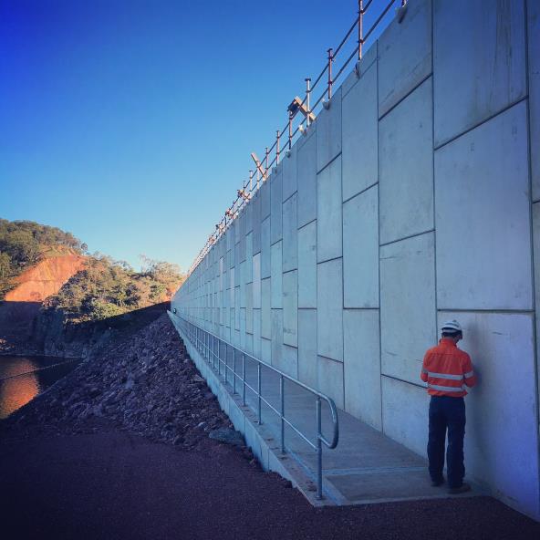
Photo 2 – Upstream Face of Completed RE Wall at Midpoint
-
Crest Works
Prior to my departure the crest works were well under way. Upon completion, the crest was to be used as a service road and so comprise of a bitumen sealed road with combined guard rail/ handrail on the downstream face. On the upstream face, the original 1.7m high pre-cast concrete parapets (or ‘L” panels) were to be installed.
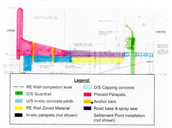
Fig 1 – Typical Crest Section
-
Vibrating Screed Rail
To support the precast “L” units, a 500m concrete plinth (6m x bays) was required. As access was difficult due to the close proximity to the edge of the RE Wall it was proposed that a steel support frame was designed to support the vibrating screed.
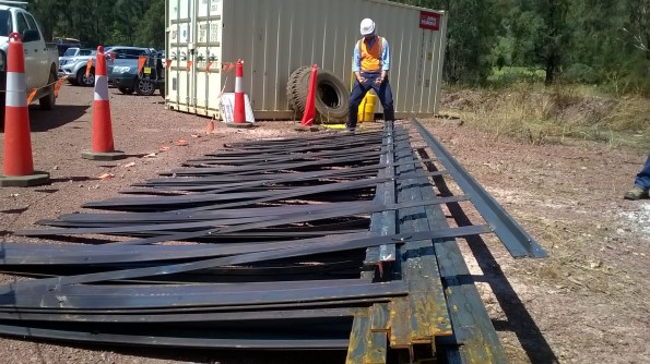
Photo 3 – SPE Having a Moment after Stubbing his Shin on my Screed Rails

Fig 2 – Typical Plinth Section Detail
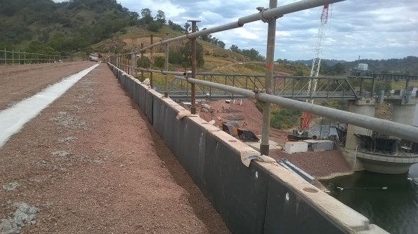
Photo 3 – Proposed Plinth Location
For simplicity, cost saving and time the steel rail concept was pursued. I assisted in the design, procurement and installation of the simple vibrating screed rail. Following review by the SPE and PM the proposal was accepted. Designs were produced and placed to tender across local steel fabricators. Essentially, it was designed to perform as a guide upon which a vibrating screed could be employed whilst also enabling the construction of circular voids within the fibrecrete slab (to allow subsequent HDG steel dowel placement). Geometrically, the simple steel frame was a perfect fit, however the structure was not without fault. The slender steel strips sagged greater than predicted. The strips were simply required to align white PvC conduits vertically, (allowing a circular voids to be created). To counter the bending, the 5mm steel strip could have been either increased in depth in order to reduce the slenderness or even reinforced with an additional steel strip along the axis. Unfortunately, rotating the strips 90 degrees was not an option due to the functional requirement.


-
Fibre Crete

Photo 4 – Example of Fibre Reinforced Concrete
As part of the crest completion works for the Chaffey Dam Augmentation and Safety Upgrade(CDASU) a 500m, concrete plinth (83 x 6m bays) was required to support precast concrete “L” panels on the upstream face of the dam. Due to the unusual geometry of the plinth (see Fig 2), the reinforcement was not straight forward. It was to comprise of 3 individual sections of steel due to limitations in the bending of the steel and logistical constraints. I therefore conducted a comparison between the use of a typical reinforced concrete slab using rebar and Steelfix (Hanson ready-mix fibrecrete). My research concluded that whilst the fibre reinforced concrete will reduce the effects of plastic shrinkage and a negligible increase in the materials tensile strength, it typically should not be considered as an alternative to well placed concrete and reinforcement within structural concrete fibre-crete.
However, for application in question and the relatively low loadings, fibrecrete was deemed suitable. In addition to the structural properties, it was assessed to to better value for money as construction time was significantly reduced and crucially, it did not required the high logistical costs associated with several tonnes of pre-bent steel reinforcement.
-
Countering the Effects of Differential Settlement
The deliberate variation in RLs between the surface of the crest at the centre and the dam and the abutments was approximately 250mm upon completion. The raised central portion was designed to allow for the differential settlement expected. As a clay core embankment dam is constructed, the partially saturated soil is compacted and consolidates as the water is expelled. This results in a reduction of volume of the soil mass.
As Chaffey Dam is constructed upon a rock foundation, it is the profile between abutments that will initiate the differential settlement. By this, I mean that the geometry of the void between the two embankments will result in a varied reduction in volume of clay core as you move across the dam (see figures below).
It is the differential settlement that has the potential to initiate lateral cracks within clay core of the embankment dam due to the tension that will develop in the dam crest where the foundation profile differs. At such points where a significant settlement differential exists, hydraulic fractures may result due to the low stress zones created along the surfaces (see fig below). Consequently, uncontrolled water flow may occur between the upstream to downstream of the structure…not ideal in a dam. Fortunately, most embankment dams experience 80 – 90% of the total settlement during the construction. Consequently, the stresses established in the construction phase assist to control the likelihood of low stress zones and cracking.

Differential Settlement initiated by Dam Profile

Differential Settlement initiated by foundation material
-
Leaving Chaffey
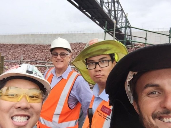
Photo 5 – “Special” Engineers at Chaffey

Photo 6 – Placement of the Final RE Wall Panel
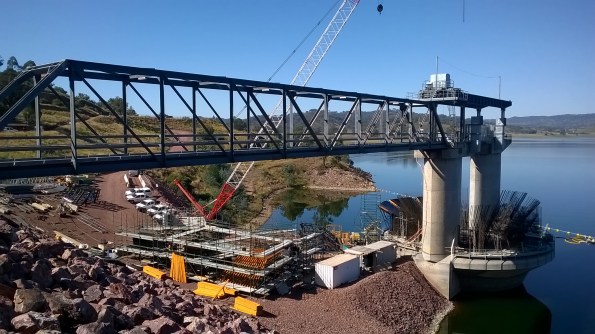
Photo 7 – MGS Construction Feb 2016
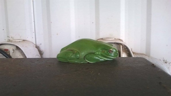
Photo 8 – Definitely NOT the Boolarong Frog that Delayed the Project by 5 years…
-
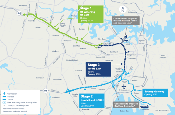
PHASE 3 – WestConnex M4 East Project
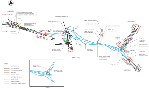
For my Phase 3 placement I am working on the WestConnex M4 East Project in Sydney. It is being designed and constructed by the CPB Samsung John Holland Joint Venture (CSJH JV). The M4 East Project will comprise of two new, three lane carriageways of which 5.5km runs below the city. Several access sites are to be installed along the 5.5km stretch to allow concurrency of works, enabling the removal of earth at multiple points. As such numerous cut and cover structures are to be installed.
My Role – Temporary Works Design Coordinator/ Designer
The schedule for my phase 3 attachment is broken down into three periods. Initially, I will be employed as the Temporary Works Design (TWD) Coordinator before working within a civil design team (AEH), a structural design team and finally a geotechnical design team (PSM). For the TWD Coordination role, my key duties are listed below but essentially the position will offer exposure to project-wide activities, enabling an insight into a broad variety of design packages, the overall design process and interaction with designers and PM’s leading each area of construction. Within each area, numerous works packages are raised which must go through a series of comprehensive design stages prior to release for construction. It is my responsibility to coordinate all aspects within each package, reviewing it at each stage before releasing for both internal and external review.
As I transition to purely conduct design I will focus upon one of the works package which I will have previously initiated as the TWD Coordinator. The proposed works package has been chosen due to the variety of engineering within. Essentially, it is a confined area of brown field site with varying levels which includes a haul road, a settlement pond, a portal frame acoustic shed containing a 7 x 7m vertical shaft and is in close proximity to housing and primary road. Initially, I will be analysing the portal frame and foundations before moving on to the shaft design with the geotechnical team.
Primary Responsibilities
Coordination
- Coordinate the preparation of temporary works design briefs (TWDB’s) with the Project Engineers and Project Managers for the tunnel and civil construction sites.
- Co-ordinate the temporary works design aspects of the traffic staging and surface construction zones.
- Assist in the preparation of Temporary Works Design Reports
- Maintain project wide Temporary Works Register (TWR)
- Brief Temporary Works design consultants on the design activities
- Participate in Safety in Design Reviews (SiDR) for the Permanent and Temporary Works
Design
- Develop a working knowledge of Structural Design Activities under supervision of the Senior Structural Engineer.
- Review design criteria and applicable standards.
- Analyse load cases and perform structural analysis using Microstran
- Perform designs for reinforced concrete and structural steel elements
- Review traffic stages and road geometry
- Review drainage and pavement designs
- Train in the use of Strand 7 and RAPT software
Life in Sydney!
Relocating from Tamworth was a pain.. Yet despite my initial reservations about leaving the country life for city, it is pretty awesome here. Cycling over the Harbour Bridge each morning makes up for any problems faced throughout the day.
Webbo Newspaper Article –Beers anyone ?…
Towards the end of my time at Chaffey Dam I had to deliver the quarterly Project Update Brief. The audience included all principle stakeholders, members of the local community, enviro, H&S, council members and the media.. As my PM kindly mentioned the fact that the original Chaffey Dam was built in 1976, also with the assistance of a British Army Officer, Capt RC Morgan, the busy Tamworth media jumped on the historic link and to my delight wrote this article…
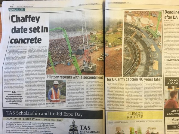
Chaffey Dam Media Article
