Archive
The calm before the storm…
On the 29th February I started work for Expanded Civil Engineering on the redevelopment of the Shell Centre. Expanded are a business group of Laing O’Rourke so all of the employees in the site office are Laing O’Rourke employees but are wearing the Expanded badge.
The project is a redevelopment of an existing site which was completed in 1962. The 1962 complex consisted of a high rise tower with a connecting 12 storey reinforced concrete low rise “horse shoe” shaped wing building. The existing structure is a concrete framed building above a podium with two levels of basement below. The site itself is adjacent to the major transport hub of London Waterloo. It is bounded by York Road to the east, Chicheley Street to the south, Jubilee Gardens to the west and the railway viaduct to the north. Running rail tunnels such as Bakerloo and Northern lines run beneath the site.
The redevelopment master plan has a mixture of commercial and residential buildings. The scheme retains the existing Shell Centre tower and site wide basement raft slab and walls with demolitions above and below ground, and with new construction comprising 2 commercial and 6 residential buildings with a two-storey basement in the north and a three-storey basement in the south of the site. It is worth noting that the residential buildings will have no social housing. The government requires up to a third of all new residential buildings to be affordable housing. However the owners have got round this by investing in a local school. It would appear there is far too much money to be made in this central location to waste it on social housing!
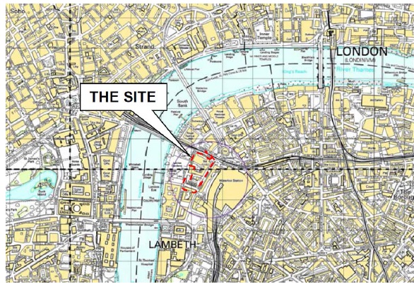
Site location
The proposed development will broadly comprise:
- Demolition of the existing site building, with the exception of the Shell Centre Tower
- Extension of the existing basement in the north east corner of the site and around the London Underground Ltd (LUL) ticket office
- Reconfiguration of the LUL ticket hall
- Construction of a new site-wide two-storey basement structure within the confines of the existing basement
- Construction of eight new mixed commercial / retail and residential buildings
Currently separate contractors, McGee, are completing the demolition of the existing buildings. They will demolish all the buildings down to their structural slab level. The site will therefore have multiple starting levels as shown below.
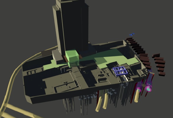
What the site should look like after the demolition works have been completed
The demolition works will be ongoing for a number of months and leads to a very congested site. However, Expanded (and more importantly the client) are keen to get working the moment there is enough space so construction will start in the southern end and follow the demolition works sequentially through the site.
 An example of how congested the site can be; the Expanded piling rig is in the background
There is also a growing concern with the construction plan changing last minute. McGee have proceeded with the demolition quicker than expected and the client therefore wants to accelerate the raft slab construction process. This would involve changing the whole sequence of slab pours and presents additional logistical challenges. The project engineer has so far not changed any plans as he is sure McGee will slow down soon.
An interesting factor has also occurred with a dispute between Expanded and McGee. It has been discovered that the guide wall for a secant pile wall has not been put in the right place by McGee (this has many in the Expanded office scratching their head as no one is sure as to why McGee, the demolition contractor, was tasked with casting a guide wall for Expanded). There is an ongoing dispute as to who is going to pay for it as the site was handed over, although no as-built survey was complete prior to hand over which is why no one has picked this up until just before the pile rig started piling. The dispute is ongoing…
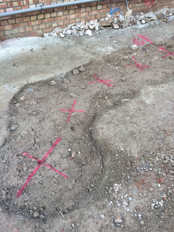
Red crosses show where the center of the piles should be compared to the guide wall
Currently we are in ‘the calm before the storm’; we will not be starting work on the basement raft slab until later this month and there is only minor ground works ongoing for the time being. In the mean time there is a lot of planning and work going on as most of the method statements for the works are yet to be written. This is quite frustrating for me as I find myself (much like phase 1!) writing method statements for processes I have only ever seen on paper. As a result I have to ask for guidance every half an hour! However I will be getting plenty of time on site in about 2 weeks for the foreseeable future.
In other news if anyone on the patch in Kingston fancies a game of squash, Jonny and I play at 1930 on a Wednesday night.
100 Bishopsgate – Understanding The Project
Project Background
On the 23 Feb 16 I started work with Brookfield Multiplex (BM) Construction Europe Ltd on the 100 Bishopsgate Project in central London. The completed project aims to provide approximately 950,000 Sq ft of high quality office and retail accommodation across two buildings, as well as a newly created half-acre public square. In general terms, the project has been broken down into three clear components; the Tower is a 40 story commercial office building which is designed to provide 32 office floors of highly efficient column-free accommodation, each measuring approximately 20,000 ft2. The Podium, which connects into the tower, offers five podium floors of 44,000 square ft each. Two basement levels under both of these structures provides room for services and car parking. 15 St Helens Place is designed as a 7 story steel frame and concrete slab structure which will be tied in to an existing retained stone facade and will feature a restaurant opening onto a public plaza and five office floors of 8,000 ft2 each. The project value is in the region of £460 Million and is scheduled to run for another 3 years.

Fig 1.1 – Plan view of 100 Bishopsgate Project as at 0900 01/03/16
Structural Design
In my first few days the site engineer who was also involved in the full design process of this building kept saying the same two things to me, both of which will be familiar to PET (C) students after phase 1. These were 1) ‘It’s all about stiffness. Stiffness is everything’ and 2) ‘Follow the load path, it’s as simple as that’. I’m not convinced it’s quite that easy, but based on his advice and a vague memory of our lecturers saying something similar in class I thought it wise to spend the first week trying to increase my understanding of the way in which each structural element has been designed to behave, both in the short term temporary condition and in the long term permanent state. In the most basic description I can muster, this is as far as I have got:
Below ground level, two basement floor walls are supported laterally, in the temporary and permanent state, by concrete slabs (GL, BL1 and BL2) acting as permanent propping between a perimeter secant pile wall. Vertically, these slabs are supported by shear connections to steel plunge columns and additional reinforced concrete columns.
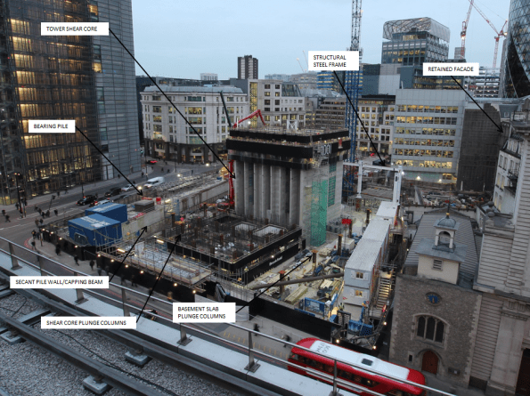
Fig 1.2 – Shear core progress imagery as at 1600 01/03/16
The Tower – Shear Core
Tower 1, as you would expect, is being constructed from a glass clad steel frame and composite concrete deck structure connected to a large central concrete shear core. This shear core, in the permanent state, is designed to carry roughly half of the Towers self-weight vertical load. It also transfers all of the high lateral wind loads (Max load of 32 MN in one pile) to ground through a series of very large reinforced concrete piles (Up to 1800mm dia) positioned directly under the core pile cap. They are therefore designed for the compressive and tensile forces resulting from combinations of self-weight and various wind loading conditions.
The Tower – Steel Frame
In addition to the shear core, the structural steel frame transfers self-weight load through large steel plunge columns located outside the shear core footprint or directly into large concrete piles outside the secant pile perimeter. The plunge columns have been cast into large diameter concrete piles (Up to 2400mm) that run to a depth of approximately 60m below ground level. This plunge column and pile system is designed to carry approximately half of the vertical load of the steel frame tower structure (Max load of 45.4 MN in each column), with the other half transferred down the shear core itself. Though the steel frame and plunge pile system provides additional lateral stability to the concrete core as it increases in height, in both the short term and long term condition all lateral wind loads are designed to be transferred through the core pile cap only.
In certain positions the design uses raked external columns that rise to a height of four floors. In the permanent state the load transferred from the self-weight of the completed tower induces a lateral, outward stress at the base of this column. In order to counteract this stress a large beam at ground floor level has been designed to resist these high temsile loads. The architects design (of course it does!) limits the size of the structural beam available, as a result specialist high tensile steel Gewi Bars have been selected to increase the tensile capacity of the concrete beam without increasing the amount of reinforcement bar required. With a quick google search I found 50mm Gewi Bars that can provide a yield capacity the region of 1MN each. There are 12 bars designed into the concrete beam and as a result are clearly critical beams behaviour in the permanent condition. At the moment there is an issue with resourcing these bars which has the potential to delay the critical path of this project by 7 weeks. This site runs at approximately £300k each week so the prospect of such a delay has got the Project Manager reasonably upset. I’ll cover this issue and my opinion on the project teams inital approach to mitigation in a more detailed subsequent blog.
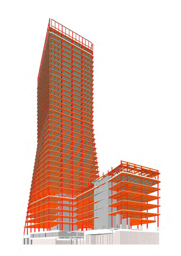
Fig 1.3 – Structural Frame Design
Podium and 15 St Helens Place
The Podium structure contains two smaller concrete shear cores surrounded by the same steel framed system used on the Tower. Over on the 15 St Helens site, a further two concrete shear cores will also be surrounded by a new steel frame and composite concrete deck structure. This new building will tie into an existing stone façade which must be retained in accordance with local conservation regulations. Currently this façade is restrained by a temporary steel frame structure on the front face. Other than self-load, this stone facade will not carry any additional vertical or lateral load imposed by the new steel frame structure emplaced behind it.
The Tower Load Path
The following diagram outlines my first attempt at a load path diagram for the tower component of the structure once complete. You’ll note I have indicated that the lower slabs are in compression from the total horizontal stress caused by the pore water pressure and effective stress behind the secant pile wall. The ground level slab on this diagram represents the position of the beam where the Gewi bars are required to provide increased tensile capacity.
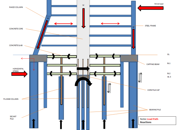
Fig 1.4 – Initial Load Path Analysis
Construction Method in General
The construction method of this project is a reasonably interesting aspect. Where resources allow, work on the three structures is being undertaken concurrently. In very general terms, my current understanding of the build sequence for the Tower component is as follows:
1. Secant Pile Wall and External Bearing Pile Installation
2. Perimeter Capping Beam
3. Internal bearing piles and plunge column installation
4. Excavation to BL1 (Exposing plunge columns)
5. Install Tower Crane 1
6. Commence Shear Core East Slip Form and St Helens Place foundation
8. Shear Core West and East Slip Form to level 6 – Install bracing steel work
9. Construct GL slab (Permanent Prop)
10. Emplace lower level steel frame (Minimum of five floors behind west core level)
11. Continue Shear Core to Level 10
12. Excavate to pile cap level
13. Construct 15 St Helens Place Steel Frame
14. Construct pile cap/BL2 slab (Permanent prop) and connect shear core concrete walls down to pile cap
15. Recommence core build beyond floor 10 and install BL2 concrete columns
16. Construct BL1 slab (permanent prop) and supporting columns
17. Install Tower Crane 2 and Tower Crane 3 (Both self-climbing cranes loaded onto the shear core)
18. Continue to Install structural steel frame for lower floors – Min of 5 floors between slip core and steel level
19. Install concrete decking – Min of 2 clear floors behind steel work
20. Install glass cladding on lower floors – Min of 8 floors below concrete decking
21. E&M fit out – Min of 4 floors behind façade cladding
22. Continue process to top out
This build programme involves top down and bottom up construction at the same time. It is designed to allow the structure on the lower levels to be completed, including fit out, as the building above it continues to rise to the point of top out.
At present state the site is excavated to BL1 and the concrete sub-contractor has started slip forming the west component of the main core. As soon as the Ground floor slab is in place (Gewi bar dependent) excavation of the basement will commence whilst the core continues to rise. Currently, the concrete core (East) up to level 6 is only supported vertically by a series of steel plunge columns that are cast below BL2 into large concrete piles. The bearing capacity of these steel plunge columns is designed for a maximum vertical load when the core is at floor 10, steel work is at floor 5 and concrete decking is at floor 1. Once the structure gets to this position these steel columns will be at the SLS design limit. Therefore construction of the lower basement concrete shear core and connection to the pile cap at BL3 is essential before further floors can be added beyond this point. As a result the progress of the concrete core upwards beyond level 10 (Critical path activity), is completely dependent on the top down construction of the basement levels.
As it stands there are a number of obvious issues which threaten delivery of the project along the critical path, I hope these will make good TMR submissions in the near future and I will try to update on how these are resolved and mitigated as the project team work through them.
CLOUD BREAKING DESIGN – AUSTRALIA 108
‘Australia 108 is a highly sculptural residential tower unlike any other in Australia. Its slender form is highlighted at the Cloud Residences levels by a golden star burst expression and then morphs into a curvaceous profile against the sky. The star burst which contains the resident facilities is inspired by the Commonwealth Star on the Australian flag and is an obvious celebration of the sense of community within the building’ – Fender Katsalidis Architects
This is what it looks like now….

This is what it will look like in 2020…

Project Overview: Australia 108 will be a 319m, 100 story residential building in Melbourne. When complete, it will be the tallest residential building by roof line in the Southern Hemisphere.
It is a design and build, fixed-sum contract to the value of $500m AUS. There is one basement level, one level of retail, 10 podium levels for car parking and the remaining floors to level 100 will be residential and amenities. To note the penthouse has sold for $25m AUS (equivalent to £12.5m) to give an indication of the quality and desirability of this build. Site preliminaries commenced in late May 15 and the foundations in Oct 15. The basement structure is due to finish in Sep 16 when construction of the superstructure should commence. If all goes to plan, the project should be reaching the soaring heights of level 10 by Christmas.
The 60 x 45m site is located on Southbank Boulevard approximately 300m from the Yarra River. It is situated on poor quality river deposits of soft silt and river gravels down to circa 35m where a medium – slightly weathered siltstone with good engineering properties is located. All high rise buildings in this area, bar one, have been constructed with podium levels above ground to house the car parks and to minimise the depth of excavation; this building is no different. There will be an excavation to a depth of one basement floor under the building footprint with a lift overrun under the core to a depth of two basement floors. Due to the available space on site, the majority of the excavation is being conducted by battering back the ground. Secant piling is being used for the core excavation and to protect a heritage façade from settlement. The groundwater was identified at a depth of 3.25m (RL -1.15m) during the site investigation but it is anticipated it could reach RL 0.0m from historical records.
The foundations are being constructed from replacement piles. The bored piles range in size from 2100mm to 1200mm dia. A polymer fluid has been used to support the bore holes until concrete pour. The remainder are CFA piles of either 900mm or 600mm dia. The only major issue encountered has been reduced boring rates due a narrow band of basalt in one corner of the site; this was factored into the programme and the subcontractors are on track to finish on time. Due to the poor engineering quality of the upper ground horizons, the piles rely heavily on base resistance and are designed with a socket length into the rock. This socket length is calculated to ensure that settlement of the pile is within tolerance under SLS loads, and is sufficient to resist any tensile force acting on the pile. Quality assurance is high to ensure that the design resistance is fully mobilised.
My Roles
1. Jet Grouting. I have arrived close to completion of the piling and the excavation commences next week. A geotechnical specialist, Menard Bachy, arrived on site today to do ground improvement works prior to the excavation. They are providing two functions: the first to place the soft piles in the secant walls by jet grouting columns between the hard piles; the second to jet grout a 1m thick water-reduction plug at the base of the core excavation. While this will not completely water proof the excavation it will significantly reduce the inflow of water to negligible levels. The ground slab will be poured on top of the grout plug. I have been tasked to work with the sub-contractors and provide the co-ordination, progress tracking and QA for this part of the project. It appears to be quite an interesting method having done some back ground reading on the subject, so I will maybe do a separate blog on the topic once I’ve spent a bit more time with the sub-contractors.
2. Starburst Co-ordinator. The starburst is the yellow clad star at levels 69-71. This will house plant at level 69 and residence amenities, including infinity pool, at levels 70 & 71. It will cantilever approximately 8m from the superstructure. At present this is a preliminary cost and has yet to be designed. A little headway has been made on the permanent structure by the Structural Engineers and a method statement has been drafted by a senior site manager. The two do not correlate and the initial work was only produced in order to submit a bid for the project. It is expected that the current proposal will radically change. I have been assigned the task of Starburst Co-ordinator, much to the relief of the other graduates. My role is to co-ordinate the ‘meeting of minds’ including those belonging to the structural engineers, steel consultants, concrete sub-contractor and the ‘brain’ from Multiplex’s Engineering Innovation Group (EIG) who is a world leader in high load structural connection design (James Murray-Parkes – google him). The aim is work out how this starburst is actually going to be built, produce the method statements, track progress and keep momentum on this part of the project and ultimately work with the commercial team to put the construction of it to tender. It will be a fantastic challenge although I will be long gone by the time construction actually commences on this part of the structure.


Particular notes I have found of interest from week one:
1. For a record breaking construction project, there are no engineers in the Multiplex team working on this project. The graduates are all project co-ordinators who all have construction management degrees. I will be working closely with the ground co-ordinator and the structure co-ordinator. They understand a lot about construction, obviously, but their technical knowledge is somewhat limited. I am waiting for a meeting with the structural engineer consultants next week to ask some questions which to date have gone unanswered.
2. The influence of the unions. The strength of the unions in Melbourne is staggering and they have significant influence over the execution of projects. If it hits 35 degree – work stops. If it rains (and I mean light rain) – work stops. If there is even a minor breach in H&S – the senior union representative can close the site (the project office remains open though so I don’t get an early knock off). It is a very interesting dynamic between the management team and the union reps, one which I will watch with interest.
I’ll keep you all posted 🙂
