100 Bishopsgate – Understanding The Project
Project Background
On the 23 Feb 16 I started work with Brookfield Multiplex (BM) Construction Europe Ltd on the 100 Bishopsgate Project in central London. The completed project aims to provide approximately 950,000 Sq ft of high quality office and retail accommodation across two buildings, as well as a newly created half-acre public square. In general terms, the project has been broken down into three clear components; the Tower is a 40 story commercial office building which is designed to provide 32 office floors of highly efficient column-free accommodation, each measuring approximately 20,000 ft2. The Podium, which connects into the tower, offers five podium floors of 44,000 square ft each. Two basement levels under both of these structures provides room for services and car parking. 15 St Helens Place is designed as a 7 story steel frame and concrete slab structure which will be tied in to an existing retained stone facade and will feature a restaurant opening onto a public plaza and five office floors of 8,000 ft2 each. The project value is in the region of £460 Million and is scheduled to run for another 3 years.

Fig 1.1 – Plan view of 100 Bishopsgate Project as at 0900 01/03/16
Structural Design
In my first few days the site engineer who was also involved in the full design process of this building kept saying the same two things to me, both of which will be familiar to PET (C) students after phase 1. These were 1) ‘It’s all about stiffness. Stiffness is everything’ and 2) ‘Follow the load path, it’s as simple as that’. I’m not convinced it’s quite that easy, but based on his advice and a vague memory of our lecturers saying something similar in class I thought it wise to spend the first week trying to increase my understanding of the way in which each structural element has been designed to behave, both in the short term temporary condition and in the long term permanent state. In the most basic description I can muster, this is as far as I have got:
Below ground level, two basement floor walls are supported laterally, in the temporary and permanent state, by concrete slabs (GL, BL1 and BL2) acting as permanent propping between a perimeter secant pile wall. Vertically, these slabs are supported by shear connections to steel plunge columns and additional reinforced concrete columns.
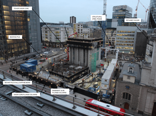
Fig 1.2 – Shear core progress imagery as at 1600 01/03/16
The Tower – Shear Core
Tower 1, as you would expect, is being constructed from a glass clad steel frame and composite concrete deck structure connected to a large central concrete shear core. This shear core, in the permanent state, is designed to carry roughly half of the Towers self-weight vertical load. It also transfers all of the high lateral wind loads (Max load of 32 MN in one pile) to ground through a series of very large reinforced concrete piles (Up to 1800mm dia) positioned directly under the core pile cap. They are therefore designed for the compressive and tensile forces resulting from combinations of self-weight and various wind loading conditions.
The Tower – Steel Frame
In addition to the shear core, the structural steel frame transfers self-weight load through large steel plunge columns located outside the shear core footprint or directly into large concrete piles outside the secant pile perimeter. The plunge columns have been cast into large diameter concrete piles (Up to 2400mm) that run to a depth of approximately 60m below ground level. This plunge column and pile system is designed to carry approximately half of the vertical load of the steel frame tower structure (Max load of 45.4 MN in each column), with the other half transferred down the shear core itself. Though the steel frame and plunge pile system provides additional lateral stability to the concrete core as it increases in height, in both the short term and long term condition all lateral wind loads are designed to be transferred through the core pile cap only.
In certain positions the design uses raked external columns that rise to a height of four floors. In the permanent state the load transferred from the self-weight of the completed tower induces a lateral, outward stress at the base of this column. In order to counteract this stress a large beam at ground floor level has been designed to resist these high temsile loads. The architects design (of course it does!) limits the size of the structural beam available, as a result specialist high tensile steel Gewi Bars have been selected to increase the tensile capacity of the concrete beam without increasing the amount of reinforcement bar required. With a quick google search I found 50mm Gewi Bars that can provide a yield capacity the region of 1MN each. There are 12 bars designed into the concrete beam and as a result are clearly critical beams behaviour in the permanent condition. At the moment there is an issue with resourcing these bars which has the potential to delay the critical path of this project by 7 weeks. This site runs at approximately £300k each week so the prospect of such a delay has got the Project Manager reasonably upset. I’ll cover this issue and my opinion on the project teams inital approach to mitigation in a more detailed subsequent blog.
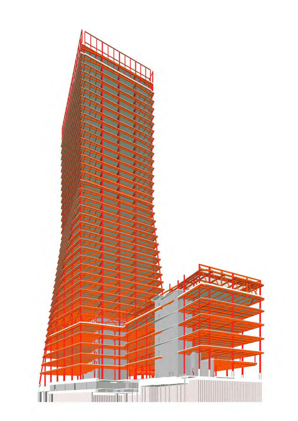
Fig 1.3 – Structural Frame Design
Podium and 15 St Helens Place
The Podium structure contains two smaller concrete shear cores surrounded by the same steel framed system used on the Tower. Over on the 15 St Helens site, a further two concrete shear cores will also be surrounded by a new steel frame and composite concrete deck structure. This new building will tie into an existing stone façade which must be retained in accordance with local conservation regulations. Currently this façade is restrained by a temporary steel frame structure on the front face. Other than self-load, this stone facade will not carry any additional vertical or lateral load imposed by the new steel frame structure emplaced behind it.
The Tower Load Path
The following diagram outlines my first attempt at a load path diagram for the tower component of the structure once complete. You’ll note I have indicated that the lower slabs are in compression from the total horizontal stress caused by the pore water pressure and effective stress behind the secant pile wall. The ground level slab on this diagram represents the position of the beam where the Gewi bars are required to provide increased tensile capacity.
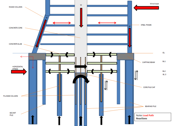
Fig 1.4 – Initial Load Path Analysis
Construction Method in General
The construction method of this project is a reasonably interesting aspect. Where resources allow, work on the three structures is being undertaken concurrently. In very general terms, my current understanding of the build sequence for the Tower component is as follows:
1. Secant Pile Wall and External Bearing Pile Installation
2. Perimeter Capping Beam
3. Internal bearing piles and plunge column installation
4. Excavation to BL1 (Exposing plunge columns)
5. Install Tower Crane 1
6. Commence Shear Core East Slip Form and St Helens Place foundation
8. Shear Core West and East Slip Form to level 6 – Install bracing steel work
9. Construct GL slab (Permanent Prop)
10. Emplace lower level steel frame (Minimum of five floors behind west core level)
11. Continue Shear Core to Level 10
12. Excavate to pile cap level
13. Construct 15 St Helens Place Steel Frame
14. Construct pile cap/BL2 slab (Permanent prop) and connect shear core concrete walls down to pile cap
15. Recommence core build beyond floor 10 and install BL2 concrete columns
16. Construct BL1 slab (permanent prop) and supporting columns
17. Install Tower Crane 2 and Tower Crane 3 (Both self-climbing cranes loaded onto the shear core)
18. Continue to Install structural steel frame for lower floors – Min of 5 floors between slip core and steel level
19. Install concrete decking – Min of 2 clear floors behind steel work
20. Install glass cladding on lower floors – Min of 8 floors below concrete decking
21. E&M fit out – Min of 4 floors behind façade cladding
22. Continue process to top out
This build programme involves top down and bottom up construction at the same time. It is designed to allow the structure on the lower levels to be completed, including fit out, as the building above it continues to rise to the point of top out.
At present state the site is excavated to BL1 and the concrete sub-contractor has started slip forming the west component of the main core. As soon as the Ground floor slab is in place (Gewi bar dependent) excavation of the basement will commence whilst the core continues to rise. Currently, the concrete core (East) up to level 6 is only supported vertically by a series of steel plunge columns that are cast below BL2 into large concrete piles. The bearing capacity of these steel plunge columns is designed for a maximum vertical load when the core is at floor 10, steel work is at floor 5 and concrete decking is at floor 1. Once the structure gets to this position these steel columns will be at the SLS design limit. Therefore construction of the lower basement concrete shear core and connection to the pile cap at BL3 is essential before further floors can be added beyond this point. As a result the progress of the concrete core upwards beyond level 10 (Critical path activity), is completely dependent on the top down construction of the basement levels.
As it stands there are a number of obvious issues which threaten delivery of the project along the critical path, I hope these will make good TMR submissions in the near future and I will try to update on how these are resolved and mitigated as the project team work through them.

Tom
An excellent start – well done. Things certainly sound ‘interesting’ from the off.
PS do not forget your ICE 3144.
Kind Regards
Neil
This is a very good blog
The description of how the structure works is clear.
The major problem is the tension that needs to be developed in the GL slab between the toe of the raking colums and the core to tie the toe of the column in
Two observations:
a) the full tensile performance is not necessary unitl a good deal of the superstructure is completed
b) I wonder whether the tensile load designed as necessary in the GL slab was offset by the pre-compression as the slab is being used to act as a compressive strut for the basement walls?
In other words the basement compression comes on before the tensile performance is necessary so give some ‘free’ tensile performance and the full tensile performace is necessary far later – I am sure there is a solution here that would ameliorate the need for GEWI bars right now.
In any event a nice TMR is the brewing me thinks!
Tom,
I echo the sentiment of my colleagues – very good first post. I don’t understand why anyone, other than a steel designer, would introduce 50mm tensile bars into a slab that could simply be prestressed thereby seeing reduced prestress rather than increased tension as load goes on. Has this not been considered? If there are issues early on in construction the tendons could be post tensioed at the approriate point in time no ducking furries?!
With in situ floors and slip forming cores you should anticipate a course site visit…