Archive
LSHTM Condensate Recovery Analysis
LSHTM Steam System:
My involvement in the London School of Hygiene and Tropical Medicine (LSHTM) steam replacement continues. I’d hoped that the design would be complete by now and that I’d be moving on to something else but there’s been a slight question 4 moment. But I’ll come onto that in another blog.
Intro
As previously mentioned steam systems generally consist of steam mains (flow) and condensate (return) pipes. Condensate is transferred from the steam main to the condensate pipework by means of a steam trapping station. The system we are putting in is mainly to supply autoclaves (sterlisers), but is also a backup supply for a heat exchanger if the normal LTHW boiler falls over. When the steam gets to the autoclaves it will transfer to condensate like in any load, except that in autoclaves the condensate is then contaminated and cannot be returned to the steam generator. This means that the only condensate available for recovery is from losses in pipework during running and warm up and cool down. Bryden Wood’s proposal which won them the job was to generate steam at high level (fourth floor), collect condensate and send it under gravity to low level (basement) and pump condensate back up to the generators in a separate pipe.
I’ve calculated that on a normal day LSHTM will use 10m3 of water for steam, 3% of this usage is due to running losses and is potentially recoverable the rest goes down the drain via autoclaves. What is less clear is what should be done with the condensate that is recoverable. Was the original Bryden Wood proposal correct? I was originally told that we were recovering condensate as it is best practice and the most cost effective method. This blog will cover some COA analysis on 3 possible options to deal with the condensate being recovered:
COA1:
Stick to the plan as described in the Bryden Wood proposal. This will require the installation of a condensate recovery unit in the basement. This is basically a tank vented to atmosphere which collects condensate that falls under gravity and allows it be pumped back up the building by means of an electrical pump. The tank is vented to atmosphere to minimise the possibility of cavitation occurring on the pump due to a sudden pressure drop in a liquid at high temperature. This plan is in line with common thinking associated with steam operation: always recover condensate. This is because by reusing condensate you don’t have to heat feed water up from 10 oC so energy is saved; you don’t have to pay for more water and also to treat more water. Although as highlighted above the system being put in place will only have 3% of the total steam used available for recovery. This leads to a saving of £1.81 a day by having a condensate recovery unit or a payback period of 7.5 to 17 years, depending on the type of condensate recovery unit, not including installation and running costs. Doesn’t seem worth it. However this does not factor in the back up heat exchanger. Although never / rarely used, if this system were to be used it would generated up to 600kg / hour of condensate. This then starts to have a more significant cost saving of £3.62 per hour. Although this saving is unlikely to impact the payback period as the heat exchanger would only be required to cover outages which would unlikely be more than a couple of days a year on average if at all. It still doesn’t seem cost effective to utilise. However one of the environmental requirements of utilising steam is that any water discharged to the foul drain cannot be greater than 43 oC. Condensate at atmospheric pressure will be just below 100 oC. If a condensate recovery unit were not used then another means of getting condensate away from the heat exchanger would be required or to cool it before going into the drain.
Strength:
- Provides a solution that is in line with industry practice.
- Allows system to drain fully on start-up and cool down avoiding water hammer.
- Does not result in hot condensate being discharged into the drain.
Weakness:
- Returning condensate does not offer a huge cost saving.
- A condensate recovery unit will take up space in the basement.
- An additional piece of equipment is required which will require maintenance.
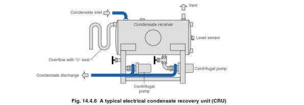
Typical condensate recovery unit.
COA2:
Rather than collecting condensate via gravity just put it into the existing drainage near to the steam traps where it is collected. This drainage is designed to deal with hot liquid from the autoclaves and should therefore be cooled by the time it gets to the foul drain. This goes against best practice, but is based on the fact that the assumption there is a cost saving of recovering condensate is flawed in this situation. Potential condensate from the heat exchanger would still need to be dealt with but this could be achieved by using a self-contained pump trapping station which would fit on the existing heat exchanger skid and utilise steam power to push condensate back up to high level. Unfortunately getting to the existing drains from the steam traps is easier said than done and will create a huge amount of disruption not to mention the requirements to install vent lines everywhere; when condensate that was at 6 bar g passes to atmosphere a large portion of it will want to flash to steam, therefore vent lines would be required to avoid pushing steam into the drain. Therefore due to installation issues this option was not considered any further.
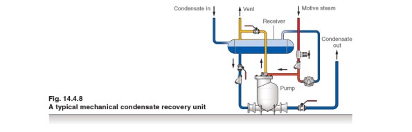
Typical steam powered condensate pump.
COA3:
Same as COA2 but rather than putting the condensate from the traps to drain utilise the pressure difference across a steam trap (6 bar on steam side, atmosphere on condensate side) to push the steam back up the building to the steam generators. The lowest steam trap is 16 m below the generators, so allowing for backpressure and friction losses there should be a net pressure of 4 bar to push the condensate back to the generators. However when the system is turned off and cools down the pressure across the traps will drop until there is not a net pressure difference. At this point condensate will not be recovered and will fall back to the non-return valves on the traps. When the system is brought back on the condensate in the pipes will rattle back to the steam plant potentially causing noise and damage as it goes.
Strength:
- Recovers condensate in line with industry practice.
- Minimises the amount of equipment in the basement.
- No running costs associated with an electrical pump.
Weakness / Threat:
- Water hammer and noise on start up.
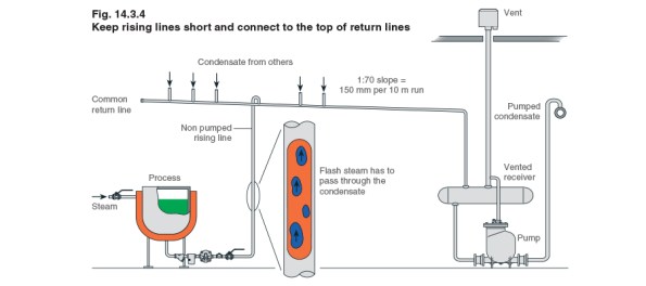
The left hand side of this figure shows a steam trap at the bottom of a process being utilised to lift condensate up to a common return line.
For this reason I’ve decided to stick with the original plan. This led me to question whether the exercise had been worthwhile. I believe it was. Although I’m not changing the scheme it’s always good to question what is put in front of you rather than accepting it blindly. Secondly I believe the reasons that I have come up with for sticking to COA1 are slightly different to the reasons why it was selected in the first place: I am selecting it based on it being a solution that minimises problems with respect to installation and running, whilst the original logic was that it was the most cost effective solution.
