Temporary v Permanent…
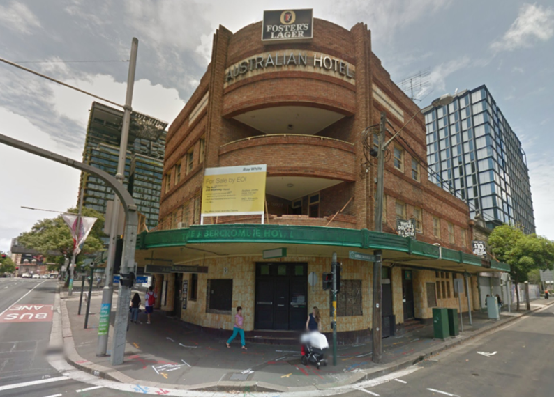
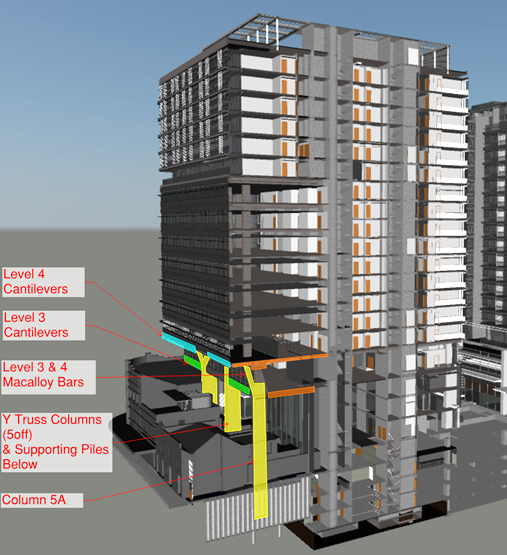
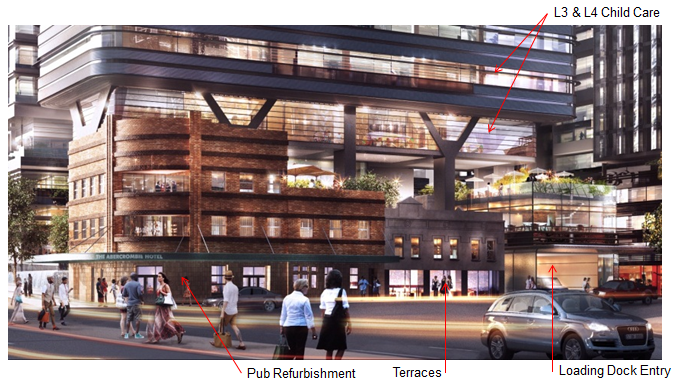
Situation… So I am responsible for the section of the structure which will envelop the heritage building in the image above. In the permanent state, the structure will surround the heritage site as shown in the two images below…
Issue… Whilst the beam, which allows level 3 of the structure to cantilever over the heritage building, clears the roof in the permanent state, it fouls it in the temporary. The beam has to be poured in two stages due to its depth. In order to achieve the required strength between pours, the depth has to increase from that required in the permanent state. This causes the beam to foul the roof of the heritage building… Ah!
Options…
- Accept the collateral damage and remove a section of the parapet wall to allow for the beam.
- Prop the beam in the temporary state, allowing the beam depth to be reduced to that required in the permanent condition, thus avoiding a clash with the roof. However, to accommodate these props the floor boards and roof tiles will need to be removed and ceilings penetrated. The props will have to be strategically positioned to avoid joists and rafters. Once the beam has reached its required strength, the props can be removed, floor boards and tiles replaced and ceilings patched.
The heritage authority aren’t exactly happy with either of these options but think option 1 is the lesser of the evils. A structural survey of the heritage building is soon to take place and if I were a betting man, I anticipate huge aspects of the heritage building will be condemned. If the floors, ceilings and roof need replacing, option 2 may take the lead.
I will keep you abreast of the situation once a decision is made.

So the cantilevering beams are the deep edge beams ( blue L4 and green L3) running away from us in the 3D model? They are (both?) cranked edges cantilevering to the corner of the building approximately above the curved edge of the heritage ‘pile’?
From the artist’s impression we can see that the ‘Y’ beams operate at L4 and that the L3 slab appears to be set back form the cantilevered L4 edge
I wonder why the L3 slab edge beam is so deep – it looks like there could be a drop tie to pick it up at the corner edge form the L4 Y column above it
In any event I can’t get my head around the note about temporary and permanent state. Is it that the falsework to cast the edge snags the roof?…..in which case I still refer to possibility of dropping a falsework support form L4 and holding the L3 edge completion until L4 is in place?
Correct, L3 doesn’t cantilever as far as L4. The beam I am referring to runs parallel to the lower of the two orange beams in the 3D model. There is a ‘Y’ column on the extreme left of the artist’s impression, which can’t be seen in the 3D model, the beam runs from the top of the vertical section of that ‘Y’ column, just at the point the column splits to form the ‘Y’. It is the false and formwork to this beam which clips the parapet wall running around the heritage building. If it could be ‘wished into place’, there would be no issue. If we can support the beam through alternate means (propping) then the beam depth can be reduced to that required in the permanent state and the clash with the roof is avoided. Clearly this comes at the expense of penetrating the heritage building with props. Discussions are ongoing with the formwork sub-contractor to find a solution which works for all parties.
Andy,
I can’t see why need to touch the ‘heritage’ heap. Think bailey bridge launching nose and extend your false work to give a simply supported structure spanning over the heap that can be removed when the cantilever has the strength to self support. simples! Failing that cantilever out your false work above the desired beam and hang the formwork from it.
Level 3 is clearly intended to look like a light weight floor tucked in beneath the heavier structure over so I would anticipate a desire for minimum structural depth. What are the proposed materials? RC frame and slab, prestressed deck units, prestressed flat slab? I can see a ;large corner column on the nearest coner in your ‘model’ and guess that is absent on the front corner but it could exist as a hanger between level 3 and 4? Why the Macalloy bars at level 3 and 4 on the ‘rear’ corner?
It would be good if you can wade into the false work issue. I suggest you knock up a couple of hand sketched models to show the issue more clearly. It might help you find a solution and, because you’ll be there to see implementation, this will yield CPR gold on the innovative technical solution and evaluation front. Or you could let it run as is…
Looks like a sexy building with lots of potential for nice structural tricks to work around robustness/seismic challenges – very jealous of the structural engineers on this one.