Ground Improvement through Jet Grouting
Jet Grouting
Jet grouting is a construction process which employs a high kinetic energy jet of water to break down a soil formation into suspended particles and mixes the in-situ soil with cement grout. This process of hydrodynamic erosion of the soil and mixing forms a soil-cement mix which has improved properties. There are three distinct phases to the process (see Figure 1):
- Breakdown of soil formation using high-pressure jet. A borehole (90-150mm) is drilled to depth and fluid is pumped at a pressure >450bar to the base of the drilling rods to breakdown the soil formation.
- Introduction of grout. The rods are rotated slowly as they are extracted from the borehole and cement is pumped from the base of the rods simultaneously. This creates a column of soil-cement mix, evenly distributed through the treated volume. This phase of the process uses a computer to control to extraction speed, rotation, grout pressure and grout flow.
- Displacing of excess material. All excess soil-cement mix exits freely to the top of the borehole and removed. The pressure is stopped 500mm below ground level.

Figure 1 Jet Grouting Technique
Requirement at Australia 108
The scope of works for the Australia 108 project was to provide a jet grout plug from RL -7.0m to RL -8.0m to act as a strut against the core retaining wall and reduce estimated deflection during excavation. This would enable a 6m deep excavation from RL -1.0m to RL -7.0m without the requirement for walers and struts. It would also serve as a plug to reduce water ingress into the excavation. In total 106 jet grout plugs were placed varying in diameter from 1.4m to 2.2m, (see Figure 2). The ground conditions from RL 0m to RL – 17.0m is Coode Island Silt which is soft to very soft silty clay with high plasticity. The GWL sits at RL 0m. Menard Bachy secured the contract for these works.

Figure 2 Jet Grout Column Arrangement
Trial Works
The strength of the grout mix will be tested to confirm that 2MPa has been achieved at 28 days based on cubes sampled daily from the spoil return. It is possible to core the jet grout plug in situ and test but it is preferrable not to. Instead trial works were done prior to production of the core plug. The aim of the trial was to allow commissioning of the grout batching, pumping and drilling equipment and to ensure that the columns are consistent with the design assumptions.
Six jet grout columns were arranged as per Figure 3 to achieve overlaps of 400mm between 1.4m and 2.2m columns, and overlaps of 300mm between 2.0m and 2.2m columns. The trial columns were installed at the same depth approximately 10m away from the permanent location. The overlaps were cored and visually inspected to check for integrity prior to commencing the permanent works (photo of core sample at Figure 4). It was assessed that close to 100% of the Coode Island Silt had been replaced by grout and that the overlaps have been achieved.

Figure 3 Trial Column Arrangement
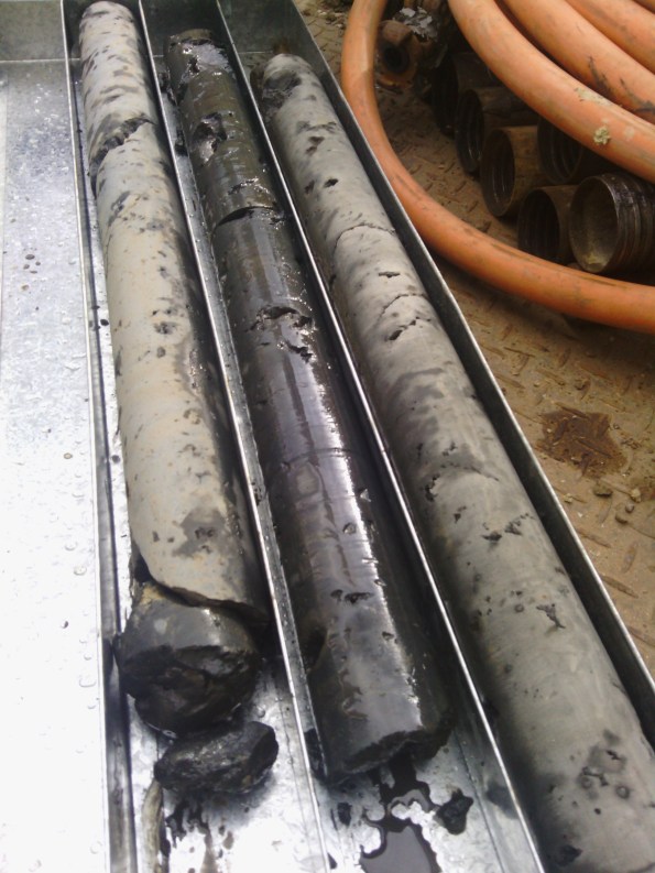
Figure 4 Photo of Trial Column Cores
Risks
The greatest risks with this method are as follows:
- Not achieving required depth.
- Not achieving column depth.
- Incorrect drill location resulting in insufficient overlap between columns.
- Damage to near-by structures and uplift due to the high pressure and flow rate.
To mitigate these risks, the jet grouters rely heavily on computer control and monitoring. The operators are given design parameters from the engineers and they ensure the equipment is calibrated and they adhere to these parameters; they provide a drilling record for every column as part of the QA process. They also drill approximately 100mm above and below the target depths to ensure there is a consistent band at the required depth. They also use GPS and surveyors to locate the boreholes pre drilling and provide an as built post drilling record. If a column is installed in the incorrect location or depth, the process can be repeated in the correct location as the pressure is sufficient to erode the soil-cement mix.
Method Statement and photographs
I have included below a simplified method statement to demonstrate the how the jet grout plug is installed prior to the core raft, as well as numerous photos so you can see how the actual construction process looks. In practice, it took a lot of co-ordination on site as the site set-up and trenches to remove the fluid spoil were a considerable laydown. Interestingly though, one thing I couldn’t capture well on photo was how much the ground bubbled due to the sub-surface pressures created by the process.


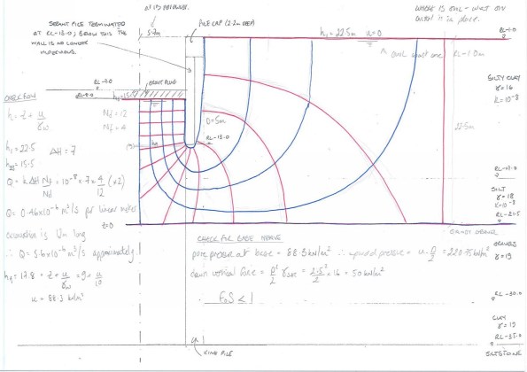
Flow Net

Flow Net Take 2

Thanks Jo,
Sketches and explanation exactly as required 🙂 even I can understand. I notice the photos seem to show reinforcement cages (3rd image in top row), is this a red herring? The ‘concrete’ is a very weak product at 2N/mm^2. You said ground water is at RL 0m which begs two questions: 1 How is the contamination of ground water being managed (yes I see the settlement tanks but that’s a bit late after it’s been mixed at depth, pushed around under pressure and swilled over the surface!). 2 is this lean mix blinding really going to stop the base of this excavation lifting/losing all strength?
Finally have you considered how this 14 m long slab/strut is working with fcu=2 and no tensile reinforcement but with an applied deviation force arising from self weight one way and ground water + base heave the other? What loads is it actually carrying? Looks a little like another very thin slab on another site recently described as a prop…
Jo, very interesting method of avoiding props. Although you have a 6m cantilever unsupported, what deflections are you expecting at the ground level? Do the massive (1.8m diameter) retaining wall piles seek to prevent much deflection (I assume that big for the permanent case)?
Just on levels, your sketch shows you are excavating from RL -1.0m, but GWL is at RL 0m – are you dewatering prior to the works? I assume you must be otherwise I think your slab would be buoyant when you excavate!
I thought, based on your levels, the plug is 1m thick (possibly a bit more due to method of construction) so a decent size, albeit not so strong.
Following on from Richards look at vertical forces from water and heave – I assume the subsequent raft on top produces sufficient vertical load to stop this being an issue? Did you check the lateral contribution from the retaining wall to prevent the plug moving up in the short term before the raft is cast?
In attempt to answer some of the questions above…
Richard:
1. The reinforcement cages have merely photo bombed the picture. We were still piling concurrent to the jet grouting and had no part to play in the process. Also the settlement tanks are for the bored piles. There was actually very little done with regard to ground contamination management. As shown in the photos, trenches were dug to contain the soil-cement spoil that was kicked out of the borehole. It was literally left in the trench overnight for the fines to settle, the fluid was then pumped off and discharged to trade waste through a filter and the remaining slop was simply dug out using the excavators and taken away as non-hazardous trade waste.
2. To understand the loading on the grout plug / strut I need to understand what is happening in the ground. The design subsurface profile is: Silty Clay (0 to -17m), Silt (-17 to -21.5m), Gravels (-21.5 to -30m), Clay (-30 to -35m) on top of the siltstone >-35m. I have attempted some flow nets to try and determine what the pressure is on the underside of the plug but I’m two versions down with John and still working on it 😐 (I’ve attached them to the original blog so if anyone else wishes to have a go and point me in a better direction, please feel free – were all here to learn!). As the core wall attempts to deflect in as the depth of the excavation drops, an axial compressive force on the plug / strut will be imposed The specifications of the plug is to achieve a compressive strength of 2MPa and tensile strength of 0.1MPa, therefore I would deduce that the grout is designed to work as a compressive strut, (could you say it is pre-stressed?) with a vertical deviator force which is almost negligible in comparison. Whether all this is sufficient to prevent base heave?……I’ll be better able to give an answer to that when I finally crack these flow nets and lateral earth calculations. The Geotechnical Engineers are not concerned about base heave at all.
Damo:
1. I suggested we asked for deflection tolerances for the core wall when I started to look at this problem and the GE’s anticipate less than 5-10mm deflection with the reg flag rising, stop digging, at 15mm.
2. There is no ground water management plan. I have asked a few people from the co-ordinators and the site manager who all do not seem concerned by water – ‘we’ll just drop a sump pump into the excavation if we need to’. I raised the point that the GWL was specified as RL 0m in the GDR yet we are bulk excavating and battering down to RL-1m prior to the deep excavation. I know the graduate engineer who works for the subcontractor has also asked the same question and was patted on the head very politely when he did. I am interested to see how it will pan out.
3. I haven’t done a lateral load calculation as yet because I am still trying to visualise how I would model it. The king piles – rightly said are designed so large for the permanent load – are socketed into the siltstone at > RL -35m where as the shorted secant piles go down 5m below the base of the grout plug. Would I model it as a simple fixed earth cantilever and see what forces are generated at the height of the plug (equal and opposite reaction etc), or would I use a free earth cantilever and represent the plug as a prop exerting an action on the wall. Rhetorical question – I’m still thinking this through for myself!
I know this hasn’t done too much to answer your questions. I have some rather large gaps in my knowledge (which I am trying to fill), what assumptions have been made concurrent to trying to remember what we’ve been taught and apply it. I would love to know how the Geotechnical engineers have modelled this to verify their computer modelling, assuming that is they have.
Jo, Thanks for your reply. I have had a second think.
Quick clarification – I assume the grout plug is as shown – i.e. a grid of connected plugs with gaps in?
Water – in the silty clay of low permeability (perhaps lower than 10-3m/s?), as soon as excavation starts the cohesive silty clay material becomes undrained. In the short term (for as long as it takes to excavate) it is likely to remain undrained. Therefore there might not be much need to deal with water. Any water (perhaps held in sand fissures) might need to be pumped out with a sump, but as it will take a while to flow through the silty clay as soon as the water is pumped out that will be it. Therefore, perhaps no need to dewater and probably not much water will be seen during excavation because of the pore pressure suction created during excavation.
I don’t think there will be much water coming through the grout plug grid in the short term and in the long term the blinding and raft (and actual structure) will act against water pressure build up. I wonder if the raft will be dowelled into the piled wall?
I think your flow nets assume drained conditions, or moving towards drained conditions – but is that likely in the ‘short’ time you will be at full dredge level?
Heave – the grout plug is 1m thick, so what if there is a bit of heave in short term? The plug moves up a bit – probably does not make any difference.
The grout ‘strut’. Using a highly conservative drained free earth analysis (assuming toe level of 7+5m, rather than full king pile depth) by hand (phi’ of 12), I get a prop force over a strut area (assuming the plug is actually a grid of struts and taking a strut area of 1.4m by 1m depth) of 1MPa (unfactored), so much less than the 2MPa stress capacity. So strut acts in compression at about half of the required stress, less when factors of safety applied but probably still well in. [That was pretty rough and ready, so might be out].
So in essence, plan sounds fine! As you say, time will tell.
Damo, I think you’ve massively helped me to get some clarity on this. I’ll have a go at the analysis as well and see i get the same ball park. Of note, the first tests are back and the grout has been achieving a strength of 5-6 MPa.