The Devil is in the Detail
Phase 3A must construct three large temporary bridges that provide access through our site – both for adjacent phase’s construction traffic and future residents. The 3D CAD model below provides an illustration. I have responsibility for bridge 1. The bridge section spans over 54m and it has two decks of 24m length at either end. It will be suspended 18m above formation level (when we eventually dig down to basement 3 level).
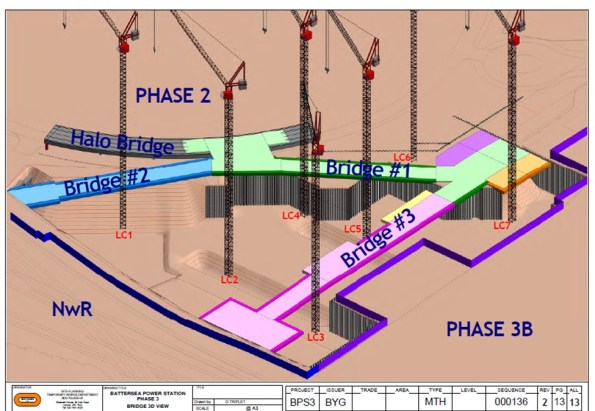 Temporary Bridge Structure – 3D CAD Model
The Problem
Bridge 1 must be in place to allow residential occupation of Phase 1 (Carillion’s site) in Q4 2016. As a result, the client’s driver is time. Unfortunately, the temporary bridges have been designed in isolation to the permanent structure and only considered on plan. As one can imagine this situation has created many clashes.
The Solution
The Devil is in the detail and the solution requires all the stakeholders input. De-confliction is the name of the game and the majority of my time has been spent in meetings trying to work through solutions. The greatest difficulty lies in the area of the temporary bridge deck supports. These ‘dolphins’ (the nomenclature on the drawings) consist of piled foundations with high level pile caps that support the bridge deck. The drawing below illustrates the initial design with uniform spacing (coinciding with the deck spans).
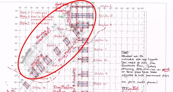 Bridge Supports – Initial Design (relatively uniform supports)
My task has been to knock heads together to come up with a mutually beneficial solution for all. I have convened meetings with the temporary bridge designers (McGee), the permanent structure designers (BuroHappold Engineering), the piling contractors (BBGE), the M&E designers (Chapman BDSP) and the construction sequencing team (Bouygues UK). The outcome of these painful liaison meetings can be seen below. One reason these meetings are so painful is because still no-one has signed a contract. Whilst not the most exciting Blog post the two photos represent a couple of weeks work and provide an idea of the small victories won. The next stage is to attempt to reduce the size of these temporary bridge supports…
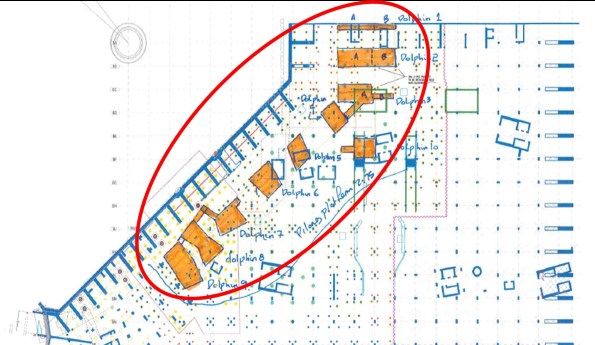 Bridge Supports – Post De-confliction (variable shaped supports)

That is quite a large temporary structure Rich! What material is the bridge likely to be constructed from? Is it a LSB type steel frame system? We have a very small temporary reinforced concrete bridge on our site; it’s going to be a right pain to strip out so hopefully you lot picked something more practical considering its dimensions.
Richard
A cheeky little problem with so many stakeholders. I assume that it is going to be
A Maybey bridge that can easily be erected and dismantled. Good luck. I would like to drop in on you when I visit Jonny
Kind regards
Neil
Neil, Tom
The bridge is a pre-fabricated steel deck design. Not a proprietary system… Although McGee have ‘modularised’ the design. The individual spans are either 15m or 18m and are a ‘standard’ (for road transport) 2.8m wide. The deck is a maximum of 1.5m deep and is the only piece of the design agreed. This allows it to be fabricated whilst we argue over the bridge supports.
Rich,
A dolphin derives from a marine term for the berthing piles used to moor against; they can be single piles but tend to be three or four pile groups with an elevated cap, fixed fenders and mooring cleats. Your bridge deck support platforms in original concept look much like these structures so I suspect someone that has either a marine engineering background or they sail!
I’m a little confused by the sequencing of all this. This bridge leads to the railway? You can’t get on or off to the sides other than at Halo Bridge (permanent). It is going into place before you dig out beneath and build the basement levels. When are the sheet piles going in? The route does not exist in the final configuration so it has been removed at some point and not replaced with an alternative route. How does this work? What is the trigger for closing this route and could it be brought forward or forced to slip back? Are the drawings showing you installing piles beneath the bridge adjacent to its support dolphins? All very bizarre! Probably something I’ll need to come up and have explained to me…
Rich
Dolphin terminology, I thought it best to spell it out – very conscious I am dealing with the M&E crowd on here…
With regard to the sequencing – I see how the 3D model is very confusing. I’ll try to explain.
Orientation to the 3D Model
Taking the Halo Bridge as North.
To the north is the Battersea Power Station building (4 chimneys, brick structure, iconic building)
All along the western side (NWR boundary) there is an access road which links in to Carillion’s site (Ph 1). On the model it is not shown for clarity.
On the eastern side (slightly to the right and behind tower crane 7 – LC7 on the CAD model) is the main site access. This is technically in Phase 4 site but construction is 2 or 3 years off – likewise not shown for clarity
Halo Bridge – Permanent structure presently being built by Skanska (Ph2). Imagine a giant Polo mint all the way around the original Battersea Power Station brick building and that gives you an idea. At present the polo mint will only be half complete (to the NW of our site). Not to the NE because of Skanska (Ph2) sequence of works.
So the temporary bridges provide access ACROSS our site
Sequencing
Presently there is an access road right through our site along the alignment of Bridge 3. We must maintain that access (not for us but for others (Ph 1 and 2)
The trigger to close the existing access and allow us to excavate our basement is that the temporary bridges must be in place.
The original methodology was in theory:
Bridge 1 – Residential Access
Bridges 2 and 3 Construction Access
However due to the delayed programme this is no longer the case.
Bridge 1 will be put in place first which will allow us to close the present access (along the alignment of bridge 3) and start excavating.
Site Boundary Piling – Concurrent… Sort of(!) some of the piles are already in place (by others).
Along the NWR boundary a secant pile wall and the remainder will be sheet piled (with a scenario frighteningly like Ex Cofferdam – no vibro driving, excessive pile length, push/pull rig, pre-auguring and jetting etc etc).
Permanent Pile Foundations – Concurrent.
Alternative Route/Trigger to stop access right through out site – completion of the Halo Bridge polo mint right around Skanska’s site – years away (Skanska are nearly a year behind schedule)
Piling beneath the bridge – Yep(!) and the detail is still to be clarified, in fact the pile design is still to be completed
Probably a poor description but hopefully of some assistance.
It will be a fascinating visit toward the end of the year – from a sequencing and planning perspective.
Thanks Richard. This will be interesting 🙂