More heritage complications…
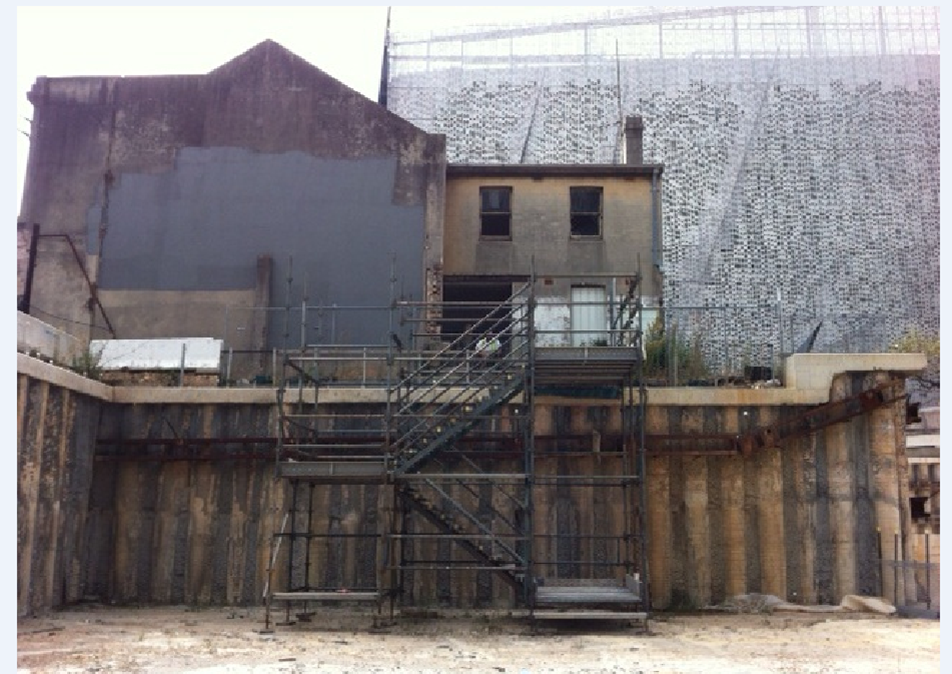
Consistent with my other blogs, this one also focuses on a heritage issue. Our structural design consultants have deemed the heritage building so unstable that much of it needs remediation before adjacent works can continue. Whilst there are many areas which require attention, this blog will focus on ‘The Southern Wall’. An elevation of the Southern Wall is shown in Figure 1. It is the wall without windows, half painted grey and it is a miracle the thing is still standing.
Figure 1.
Several methods of reinstating the structural integrity of the building have been investigated but due to the time it takes to gain permission to do almost anything inside a heritage building, the level of internal instability between floors, contractual complexities and more – a temporary external fix has been selected. The solution involves three levels of walers being attached to the wall and then braced by a series of props. The solution is illustrated in Figure 2 and Figure 3.
Figure 2.
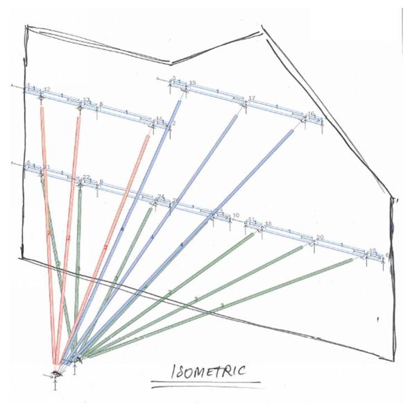
Figure 3.
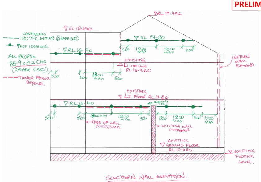
This solution minimises the impact on the programme and allows works in the vicinity to continue, largely uninterrupted. The lower most waler is supported by the green props which all converge on to a single brace plate (BP1). The brace plat is bolted to the existing capping beam, but has had to be drilled to slot over the starter bars. The other two walers are braced by two separate groups of props, all of which converge to a second, separate brace plate (BP2). See Figure 4 for detail. Connection details are illustrated in Figure 5.
Figure 4.
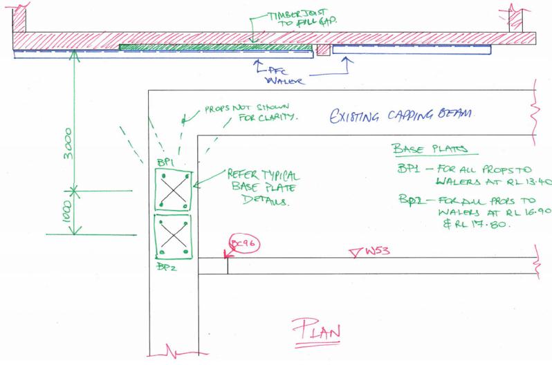
Figure 5.

Not only does the steel provide support in elevation, they also prevent the road side elevation from falling into the adjacent street. It is difficult, but possible to see in Figure 1 that the western most 1.8m of the building (the left hand side) is almost entirely separate from the rest of the structure. Existing internal braces go some way to remediate this problem, but the proposed solution will help to prevent the matter from getting worse.
The long term solution is expected to be in the form of timber frames which will be sandwiched between the ceilings and floors of the building. Due to the issues highlighted at the start of this blog, this long term solution will be tackled in the distant future. This temporary solution is due to be constructed this week, I will post photos once complete.

Interesting! Propping systems are usually symmetrical. What sort of differential effect is anticipated due to varying prop lengths? Presumably there are no cyclic temperature variations night/day etc. or the radial props with differing lengths will means the wall will get played like a wobble board?
Not really sure what the applied actions are that you are considering. The other face of the wall is shielded by the structure itself with the exception of the 1.8m wing wall on the left as seen in the photograph? So some wind load on the wing wall and some wind suction on the remaining wall? Did you do the calcs for this? The longer upper right props look to be over 10m which strikes me a quite long for a 90mm dia CHS unless it’s not carrying anything!
I’m also slightly intrigued that the whalers are anchored at 600mmm c/c when a standard masonry unit is nominally 225mm so if you want to fix into masonry and not mortar you’d be advised to comply (this assumes your structure is not so heritage that it is different?). Will the whalers along the wing wall be left in place when the internal bracing is fitted?
Morning Andrew,
To an M&E this seems like a straight forward solution to a problem. Have there been any issues getting to this point? Are there going to be build ability issues for installing the walers? Are you gong to have to put in significant temporary works for your temporary works?
Hi Andrew, I too am interested in what actions are being applied that need the resistance from the props. Are you doing internal works on the heritage building?
What is the movement allowance on the wall? I.e. if one prop expands 10mm more than another, is this acceptable?
Did you do a quick shear check of M16 bolts and the applied shear force? 150mm embedment into the capping beam seems on the low side – did you do any pull out tests?