Temporary propping of a permanent wall
Temporary works are becoming somewhat of a theme on my site, we are moving in to the construction phase with piles and other groundworks appearing all over. I was asked to assist one of the section engineers with a design clash issue on the retaining wall I have written about previously, here is a picture to jog your memory.
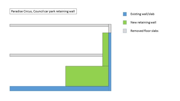 The blue wall has been temporarily propped with two levels of 45 degree square hollow sections that also prop off the existing floor slab. The design was intended to contain the lower prop and the upper prop would be removed, as shown in the Temporary propping arrangement.
Somewhere along the line, a mistake has been made either in the fabrication and installation of the props, or in the design of the wall. The lower prop now protrudes at the corner and is also required to be removed. With the base being poured in two levels (a mass concrete pour and a waterproof topper) these can be removed after the first pour.
Essentially the first base pour will replace the action of the lower prop so these can be removed. Our TW designer has asked the base concrete achieve 2/3 of the design compressive strength (approx 26.5N/mm2) before these are removed. Although in a gravity retaining wall, such as this, what affect does the strength of the concrete have?
I have a theory that the TW designer has tried to mitigate against the concrete being stripped out if it doesn’t reach the required compressive strength after the lower props have been removed. This would leave us up the creek without a paddle, as the upper props could not sustain the loading from the existing wall.
Update:
The props have now been removed and the wall hasn’t collapsed.

Just out of interest, and since the engineering looks fairly heavy did look to see if you could come up with an alternative temporary and permanent solution? from what I can see you end up, partially at least, with a cantilevered stem and the tension face steel is what it was before , only the lever arm has been altered ( by thickening)
I haven’t looked in to an alternative to be honest. There are some concept designs that had the section of the retaining wall the same thickness in the base and the stem. This was changed so the base of the wall comes to full height of the SSL.
At the top of the retaining wall approximately 10m back is the 130 year old, grade II listed building, the BMAG (Birmingham Museum & Art Gallery). Between the wall and this building are buried services that prevent any kind of anchoring of the wall back.
I guess sheet piling could have been employed, but the this would have increased the project programme. The site is still very much a demolition zone and the groundworkers are like ninjas jumping between 120T excavators and 350T mobile cranes! Bringing in piling rigs would require a huge footprint compared to what is available to the groundworkers.
I have had to deal with something similar but kind of in the opposite direction. I will post about it saturday but, in essence we cast ferrous anchors into the wall attached 16 mm adjusta bar bars then poured 1.2 m wide by 1 m of 50 MPa concrete in order for me to start backfilling after 2 days once the concrete reaches 20 MPa. If you can look at my post it is the wall in the middle of my site. This was all done for the temporary case of backfilling the spoil, once the slab on top is in it will restrain the wall.