Phase 3: Week 1…
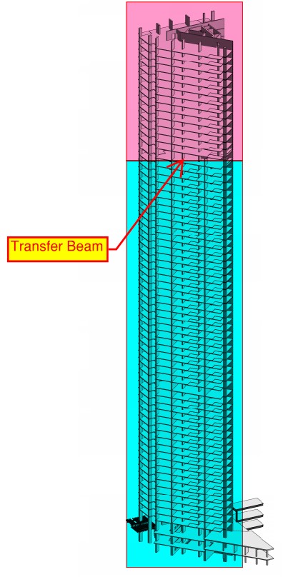
Since starting my Phase 3 attachment with Robert Bird Group last week I have been tasked with evaluating the current conceptual design of a 70 storey building. The main effort in this exercise was to see if the column layout could be revised to maximise floor space in the upper floors. An impression of the structure is in the figure below.

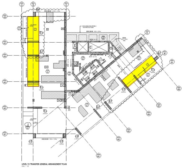
The current design sees a consistent column layout between Ground Floor and Level 53. Above Level 53, the layout changes to maximise floor space in the upper levels. My task was to evaluate whether the Level 53 transfer beams, would still work if they were moved to Level 47, without changing their geometry. The main consideration here is the additional load on the transfer beams caused by Levels 47 to 53. An illustration showing the approximate location of the transfer beams is in the figure below.
A plan of the structure is below. The two transfer beams have been highlighted.
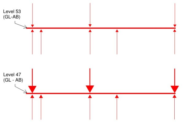
A simple sketch indicating the loads acting on one of the two beams is below. There are three columns acting as point loads on the beam, with five supports below the beam. Moving the beam lower in the structure simply changes the magnitude of the loads.
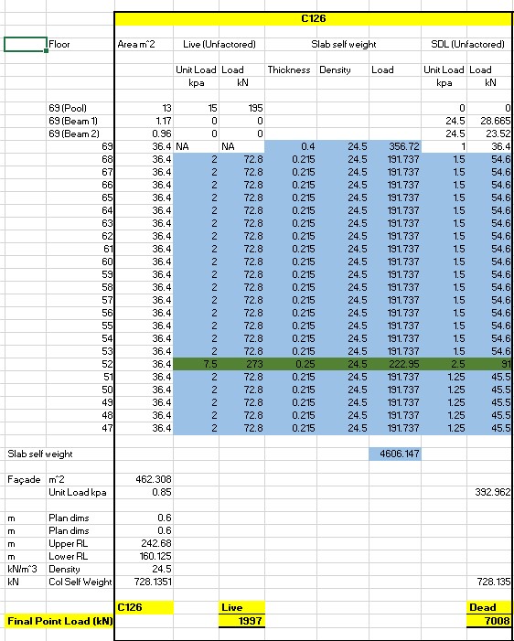
Once I understood the intent, I set about analysing the loads. I captured the loads acting on each floor and multiplied them by the area of that floor being supported by the columns in question. This allowed me to work out the magnitude of the point loads acting on the beam. An example of my load analysis for one of the columns is below.
I then added the UDL acting on the beam and checked to see if the beam could perform under the new design loads. This check was performed using a software package, commonly used by Robert Bird Group – ‘RAPT’. RAPT is not too dissimilar to STAAD Pro.
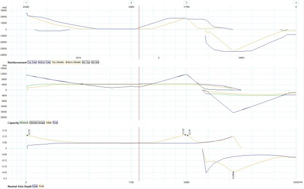
After running the check, I was able to confirm that the transfer beams could continue to perform as designed, without changing their geometry.
A relatively simple task, ideal for dusting off the Structural Analysis notes.

Mate, Great blog post – Interestingly I am doing pretty much the same at BM Head Office. I am currently living the RAPT dream looking at redesigning the slabs of Jewel in Surferes paradise (www.jewelgc.com) What value management do you do? For example – cutting down steel or slab depth. From what I have seen already is the consultants structures are tremendously inefficient – I have taken a 800mm slab and brought it down to 600 mm and the 1000 mm pool slab down to 400 mm (albeit being slightly inefficent with steel but making a common soffit).
With columns directly in line there’s barely any analysis to be done of the element as modeled. The issue with location is probably more to do with the performance of the structure as a whole. Hopefully any comment you have made has been accompanied by the caveat that the analysis applies to the capacity of the element only and no check has been conducted with regard to the structure as a whole, which must be thoroughly investigated as part of any proposed modification. Jo might like to add comment on the location of stiffeners and spreaders in a high rise structure given the issues at Aus 108 and her knowledge of high rise construction. This is likely to cause deflection, and sway issues!
Doug, I agree that many of the designs appear inefficient at the outset. From my perspective I was suprised at how much priority is placed on other, initially less obvious, considerations in design. For example our GF slab is 450mm thick providing 20kPa capacity. This is well in excess of the load applied by a nice desk, two receptionists and a fancy fish tank likely to load the slab in the permanent condition. The slab depth was therefore designed solely for the high construction loads applied for our top down methodology. In summary, elements are often designed for less obvious conditions than the long term permanent one. To that end the structural engineers might have good reason for the pool slab being 1000mm. Accoustic performance is another reason many of our slabs are larger than you would actually need simply for the permanent load conditi
Doug, I also agree with regards to inefficient design. I saw a great deal of this when on site. Although, like Tom, I also subsequently found less obvious reasons for what initially appeared to be over engineered members.
Rich, I absolutely added the caveat you refer to in you comment.
Doug,
You make an interesting point and whilst I was on site it is one that I entirely agreed with, and inefficient design frustrated me regularly. However, the boot is now on the other foot as I’m working for a consultant and I see more of the grey areas and pound signs (or dollars in your case).
I think you’ll probably find that the designs that you are getting are pretty much what the consultant has been asked to produce – I expect there would be angry emails flying back and forth if that were not the case. There is risk in all designs and I would argue that the more you value engineer a design (particularly early on when there are so many unknowns), the more risks you are potentially introducing, or the more constraints as to how the element can be used by other consultants or the contractor. With the design comes liability – if you’re not getting paid to hold the liability, then why value engineer the design? We are certainly asked to be very aware of our brief and not exceed it.
As an example I’m currently involved in checking steel connections following a failure of a connection during the service life of the building. It looks likely to head to court between the structural consultants and the consultant that did the detailed design of the connections and I’m sure lawyers are busily reading the contract small print now.
Tony