Steel Connection Failure
I remember with joy the moments in the Phase 1 lectures when the Lecturers outline various design approaches (let’s call them easy, complicated and devilish), and then tell us to draw a line through complicated and devilish, “you’re a fool if you choose those options, we’ll focus on the simple option for this tutorial”. Brilliant news.
Looking back through my Steel connection notes this is exactly what I’ve done and all of my Ex Steel joints were designed as simple connections (i.e not moment connections). However, it’s not always possible to draw a line through the difficult options.
One of the projects I’m working on over the next few weeks is the back analysis of steel connections in a building which has experienced a failure during use (a loud bang at night as one of the connections failed). I’ve still got a lot of work to do but below are my initial musings from SCI P207/95.

Figure 1 – Failure of B33 to C13 connection
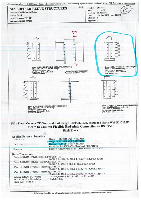
Figure 2 – Steelwork contractor calculation output
The frame was designed by my consultancy and a steelwork contractor designed the connections. The design of the connections was carried out using Masterkey software to BS 5950. The BS states that when the design is handed from a Structural Engineer to a Steelwork Contractor the contract documents and design drawings must adequately define the design requirement for the connections. Further guidance within the National Structural Steelwork Specification for Building Construction states this information should include:
- Design concept
- Member schedule and drawings
- Design standard to be used – in this case BS 5950
- Forces, moments and combinations at each connection – some raking/angled beams also have an axial force to consider.
- Factored or unfactored loads used
- Restrictions on joint details
My task is to back analyse the connections designed by the Steelwork Contractor, using the same software in order to check their connections for revised actions. The reason the actions have been revised is because regardless of whether the connections were designed as simple or moment connections (the two simpler design approaches), the reality is that there will be a degree of deformation at the connection, therefore the joint will really be acting as semi rigid with some degree of rotational deformation. If the connections is partially deforming then part of the moment will be transferred into the adjacent beam, in the case of a double beam to column connection, and part into the column.

Figure 3 – Classification of moment connections as per SCI P207/95
Initial investigations have shown that some of the “simple” connections may be too robust to act as a simple connection, and will in reality transfer some of the moment through the connection. Take note McClure – you shouldn’t always go big early.

Tony,
I have very little of value to add to this – although I have been told I will be defining the design requirement of steel frame connnections before it goes to the steel contractor. I will be interested as to what you find could have avoided this problem – assuming it wasn’t just poor practice on the steel contractors behalf?
Chris
Chris,
I’ll post an update when I’ve dug deeper and I can find someone to explain the long words to me.
In the meantime I’d recommend you get hold of a copy of SCI P207/95. We’ve only got a dog eared hard copy as it’s been discontinued now otherwise i’d send it electronically. The guidance in there is alot clearer on this topic than the new EC3 SCI guide. If the old bloke in the corner of your office hasn’t got it then give me a shout and i’ll scan in what i think you’ll need.
Tony
What size are those bolts? They don’t look to be 25% larger than the plate thickness to me. Have you measured the gap and the length of the beam? Looks like the beam is a little short of a snug fit but it’s hard to say from one photo. The partial fixity design case is interesting and a classic application of slope deflection or Moment distribution to obtain rotations and associated forces although I suspect thermal contraction might be another interesting area to look into.
Richard,
The failure happened previously and the immediate cause was obvious once measurements had been taken. The connection was undersized due to a miscommunication of a design change. Why/how this happened is still to be determined by a formal investigation but my TMR 4 will speculate. The process that we’re going through now is the re-checking of all the connections with the revised end reactions so that we can prove to the client that no more failures will occur.
The investigation flagged up a few more issues that would otherwise have gone unnoticed. These are higlighted in the answer to JMs points below.
A number of issues:
Looking at the photo I’d say that:
a) this is a simple connection
b) that the bolts are undersized as against the calc sheet which suggests Gr8.8 20 mm dia
c) The calc sheet implies SCI 212 ( simple) connections and a shear of 840kN
d) that the bolts are in single shear
e) That 10 No M20 gr 8.8 dia gives 941kN ( shear is the limiting thing) the bearing ply thickness only really becomes an issue when the bolt group are in double shear
f) Since the design was by Severs 941 playing 840 kN sounds about right
g) The design software is MasterSeries so NOT CNC linked to fabrication
h) The section that has broken away is heavily asymmetric; therefore it is almost certain that it was designed as composite with the reentrant deck profile it supports BUT I cannot see evidence of shear stud connection- how might this alter the behavior?
So I wonder….was the bolt size transferred into the fabrication shop in error and was is that there was nothing much ‘foregiving ‘ then error
ON you comments: I am not certain why you are thinking about joint rotation/moment behavior – it looks like a shear failure of a simple connection
Bloody interesting though – interested to see how this evolves
John,
a) yep
b) difficult to tell from the image but i believe they are M20.
c) The calc sheet implies that yes….but interestingly we were only sent the summary sheets which hides some important info (I would hasten to say not deliberately hidden). The dimensions of many of the connections I checked did not comply with SCI 212 and were too rigid to be a true pinned connection. We now need to check the failure mode of the bolts/endplates to check if they allow plastic deformation (mode 1 or 2 at a push) and allow the connection to “fail” to a pinned behaviour. Some of them don’t – hence the need to look at semi-rigid connection behaviour (thankfully not my job). But quite interesting to see. The worst case is the mode 3 brittle bolt failures.
d) -g) agreed.
h) I can’t remember if this one was designed as composite, but some of the beams, particularly the longer cantilever sections, were. When i quizzed the designer about this they said that they try to avoid relying on composite action where possible – it adds complexity. However, it would reduce the end reactions that the connection has to deal with. One particular connection I checked was way under designed for the revised reactions and composite action had to be used in that case to prove that it would work.
Tony
Are you sure that the connection details are for your picture. If so I find it hard to see the column that it is attached to.
Neil
Tony, I feel I should speak up in defence of the ‘go big early’ philosophy as Mclure and myself were big advocates of it during phase 1! I have just finished a Cat 3 check on a steel frame in Burma where the designers have tried to save money by picking smaller sections that were on the limit of passing for some of the columns. Unfortunately they have underestimated the load that will be taken by the columns and consequently calcs/models show them failing in buckling. I am now recommending that they ‘go bigger’ in order to stop them buckling.
In relation to your problem it looks like they didn’t go big enough with the bolts. Let me know how it turns out..
also, if you do get particularly stuck in any area get in touch with David Brown (the chap who delivered the lecture on portal frames to us). He’s on D.Brown@steel-sci.com (01344 636533). He is the go to guy for all things steel when the rest of the design office is out of ideas.
I had some queries regarding why certain annexes in Eurocode 2 were used and he was extremely helpful…..even went as far as to check my calcs!
Tony
Really interesting blog nothing intelligent to add… Cannot believe you flamed my go big early philosophy!