Archive
A really big crane.
I thought this may interest a couple of the civils.
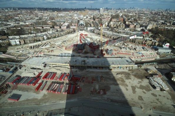
Keltbray have just erected the UKs tallest land based crane. The crane is to be used for the demolition of Market Place Station at Earls Court. The demolition requires the removal of all the station buildings (simple enough) and also all of the portal beams that span the underground lines running underneath the site (not so simple). There are 61 portal beams in total with weights varying between 200 tons and 1400 tons. The original plan was to break out each beam by cutting them into 20 ton sections and then lifting each section out. This would have taken up to two years to complete the beam removal and would have also resulted in numerous rail closures (in London’s current strike-riddled system this would have heaped even more misery onto commuters). The demolition plans were nearing approval when some bright spark decided to ‘go big early’ and suggested using a massive crane instead. The plan would be to make a cut at either end of a portal beam and then lift it out in one piece. This idea would shave years off the project program and was selected as the method for removing the portal beams.
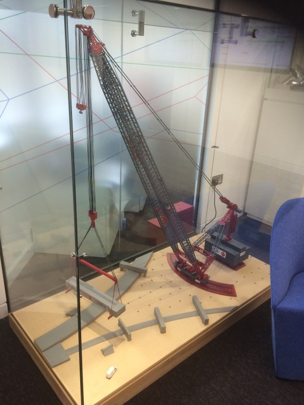
As a result the crane has just been erected at Earls Court:

It stands at nearly 120m high and has a counter balance weight of 12000 tons.
Everyone at Keltbray is very excited about it.
HELP
Does anyone know anything about HV installations in Camp Bastion and/or Camp Leatherneck?
A Channel 4 documentary reliably informed me that the ES compound had a HV system, but TICRE has no info on it. So if anyone can point me in the right direction, or even just make up some thing that I can then reference that would be great. Thanks.
Agora Tower, Taipei, Taiwan
Check out this building!

http://en.prnasia.com/story/126403-0.shtml
http://www.designbuild-network.com/projects/agora-tower-taipei/
http://www.designboom.com/architecture/vincent-callebaut-architectures-agora-tower-taipei-taiwan/
![]()
Gloucester the building not the place
Introduction
Whilst working on HPC has been interesting, there is a limited amount to learn from the experience so I have negotiated severing my involvement in the project. I have recently been working on an electrical study for a security clearance “building” located in Gloucester.
This building has critical equipment and therefore employs an Uninterruptable Power Supply (UPS) to guarantee the power supply to the data load and the cooling plant for the equipment. Unfortunately there was an electrical fault (exact cause are unknown) which caused a fire – damaging the UPS system and a distribution boards. The building is still operational utilising the UPS bypass as a temporary solution.
Replacing the damaged system, presents the client with an opportunity to increase the capacity of the building, therefore Atkins have been employed to conduct an electrical study.
A site investigation by the DV cleared electrical lead, gathered a snapshot of the electrical loads and the maximum recorded kW for each system.
Electrical Supply
Transformer 1 (TX1) – 11kV/400V rated at 800kVA
Transformer 2 (TX2) – 11kV/400V rated at 800kVA
3x Combined Cooling, Heat and Power Load (CCH) – 310kVA (N+1 configuration therefore 2 in use and 1 as backup)
Reflection
Designing a system from the start is straight forward because the designer can use design loads of the equipment and make assumptions based on justification. Making recommendations on replacing equipment without the design loads of the equipment or data of the electrical demand profile is a difficult situation. Using the maximum recorded loads identifies the worst case scenario, however combining all of these maximum will significantly reduce the extra capacity for expansion. Whilst using the electrical loads from the survey provides a more realistic figure but the survey could have been conducted during a low demand period. Therefore all the recommendations made by Atkins are caveated by “the recommendation for energy data loggers to be installed for a month to give an indication of the current kW on the system to confirm suitability prior to installation of a new load”.
It comes back to T/C/Q. The client Interserve want a quick solution – the UPS is a critical part of the system therefore its quick replacement is essential. Whilst Atkins focus on a quality product in the hope of winning more work off the back and building their reputation/relationships with the Client.
Spare capacity
Using the electrical demand provides the following spare capacities:-
TX1 –427kVA (53%)
TX2 –264kVA (33%)
2x CCHP –239kVA (38%)
It is important to understand the system operation before making recommendations on expansion. In the event of total failure of the CCHP, the load would be switched to the TX2 and the UPS would provide the supply during the transition. Therefore the potential increase of the data load by 239KVA supplied by the CCHP will limit the potential capacity of TX2.
TX1 –427kVA (53%)
TX2 –25kVA (3%)
Further Analysis
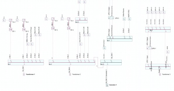
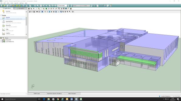
I am currently modelling the building in AMTECH (similar to Hevacomp) see picture below, in order to conduct further analysis on increasing the electrical demand and the potential limitation due to current carrying capacity of the sub-main cables and potential changes to fault protection.
Sustainability Initiatives in Practice?
Recently, I have been on the periphery of some environmental work by RPS and I thought it may be vaguely interesting for the blog.
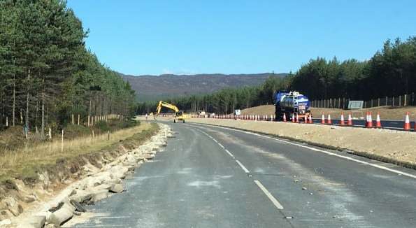
A9 Upgrades – Proof that the sun does shine in Scotland
As part of highway improvement works north of Perth, a Joint Venture of Wills Bros/John Paul is upgrading a 7.5km section of the A9 between Kincraig and Dalraddy. The scheme passes through the Cairngorms National Park, Alvie SSSI (site of specific scientific interest) and a tributary of the River Spey SAC (special area of conservation).
The project has required the management of numerous protected habitats and species during the construction schedule and RPS has provided Environmental Clerk of Works (ECoW) services.
My involvement has been compiling some reports but I thought it was interesting how much effort was expended on a relatively small contract (value £35m). The ecological highlights of the project included:
- Translocation of some 45 Hairy Wood Ant nests in collaboration with the Cairngorm National Park Authority. Hairy Wood Ants are included on the Scottish Biodiversity List as a priority species for conservation. They are a key stone species of woodland ecosystems and are threatened through habitat loss.
- Sensitively felling of mature Scot’s pine forestry containing Red Squirrels in consultation with Scottish National Heritage. Red Squirrels are protected both under UK and European legislation.
- Installation and monitoring of Otter fencing surrounding the development to protect this qualifying species of the adjacent River Spey SAC.
RPS ECoW services involved monitoring of compliance with all relevant environmental documents. In short, RPS was the contractor’s own environmental police. The environmental element of the project was considered a great success. The successful translocation of the Hairy Wood Ants was praised by the National Park Authority and the sensitive removal of forestry ensured a negligible impact to the local Red Squirrels population. Whilst the Otter fencing monitoring gave confidence to SNH that the development caused no likely significant effect to the nearby SAC.
From my cynical perspective it is interesting to note that the effort expended in aid of the environment has been rewarded. RPS site team have received high praise resulting in a score of 9/10 (“exceptional”) for environmental protection under the Considerate Contractor Scheme. The benefit of the full time environmental presence was recognised by the stakeholders. They had confidence that regulations were being followed; the site achieved a very high score for “Protection to the Environment” in the Considerate Contractors audit which rated the site as “Excellent”.
Maybe some of the environmental sustainability initiatives do work?
They said I was mad to build a castle in a swamp!
Monty python-Holy Grail
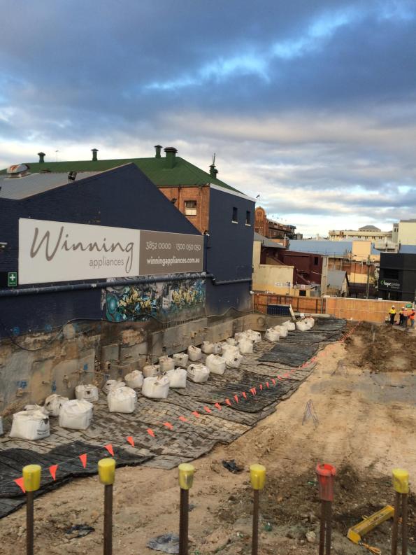
In my last blog I mentioned building a basement in a swamp. The tender is on a brown field along a tributary of the Brisbane river known as Breakfast Creek. The site that has recently been cleared (ish). On my recce I began to feel a sinking sensation in the pit of my stomach. The ground here is truly awful but, the client is adamant that he wants his basement.


Design. The structure is a 6 storey Mercedes show room/car museum with a single storey basement. The client’s design calls for a temporary retaining wall and then a concrete bath tub to keep it watertight constructed on the inside temp retaining wall. The structure itself will be supported by pile footings. It was originally tendered as a Traditional construct only package but, due to the risks is now being let as a Design and Build.

Boundary. Argillite bedrock between -7 and -31 m. Level of Bedrock varies across the site from -7 m in West to -31 m in the East.
Properties. Very Soft Alluvial Clay φ’ = 25 ° and c’ = 0 until Hard Argillite Rock.
Groundwater. Tidal range of RL +0 to 2 m (+3.5 m flood level)
Contamination. You guessed it ASS is back. With some potential hydrocarbon contamination.
Issues. The client wants this basement even if it costs him $5 Million.
- It is a swamp! It is possible to cantilever 5 m in this rubbish but the toe stability is the problem. The solution at the moment for sheet and contiguos piles is to have every 3rd pile down to the base rock which can be up to 31 m.
- The pile loads for earthquake loading are massive. Brisbane isn’t in a seismic zone but like all building it needs to be design to withstand a basic seismic. The problem is that because the neighbouring soil isn’t worth a damn the tension loads carried by the pile foundations are over and above what you would expect of a 6 storey building.
- Hydrostatic slab. Given the high ground water level, the basement needs to be designed for a hydrostatic slab. The original design calls for beams to carry this load but, this will be a nighmare for something that cannot achieve a batter of 1:2.
- Heritage structure. An existing heritage bridge abutment (not in use) is on the perimeter of the site and it cannot be damaged, despite the fact that it has failed.
- Existing retaining walls. The client also wants to keep any existing retaining wall structures that have been left in place. Unfortunately, the existing retaining walls from the previous structure show signs of distress. It appears that their is disproportionate settlement in at least one part of the retaining wall. To make matters worse there are no as-builts of the retaining wall structures.
Upside – The hotel where I took this photo does massive steaks and great red wine – so that’s how I spent the afternoon. If all recces were this good
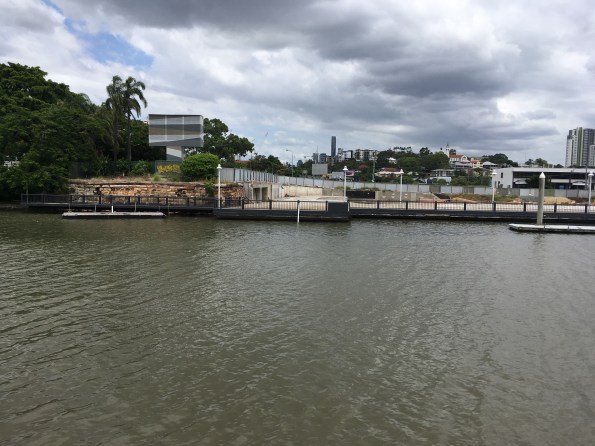
View South from opposite bank (bar). Failed heritage abutment on left. (Note high tide)
Calcs v Real World
Hambly’s Paradox…

A man weighing 600N sits on a three-legged stool. The stool is symmetrical, the man sits in the centre of the seat. What basic force should each leg be designed for?
The same man now sits on a square stool with four legs, one at each corner, the stool and the loading are symmetrical. What force should each leg of the stool be designed for?
Rock blasting in the middle of the city!
Blasting next to a heritage bulding in Fortitude Valley, Brisbane City
So I am currently assessing how to build a 4 m basement car park in a swamp with a CBR of 1.5. I could go into the details of that but, while researching my thesis I came across these videos of blasting in two of my case studies Fortitude Valley and 300 George Street which are far more interesting. How do you get away with blasting very hard rock in the middle of a city? With a lot of careful planning. Note the mattresses to prevent fly rock and the drilling before hand in the 300G video not just for placing the explosives but to localise the effect of the shockwave

Details of the blast
Building Energy Efficiency
How do MEP engineers design a building for energy efficiency? This was a question that had often kept me awake at night…. fortunately thanks to the first few weeks at a design office I have an idea of how the process works. This blog will briefly run through the process of designing the building MEP to specify equipment and meet the UK energy efficiency (Part L) building regs.
Building thermal model in IES – Hevacomp for grown ups
First of all some principles of how the design office operates (so far):
- Minimise time. Time is money for the design office; they are very fastidious about budgeting time to a project in advance and accounting for the time spent. Therefore only the minimum design work is undertaken. g. pump size on the longest pressure drop, don’t both with checking anything else.
- Deliverables drive the project. In conjunction with the previous point; Bryden Wood will only produce a model when they are required to do so, otherwise Excel is generally used to do the job. In my first project the client has paid for a Revit model update every two weeks, but all equipment sizing is done on Excel. The data in this model is minimised to limit time wasted; for example pipes are shown uninsulated as it would take time to draw it on, drawings are not colour-coded, etc.
- Energy Efficiency Legislation is met (just). There is no advantage to the client of smashing the energy efficiency legislation… this would just waste money. The equipment and building materials have been spec’d to meet the legislative requirements and no more.
- Minimise Responsibility. The MEP team is only able to influence a small element of the overall building performance; designing MEP equipment. Unfortunately we are required to predict the entire building performance – which is influenced by the number of windows (architects), orientation (arch), structure (civils), etc. Therefore time is spent recording other stakeholder’s decisions to protect BW if/when the building fails the performance checks.
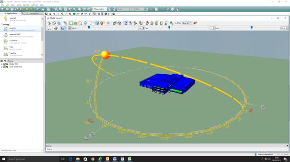
Sun path graphic for Barnet leisure center. The program will include solar gains for rooms.
My first project has been the MEP fit-out of two leisure centres in North London. In very simple terms the design process has been:
- Develop Strategy. A scheme for the MEP design is developed based on building use and client wishes. This is generally based on experience within the design office and the clients’ spec; for example the swimming pool will be served by an Air Handling Unit (AHU), Café will have underfloor heating, etc.
- Rough Equipment Sizing. This is undertaken on a big Excel spreadsheet with details of temperatures, room internal heat loads, fabric losses etc. All very reminiscent of the PEW design exercises, based on CIBSE or ASHRAE references. Loads are summed (with a bit of fudge factor diversity) to give approximate plant loads for the building.
- Select Manufacturers. The client has a list of preferred manufacturers who get involved with selecting the equipment for role based on the rough loads calculated above. This stage has an element of project management to it, and a few free lunches.
- Develop Thermal Model. Dedicated Integrated Environmental Solutions (IES) software is used to model the thermal characteristics of the building, in parallel to stage 3. This adds more accurate numbers to allow detailed plant sizing and includes solar gains, heating profiles, etc. The full potential of this software is not used to save time – for example, instead of modelling the transient (or warm-up load) for the building the equipment is sized on the steady-state load +15%!
- Confirm building meets Part L. The IES program is one of four approved to determine whether a building will meet the legal efficiency requirements. Detailed system information is added once plant has been selected, then the program produces an Energy Performance Certificate (EPC) and Part-L compliance certificate.
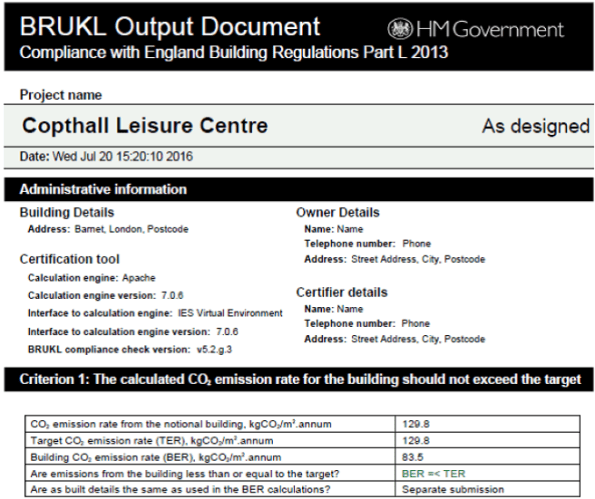
The finished Part-L compliance report
In all this process will have taken a team of three about 12 weeks to complete… a bit more relaxed than the single week we are given on the building services design exercise at PEW.
Permissible Stress or Limit State Design?
Hopefully this blog won’t be as boring as the title suggests?….
Even though it was a very long time ago….. I remember being at university and learning about permissible stress design (it obviously wasn’t a Thursday morning). At the end of the lecture a wise old professor informed us all that we’d never actually design anything this way, that it was pretty much obsolete because everything was moving well and truly towards the future…. and the limit state approach. Indeed, when I worked in industry prior to joining the military I found this prediction to be true, and the idea was reinforced during Phase 1!
Imagine my surprise when I arrived in the US and found that, rather than being a bastion of enterprise and advancement, the US actually embraces and encourages the two design philosophies to be used in parallel! Over here they are known as ‘Allowable Stress Design’ (permissible stress), and ‘Load Resistance Factor Design’ (limit state). When I say ‘encourages’, this isn’t quite fair. What I mean is that the American Institute for Steel Construction (AISC) publishes both methods side by side in its design manuals, allowing designers to pick which method they prefer. Interestingly, concrete did make the jump years ago, and no longer practices ASD.
So I’m currently designing a glorified giant dog kennel and training facility for some fierce secret service working dogs. I’m working to ASD for the steel and masonry, which is nice because it makes things simpler and I don’t have to worry about any complicated plastic analysis or behavior etc…. it’s also handy because all of the joists come from the manufacturer designed and specified using ASD. Nice and simple. Until it comes to designing the footings, which of course being concrete mean that I had to alter my loads using a crude conversion factor of 1.4 to ‘upgrade’ them from ASD service loads to LRFD design loads! But even then the fun isn’t over; the soil bearing capacity (4000psf John, very stiff!) isn’t factored, so I need to multiply this by an additional ‘resistance factor’ so I can work in LRFD, making sure I don’t accidentally divide by the ASD global ‘safety factor’ instead, because that would be a disaster! Who needs a sinking building and (expensive) squashed mutts!?

My Design: Permissible Stress or Limit State? Why choose, have both!
Apparently things are improving! Until recently live load and dead load factor of safeties for steel and concrete construction using LRFD where different! 1.6 & 1.2 for steel and 1.7 & 1.4 for concrete; imagine having to swap between the two sets whilst working with the same philosophy on the same design! You all thought Euro-codes were frustrating, you’ve got it easy! Also, (and back to the point) the AISC are apparently considering removing ASD from their manuals which will be a step in the right direction! However I’m not holding my breath; it takes a long time to buy a stamp over here, imagine how long it might take to alter something as ingrained and controversial as this.
This all seems like madness and an accident waiting to happen… and it nearly it! During my time on the JOC project over at East Campus it was discovered that a series of giant steel trusses had been sub-contracted out to a ‘specialist’ by the designer. When they were finally delivered to site it was discovered that they, together with all the connections had been designed using ASD rather than LRFD loads. On checking the truss turned out to be fine (phew, almost a very expensive error for someone), but all the connections were under-designed by approximately 40%! These trusses were very nearly installed, and it was only scrutiny of the drawings at the beginning of the week of installation that prevented fundamentally unsafe construction! Whilst it is considered bad practice to mix design philosophies, in my experience it seems to happen an awful lot. Particularly on simpler, small projects that need to be turned out quickly, and by older-generation engineers who grew up with ASD and see no reason to change.
I was wondering if anyone else had had any experience of permissible stress design during their attachments? Surely if there’s a slow backwards nation that can stand with America on this one it’s Australia?! Or is it really only America that lacks the will to embrace change?
