Airport East; Demonstrating the Ground is a Risk.
Background
Sydney Kingsford Smith Airport and Port Botany are two of Australia’s most important international gateways. The roads around the airport and Port Botany are becoming increasingly congested due to the rising numbers of passenger and freight vehicles. The Airport East Precinct project will support the development of the West Connex motorway, which will improve access between this area and Western Sydney.
Project Overview
The Contract is for road and rail bridge construction on General Holmes Drive, Botany Road, Wentworth Avenue, Joyce Drive and Mill Pond Road in the east precinct of Kingsford Smith Airport at Mascot.
As site engineer I am currently overseeing elements of the installation of a new two span reinforced concrete bridge linking the new Wentworth Avenue underpass to General Holmes Drive (GHD) shown in figure 1 and tendering for the precast bridge planks.
The site is heavily congested and restricted, an active freight railway line dissects the centre. A sewer, high pressure gas line, and canal also create obstacles which have load limits imposed on them; therefore manoeuvring machinery is posing to be a real headache. There is also a vertical limit of an obstacle limitation surface; this defines the airspace surrounding Sydney Airport that must be protected from obstacles so aircraft are free to descend without interference landing.
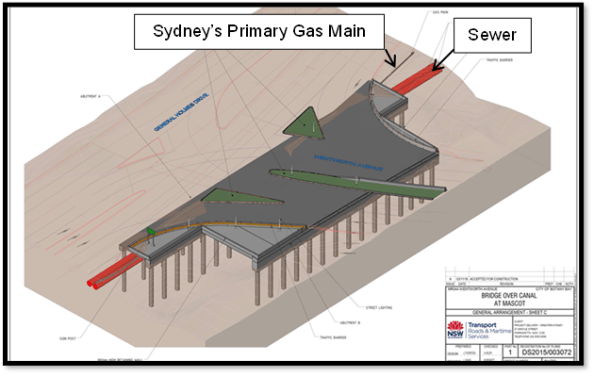
Figure 1 – Bridge Linking GHD to Wentworth Avenue Underpass
Vibration Management
The east runway is undergoing maintenance from 24 March 17 – 3 April 17 which allows the tall piling rigs to be set up. I have noticed rotary aircraft using the eastern side of the runway so have suggested that red warning lights (complying with Civil Aviation Authority Standards) are attached to the top of each of the piling rigs and included in the activity method statements.
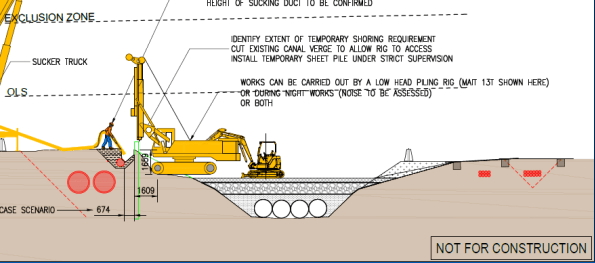
Figure 2 – Non-destructive Excavation & Sheet Piling Stage
A sheet pile wall will be installed adjacent to the primary gas main that will serve two functions (figure 2);
a. Retain the existing ground profile and allow for backfill around the gas main to eliminate any potential settlement or subsidence through piling and bridge substructure works.
b. To provide robust sacrificial formwork for the capping beam / pile cap.
Prior to installation of the sheet pile, non-destructive excavation was used to determine the exact location of the gas main and extent of stabilised sand backfill around the services (figure 3).
During the sheet piling, vibration monitors have been installed along the sewer and gas main to record vibrations which may occur. Limits of vibrations which cannot be exceeded for the gas main are 20 mm/s and 5 mm/s for the sewer. If the vibration limits do exceed this, a silent piling rig will be utilised. I have questioned these figures as I was asked to research ground borne vibration on buildings within the area and DIN 4150-3 limits peak particle velocity to 3 mm/s on sensitive buildings.
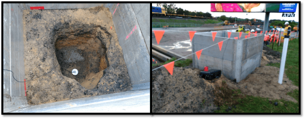
Figure 3 – Vibration Monitoring of Gas Main
The silent piler uses the ‘press in’ method, grasping the previously installed piles and establishing a reaction force from the negative skin friction and interlock resistance of the previously installed piles. Since the piles are pressed in this method does not cause any damage to the environment including neighbouring structures, assets or residents through noise and vibration.
Contamination
The project site is contaminated with poly-fluoroalkyl substances, known as PFAs. These are a group of manufactured chemicals contained in firefighting foam, they are added to improve the foams ability to smother fires. Therefore the likely source is Sydney Airport, the drainage for the airport runs through the site. The pathway and transfer of the PFAs is via the natural ground water flow through the site, and the possible receptors are workers and local residents as excavation occurs. They are a carcinogenic but are not found in high enough concentrations in the vicinity of the site to cause harm to workers.
Continuous flight augering (CFA) piling is being used due to the poor ground conditions and lack of cohesiveness of the loose, brown/grey fine to medium SAND. This method of piling stops the excavation collapsing due the concrete being pumped in as the helicoidal auger is extracted to give positive pressure to the excavation walls.
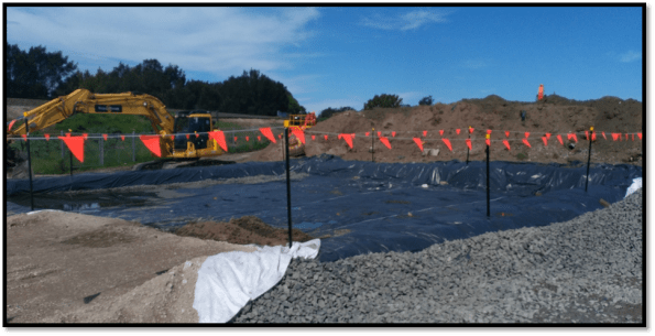
Figure 4 – PVC Barrier Layer for Spoil Heap to Limit Contamination
Excavated spoil is going to be placed in spoil heaps as to not contaminate the top soil. The PVC sheet is used as a separator and for the site to be compliant with the Australian Environmental Agency requirements. After looking at the design borehole (figure 5) for the site, I noticed the differing concentrations in PFA’s across the site. I have suggested that separate spoil heaps are created for different areas of excavation as to not waste money in disposal of contaminated waste which is has a different concentration of PFAs.
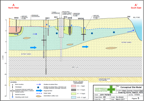
Figure 5 – Design Borehole for Site
CFA Piling Issues
As stated earlier the ground conditions are dictating that CFA piling is used. There have been some difficulties though when driving the cage into the poured concrete. Even though the water table is -3m AOD the loose, brown/grey fine to medium SAND is absorbing the moisture content of the concrete causing the concrete to cure quicker than expected. The concrete used has 240mm slump and aggregate size of 10mm (primarily to fit down the CFA tube). To overcome the issue 2m of concrete is being poured then immediately drilled out, lining the excavation with a layer of concrete to mitigate the loss in moisture content. Currently an excavator bucket is being used to push the cage into the concrete, but vibration of the cage is also being looked into. Thoughts on the use of a plasticiser?
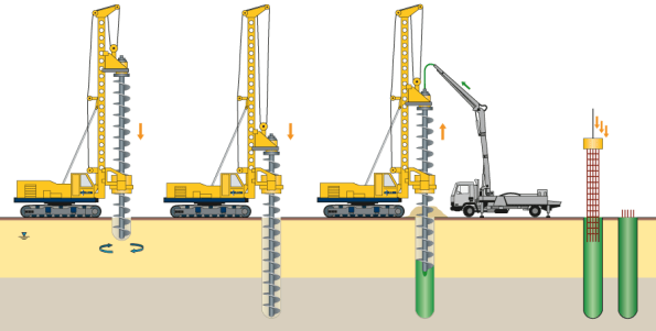
Figure 6 – CFA Piling Process

It would be interesting to ask the question was rotary bored piles under fluid support considered?
Fluid support during piling can normally be engineered for pretty much all strata.
In my experience CFA piling is not always selected because of ground conditions but other reasons (noise, vibration etc).
Could the CFA piling have been selected because of the aviation restrictions?
Whole range of things here:
On the effects of piling see SCI C308 p22 there is a rough method of assessing the ppv associated with piling Roughly proportional to the square root of the equivalent hammer weight and inversely proportional to the distance at which the ppv is to be measured.
If you look at BS 7385-2: 1993 you can see two important influences:
a) Low frequency <10Hz tends to be more damaging that high
b) Continuous is more damaging that intermittent
What you show as a 'design borehole' is in fact a conceptual model for contamination . It shows the migration of the PFO PFHxS plume – I think this is what you mean when you say PFA ?
ON the CFA piling I agree with RIchard M I would find it surprising to undertake CFA beneath the water table in coarse grained soil unless the Botany Sand . The geology is that this is comprise uniformly graded (well-sorted), clean, poorly cemented fine to medium grained quartz sand. This means that CFA without drilling fluid sounds like a very bad idea. Moreover the uniform grading would means the a the implied suctions would be low ( even if the sand is fine) So I am perplexed about the rapid drying. IF it is a problem I guess that a plasticizer or retarder would be appropriate?
Out of interest if you are experiencing problems with the installation of the piles then what assurance is being carried out? What percentage are you conducting load tests on and are you carrying out any form of non-destructive testing to check the piles integrity?
Vibration Monitoring
Thanks John for BS 7385-2: 1993, looking at Table 1 on page 5, the nearby church is experiencing 8mm/s at greater than 4Hz, therefore no structural damage should occur. I doubt though the structure is closely following the movement of the ground due to the unconsolidated sand, therefore the structure can only sustain a lower ppv. I believe a risk could be consolidation of sand and differential settlement under the structure.
Contamination
The PFA’s, were called PFOs and PFC’s but the Australian Government has put them under the collective group name of PFA’s due to confusion with another group of chemicals that were relevant to climate change.
CFA Piling
John Holland has subcontracted the piling to Keller, Keller have opted to use CFA piling for the over bridge of the sewer, gas pipeline and sewer mainly due to cost and time (CFA piling of 6-7 piles per day compared to 4-5 bored piles under fluid support, we also have to remember the contamination and cost of disposal of the fluid). The CFA piling over the canal are only 10-11 m deep but on the rail bridge Keller are using driven sleeve piles for the large railway bridge abutments (32m deep).
Soft/loose unconsolidated material can accumulate at the base of the bored pile, if the excavation collapses. This may have a seriously negative effect on the serviceability of the bored pile as well as reducing the ultimate pile capacity. CFA piles are not highly reliant on their end bearing, the majority of their load capacity is derived from skin friction. During excavation air is introduced into the auger stem to keep positive pressure on the inside of the stem which prevents the ingress of water. This also prevents any concrete segregation inside the stem which in-turn helps to stop blockages when concrete is being pumped. The pressurised air also aids the drilling of the pile as it pushes the material up the flight.
Rejection of Reinforcement
Reference rapid drying, this interpretation with inserting the reinforcing cage has now been taken off the table, and replaced with the misalignment of the cage as it is inserted or a failure in the excavation wall prior to the concrete providing the active pressure to support the excavation.
Pile Testing
Cylindrical testing (cube testing) of the concrete (complying to the clients specification (Roads and Maritime Services (RMS))) along with Aurecon’s design of the CFA and reinforcement is satisfying John Holland. Keller are though dynamically load testing 3, of the 49 CFA piles which are being used in the canal bridge construction. Keller will monitor the response of the pile subjected to hammer blows applied at the pile head. The measured response parameters are subsequently analysed to give predictions of the soil resistance that would be mobilised by the pile under static load conditions, based on stress wave theory.
Due to the very high rate of applied loading, dynamic load testing cannot take into account time-related effects such as consolidation, relaxation or creep which I would assume would be prevalent in the loose brown botany SAND. I am moving on to Abutment B tomorrow (Wednesday), I will find out what care Keller are exercised in reviewing the results of tests carried out in soils which may exhibit these features. However, the use of dynamic testing after calibration within a particular geological profile will allow more comprehensive testing at low cost in comparison to static testing.