Slope Stability – Safe or not safe?

Figure 1 – 45 degree slope with 80T crane surcharge
Whilst wondering around site during my first couple of weeks I couldn’t help but notice the slope in the picture situated in River Terrace Gravels. Having now read the GDR I know the design phi dash of the River Terrace Gravels to be 33o. Therefore a design angle of Beta at approx 60o. When I queried a couple of the site/section engineers the response was that they always cut a slope at 45o and then step it if it is a larger slope. The layer below the River Terrace Gravel is London Clay and I would agree that for the short term in clay this would be sufficient, relying on the undrained shear strength. However is the design of 45o in the River Terrace Gravels acceptable?
Firstly a slope cut at 45o would still suggest a safety factor of 1.3, assuming that the pumping of ground water has reduced the ground water regime profile of the water level to below any slip surface. There is a sump reducing the water level to approximately 3m below the toe of the slope, so I will make this assumption.
I modelled this case in Geo5 (Figure 2), producing a result of instability. Geo 5 was showing failure in DC2 but not DC1. This is because DC2 is more conservative where a gamma factor of 1.25 is applied to the tan phi dash, reducing phi dash to 27o. As this is a temporary load case and we know phi dash will not be as low as 27o is this suitable for a temporary works solution?
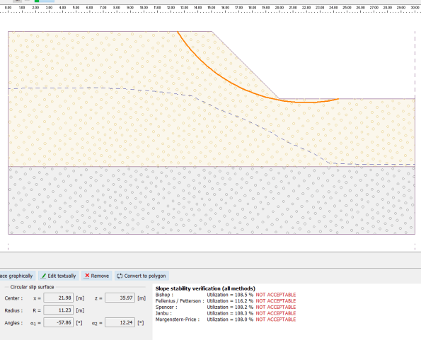
Figure 2 – Slope modelled on Geo 5
Moving on – As you will see in my photos there is a crane (80T) operation at the top of the slope, therefore once you take this load and factor by 1.3 (NA to 1990. NA.A1.2(C)) and re-model in Geo5 you can see it fails with a larger rotational slip. The crane is in fact sitting on a 400mm deep concrete blinding but I cannot model this without Geo 5 ignoring STR failure in the concrete pad. If I ignore the pad then obviously the situation is worse but the principal the same.
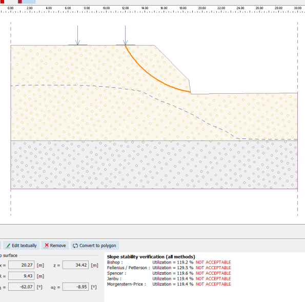
Figure 3 – Slope modelled with surcharge
The gamma factors in the Eurocodes are there as guidance and therefore I would argue temporary works is the ideal time to reduce them if considered safe to do so by the engineer (allowing for other factors). Is this an example of just such time when the ground seems to be behaving as expected or is this too great a risk. However currently there is no temporary works design for this slope and the surcharge inflected by the crane; so I would suggest it is too much of a risk!

A risk taken with knowledge and experience is judgment, a risk that exists but has been taken in ignorance of its existence is negligence. Necessarily, the risk might be the same in both cases, however hopefully in the former case the potential issues will have been mitigated. Whilst being ignorant is no defence, an even greater crime lies in knowing about a risk and doing nothing about it; here there is also moral, ethical and professional failure.
Hopefully you have either raised your concerns through the appropriate channels and documented this, or, made a note of your rationale for accepting that you are content that there is no undue risk (unless the situation changes). I think your conclusion above is that there is an unreasonable risk. Given that gamma factors are all about limiting risk to satisfactorily improbable levels of occurrence I would concur that this is not the time to ignore them. I would also suggest that the surcharge load from a concrete bearing pad and an outrigger with a boomed out load in an unfavourable orientation might just raise the surcharge to a higher value than you might have allowed. Make sure you raise this. If there is no formally appointed TWC, the client, by default, is responsible for inspecting the works and ensuring they are safe prior to being loaded, whether they know this or not.
Richard, I completely agree with you. If it was a design and calculated risk that a professional had made that would be one thing but I believe there is a failure of the other engineers on site not raising the question. I did raise this straight to the TWC and he has subsequently passed it onto the Temporary Works Designers.
Hi Henry, does that sheet pile wall extend all the way past the crane position and how deep does it go? It’s hard to tell from the picture but might it not cut right through the failure plane you’ve modelled, therefore providing stability? That concrete structure on the right also looks like it may be providing a bit of weight to the toe. It sounds like there may already be a number of mitigation methods in place to cater for the risk; weight provided at toe, bettered slope, groundwater table lowered, sheet piling used to prevent sliding.
Ed, the sheet pile wall doesn’t extent to the position where the crane is, it stops about where you can see the capping beam starts, and therefore it doesn’t influence the retaining of the slope or crane. You are correct; the concrete structure which is a capping beam on top of a diaphragm wall will provide stability to the toe of the slope. However, although this will assist in the slope stability, I still believe that there is potential for a failure plane to be created and the bottom line is that this slope hasn’t been designed for as a proper temporary works solution, so the risk has not been assessed.
Henry perhaps try and dig out the Activity Method Statement for the works, all our groundworks on the John Holland sites have to be signed off by a geotechnical engineer. That may shed light on to their design strategy or detail any comments made by the geotechnical engineer.
Henry, in the model is the yellow representative of the gravels and purplish colour the clay therefore the modeled failure plane is within the gravel?
Assuming this is the case then you are discussing shear failure within a coarse grained soil. So risking the wrath of John for getting this wrong; increase the total load for a coarse grained soil and for that immediate snap shot in time, the pwp increases proportional to the total load maintaining the effective stress. Effective stress is proportional to soil strength therefore, at the exact point of loading you will have an increased total load for the same effective stress and same strength of soil; so if it was going to fail, it would do the moment the total load was increased (i.e. the addition of the crane) before the permeability of a coarse grained soil permits the rapid reduction of pwp. increasing the effective stress and strength of the soil. This has clearly not happened. The risk of shear failure within a coarse grained soil is immediate.
Absolutely agree with all comments about mitigation of risk in that this should be a serious consideration before the addition of the crane – one that may have been assessed and deemed ok, or one that wasn’t and maybe they were lucky. However, if the slope was going to fail in shear, it would have done so already. Unless I’ve completely misunderstood some part of the scenario. Would be interested to know what you find out after some more digging.
Liking the blog and discussion
Without any surcharge, the theoretical failure plane ( in the absence of water) is 45+ phi’/2
So without any calcs the 45 degree slope is sound – in the absence of pwp and surcharge
So we come to your analyses: All good and where software is absolutely marvelous:
What are the risks?
1 Those we cannot mitigate
(a) The actual mass strength of the soil;
(b) The possibility of different failure geometries
2 Those we have a little control over
(a) The pore pressures
(b) The surcharge actions
1(a)Terrace gravels – we can assume they are recent and therefore we might immediately assume c’ of zero; What range of phi’ would you select? You’ve not much more than the classification and A+B+C to select the angle – The GDR will suggest and angle but should give a range the 33 degrees suggests a well graded gravel and looks on the moderately conservative side- the risk is mitigated(?) in tan(phi’)/1.25 in DC2
1(b) This is were software works well by hacking through hundreds of thousands of surfaces
2(a) What if the gw control system were to go down – how is this handled – spare pump? We might wish to look at a recovered regime and control the surcharge immediately if the gw control failed
2(b) Notwithstanding the differences in track loading caused by the slew, the actions associated with the temporary works is time bound and relatively well known. Here is where I would hope that you military engineers might think hard- along the lines that Henry is proposing. There is a 1.3 factor in the variable actions (DC2) and the clue ( I think) is in the word ‘variable’. In these temporary works is there a case for moving this factor down – it can be done in the setting of a load case in GEO5