Stadium Australia
Built for the Sydney Olympics, Stadium Australia originally looked like this…

After the Olympics, the stadium was expected to attract smaller crowds and so the terraces behind both goals were reduced. This modification has resulted in the present day configuration, see below.

The owners now want to make two further modifications. Now that the running track is redundant, the first alteration will see the seating brought much closer to the pitch, adding to the capacity and atmosphere. The second alteration will see the addition of a roof, see below.

Whilst both endeavors are intrusive, the alteration of the seating arrangement is the greater challenge. This is because the trusses which span over the length of the stadium were designed with a roof in mind – bonus.
The box and mid terrace which run the length of the pitch are cantilevered from the main structure. The lateral push / pull loads are transferred to the core via the floor plates. Without a balancing load, this would cause the core to deflect towards the pitch. To counter this, vertical post tensioning runs the full height of the core, on the wall furthest from the pitch, see below.
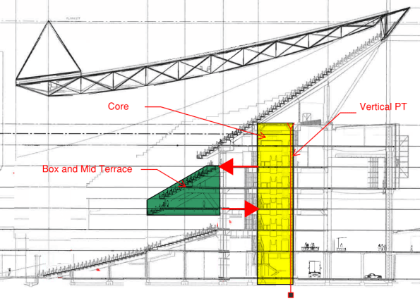
Key: green = terrace, yellow = core, bold red arrows = forces in floor plate, red line at back of core = PT.
To reconfigure the seating, the box and mid terrace will need to be demolished. The requirement therefore is to identify a methodology which allows the removal of the terrace without causing an unacceptable imbalance with the post tensioning.
My first intention is to track down the original construction methodology. Has anyone else been exposed to the modification of PT structures during their Phase 3? Suggestions on a post card please…

Having spent yesterday working on this I thought I’d provide a quick update. It turns out I didn’t consider the original construction methodology (as intended). Instead I performed a load run down of the structure (or at least of the data I had) and it turns out that I can’t actually find a need for the PT. I have to say however that my load run down hasn’t included level 8 and the massive upper terrace, nor the huge roof, the data is not yet available. Now in dead load terms, these items would only serve to negate the need for the PT (if it’s performing the function I think it is). However, the upper terrace and roof might generate some interesting wind loads which I now suspect might be the driver for the PT.
Andy, interesting problem and would be interested to know more once you’ve got more information. Got the RBG memo from CEO ref winning the Stadium Australia job. I’ve got to say that I’ve not had anything to do with modifications of PT structures, especially of this scale but I’ve been working a fair bit with the redevelopment team within the Melbourne office essentially making modifications to existing structures. The ones i’ve been working on are only small 2-4 story offices, gyms and residential buildings. I have found the key to being able to make any change is to fully understanding exactly how the building/structural element is designed to work in the first place and working out the capacity and redundancy within the existing structure. I won’t bore you with my two story office block and removal of a load bearing shear wall but I feel the principles would 100% apply. First place to start is to dig out the old structural drawings – of which I feel there is real workmanship in the old hand drawn ones – and work out how it is functioning. Next is to establish that what is built agrees with the drawings before contemplating making any changes to it.
I’ve been looking at the drawing you posted and I’m struggling to see how the loads are transferred from the roof to the structure below. It looks as though there are a few columns which would take the majority of the load, or is it transferred to the core. As you mentioned the original method statement would be really useful to work out how it was designed to take the loads in the temporary state as well as the permanent.