Archive
Pingo Bingo
Last week Beresford tricked me into attending what I thought would be a notoriously dull lecture at the Royal Society of Geologists. The talk was on a ground condition known as a Pingo, or using its more technical name, Drift Filled Hollows. It turned out to be mildly interesting because the ‘expert’ openly admitted that Geological understanding of this condition remains relatively basic at the moment and from engineer’s perspective, the implications for a large structure are potentially very severe.
To try keep this short, a Pingo is basically an unexpected disturbance and variation in the ground strata caused by (they think) perma frost occurring in the ground some millennia ago. This created a hole which is then essentially filled with differing material over time. In the London Basin this is an issue because it means, where you might expect to find a decent band of London Clay there could actually be a column of terraced gravel, or another material, penetrating to significantly greater depth.
The following image shows a cross section of the anomaly discovered during the Blackwall Tunnel project.
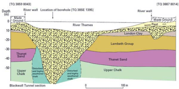
Some of these anomalies have been found to be more than 90m in depth and have relatively small surface areas. This is potentially a problem because if you insert a large load bearing column designed to use skin friction from the London clay, Lambeth group or Thanet sand, and it actually sits within a deep column of terraced gravel, the performance of the pile could reduce significantly. An Engineer in the audience stated that if you double the Pour Water Pressure the bearing capacity of the pile roughly halves. Clearly permeability in the terraced gravel is considerably greater than the clay.
This issue is even more of a problem because you could conceptually have a Pingo anomaly positioned between site bore holes. This means that you might be unaware of the issue on site until the point the pile is being installed. This is obviously too late in the day simply because by the point piles are being installed the design of the building and its foundations should have been finalised.
As I left the lecture it occurred to me this might make a decent thesis topic for a phase 2 student currently struggling for ideas. It looks like the Geologist lot are working hard to collect data on this issue. Combining this data with a detailed look at the risks a Pingo presents from a civil engineering perspective might prove interesting.
Laurie’s added site product from Phase 2
BP – Hydraulic fracturing hanger
Blog summary
I’ve been at BP for around 7 weeks working in the Projects & Modifications team. Unlike most other Phase 2 attachments, the BP one is slightly different. The overall ‘project’ doesn’t always exist as they are often carried out on a discrete basis, but, like all brownfield offshore engineering, it requires a lot of interface management with the core business of production, and other functional areas of the organisation (reliability and maintenance, wells, inspections etc).
I’ve recently taken up a project which involves the fabrication and installation of a hydraulic fracturing (frac) hanger to connect pipelines during a frac campaign of 4 wells. This is a purely structural project (even though I’m E&M!) but was given to me as it is being fast tracked through the project life cycle to meet an offshore construction date in July. The discrete nature of the project allows for sole ownership under direction from the asset programme manager. The scope is simple but allows exposure to the various stages of the project life cycle in a short time frame, while interfacing between various departments.
Background
The frac hanger is to be installed on to a laydown area of the platform which will allow for interface between the frac vessel and the platform. A 4” co-flexip pipeline is to be lifted in to position using the platform crane and connected into temporary flowlines located on the platform. This interface allows the vessel to pump large volumes of frac fluid down the well to initiate fracture. It will be used for the duration of the frac campaign and removed thereafter. There is not much requirement to chat through the design but I’ve added a picture of the proposed solution and an example of a ‘landed’ co-flexip style pipeline onto a frac hanger. The 3 pins are the interface between the hose and platform. An offshore survey is currently on going to confirm the exact scope of works required, but will probably include a destruct of a side panel and a construct of the frac hanger and new side panel. The hanger is designed to support the worst case scenario, 8.1MTe, of an emergency release of the pipeline from the boat end. Structural assessments have been carried out on the frac hanger and global structure of the platform. These are to be reviewed by a BP structural discipline engineer before approval for construction is granted.


Commercial
The well is co-owned and therefore when something, such as a frac campaign is scheduled, it must have agreement from all parties and will generally be co-funded accordingly. This is unless one party is willing to solely fund the operation to boost the production levels. In this instance, however, this is not what is happening. A third party contractor is funding the whole operation in return for a percentage of the production for a number of years. They are therefore carrying the risk of a non-increase in production (possible), while BP profit from the campaign if this isn’t so. That being said, the actual costs for engineering are fairly straightforward. The frac hanger is being constructed under the Engineering, Procurement and Construction contract that BP have in place with Wood Group (WG). WG will submit an estimate for all aspects required to get the frac hanger in place, BP will pay them while the third party contract will reimburse BP. Simple. I have no appreciation for costs in the construction industry but £250k for what is standard UBs and stock steelwork seems quite a lot.
General offshore construction observations
If you have got this far with reading, well done! I’ll finish off with some general offshore construction observations.
- Offshore construction scheduling is driven by the number of persons on board (POB) on the platform. There is a requirement for a number of ‘core crew’ to continue with production at all times. There is then a float above this for any others that may be working on the platform, with a self-imposed maximum POB (less than the beds available). This is then further constrained by flight frequency to the platform. In order to secure POB the requests must go through levels of authorisation at 12, 6 & 2 week gates, with the risk being accepted by the ‘gatekeeper’. Sort of like Gandalf on the bridge of Khazad-dûm. The ‘bums on seats’ on the flights must be confirmed at the 2 week gate. Below is an example of a platform POB level. In short, everyone requires POB and it is the asset planner’s responsibility to ensure that the correct POB are on the asset at the right time. This often means projects being delayed until areas of lower POB.


- The BP contract with WG is well established and works well. Value for money, probably not, but I’m not sure anything in oil and gas is. When WG are given a SoR they will engineer, procure and construct everything that is required. They have project and asset programme managers who are responsible for the delivery of the project with embedded construction supervisors on the platforms. Most of the onshore positions are also replicated on the BP side too! There appears to therefore be an element of ‘man-marking’ when it comes to the delivery of a project, however, the BP side is acting more as performance managers than project managers. That doesn’t mean you can sack all BP project managers, where they become invaluable is the integration with other functions within the organisation. This is key when ensuring that the project is actually delivered as they are rarely conducted without the help of the platform’s core crew. This is particularly difficult to understand when new to the business as decision rights aren’t always that straight forward.
I’ll look to blog when anything exciting happens, but in the mean time I’ll just explain other works areas I find myself part of.
- Construction of 4 lots of new choke valve pipework. I haven’t actually received the scope yet so nothing more is known than that!
- The appraise/select for the increase of 2 x electric heater capacities to allow 3 gas turbines to be run simultaneously on the platform. This involves selecting the best option based on estimates conducted by Costain and the technical knowledge of the various process, electrical, mechanical etc. engineers.
Your thoughts on blast vibrations.
I know I said I wouldn’t blog again but this is pretty interesting. I am looking at bidding for a contract for an 8 level basement in argillite rock in the centre of Brisbane. This will be the deepest basement ever built in Brisbane is quite ambitious.
I have two problems:
- The site is surrounded by heritage structures and the Riverside Expressway which have vibration limits of 5 mm/s.

Aerial View of Queens Wharf Development
 The shiny structure is Queen’s Wharf – you can see why blasting rock may be an issue.
2. I did an excavatability assessment and nearly the whole thing needs blasting.
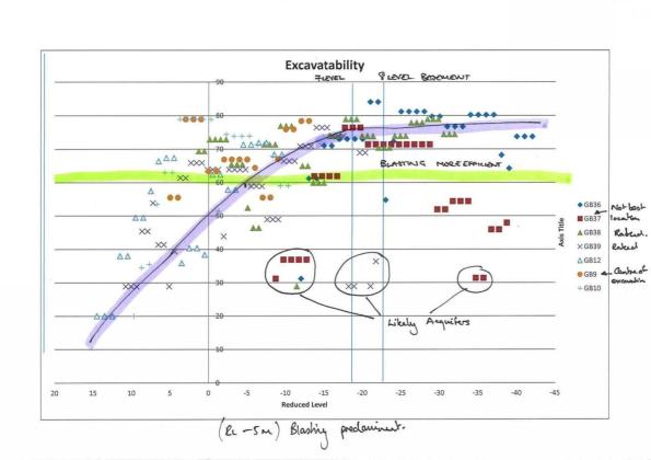
Excavatability Assessement (GSI vertical axis and Reduced Level horizontal axis)

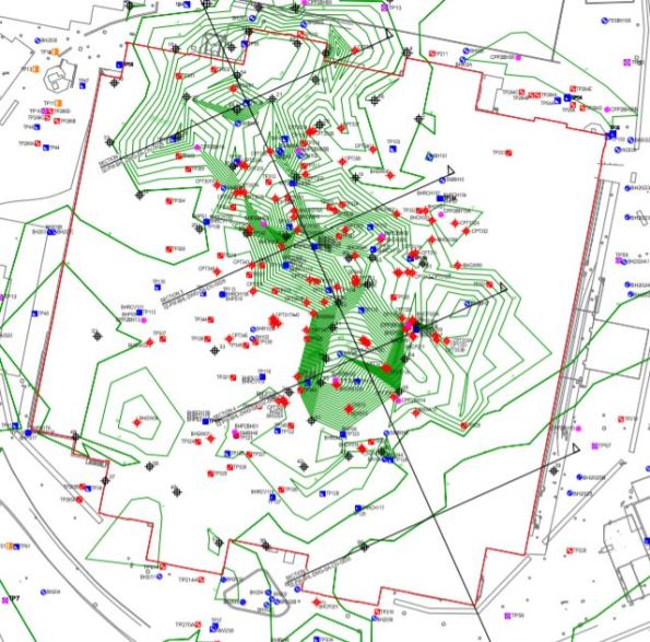
Site map and boreholes GB27-GB35 are missing!
The less permissable vibration the greater the cost (see below). The arguments for the 5mm/s limit come from a german code (the most stringent). I need to produce a paper to argue with ARUP that this vibration limit can be increased. There is about $3 M AUD in savings if I can increase or mitigate the vibrations. Any thoughts?

Some useful background reading.
200281_ Selection of Blasting Limits for Quarries and Civil and Construction
Rules of Supervision
During Phase 1 we learned of two rules of supervision (Civs; you may or may not have been party to this information, if not, it’s your lucky day).
I forget the order, but they are:
- “It doesn’t matter what you say, people will do whatever the f**k they want.” Phil Moffitt, 2016
- “Good to trust, better to check.” Fisho Fisher, 2016
Recently I was reminded of these valuable lessons.
Me: “Lads, I’ve got some tarpaulins for the dampers, can you take them up and see if you can fit them please? The eastbound damper will probably need tying down? Do you have any rope?”
Nacho the Labourer: “Yes, I think we have rope.”
Me: “OK good, do you have enough? Let me know if you need more and I’ll find some”.

Later I asked Nacho if he had completed the task. He said “Yes. And I am confident I got the right place”. Can’t argue.
A Yorkshireman in Sydney…
I will start with a confession: Not one for Facebook, Twitter, Instagram, or any other real interaction with Social Media, this is pretty much the first ‘proper’ blog of my life. (Although I suspect most are not interested in that fact and want to read on!)
Down-to-business, and following on from a string of “I do this on site” type blogs, I invite fellow bloggers, backseat readers and academic staff alike to read my submission.
Following in the footsteps’ of James Grant, I have found myself (not literally) employed as a Services Engineer on a hospital redevelopment project nearing its end. The Project is summarised as:
PROJECT
St George Hospital Redevelopment. (Stage 2 of 5.)

CLIENT
New South Wales Government, represented by Health Infrastructure.
MAIN CONTRACTOR
Multiplex, part of Brookfield Asset Management (Portfolio worth $260bn).
LOCATION
16 km directly south of Sydney’s Central Business District. (Think Opera House and the Harbour Bridge area of Sydney.)

DELIVERABLES
An 8-floor Acute Services Building; an extended car park (from 7 to 8 levels); an MRI unit; and, the refurbishment of the hospital’s existing Tower Ward Block.
PROJECT VALUE
$170m, of which $80m is assigned for Services.
CONTRACT TYPE
Known as a “GC 21”. Works are conducted under a Design & Build arrangement and the contract is comparable to that of the NEC 3.
CONTRACT RISK
A “fit-for-purpose” clause leaves much open for debate between Stakeholders. Despite User Group Workshops, differing perceptions of what this clause entails leads to time-consuming meetings and potentially costly outcomes.
RESPONSIBILITIES
According to the Project Management Plan’s description of my role, I am responsible for the management of all aspects of electrical, mechanical, hydraulic, fire, security and lift services design, coordination, and installation, completion, commissioning and training for the project. This includes quality control, negotiation with subcontractors and obtaining approval as well as liaison with the Client, Architect, Consultant, Subcontractors, Construction Team and the User.
REALITY CHECK
Although my job description is quite clear, the initial reality of my responsibility has been different. Understandably stuck somewhere between a Graduate Engineer and Site Engineer in the minds’ of others, I have had to reinforce why I am on site, what I am trying to achieve, and how I should achieve it. Effective communication is proving critical; time is at a premium from those that I am seeking help from.
Beyond the observations listed above, I am intrigued at just how complex applying Design Philosophy in Construction can be. Focusing on St George Hospital as an example, from its inception of an 8-bed ward cottage hospital, constructed in 1894, it now has approximately 550 beds, 2500 staff, serving 250,000 district residents. More than 45,000 admissions and 723,000 outpatients are administered each year. The last iteration to the hospital’s expansion, a previous redevelopment project, was conducted in 1980 costing Aus. $200,000,000, designed to last 50 years. The problem is the fundamentally the same – population modelling. To compound matters, construction constraints on the site are increasing – building more on a live hospital site, with less space, more traffic and, increasing competitiveness for resources. The space available to off-load resources for the entire site is constrained to 825m², approximately 1/7th of a football pitch.
Future proofing designs is a difficult art. In my opinion, it is the resilience to change. To achieve this, one must look beyond life-cycle costing and focus more on whole-life value; a philosophy difficult to sell in business cases which focus on value-for-money for a specific budget year.
Away from trying to understand more about Construction, and despite bags of encouragement from my new work colleagues, who have rather ingeniously given me an Australia nickname – Fisho – I still drink Yorkshire Tea, not oodles of coffee. (Although, if I had my time again, I would open a coffee shop in Sydney. #moneyprinting)
Until next time,
Fisho
Safety Concern Over Temporary Works
As Project Engineer I have been overseeing the pile installation, pile breakback and enabling works prior to the FRP (form, reo, pour) contract on the two abutments and central pier for the Canal Bridge, sharing the work load with my partner from the Royal Australian Engineers (RAE).
Abutment A is situated between a high pressure gas main & sewer to its east, and 6 lane carriageway to its west, excavation has therefore been relatively complex to say the least.
After taking an academic day, I returned to site to quality assure the on going excavation. A temporary works designer had supplied details on the installation of a UC shoring system to support the gas main while excavation took place for Abutment A (the gas main is marked by white vertical conduits in the photo). Emanon (sheet driving subcontractor) had driven UC’s into the ground, ready for sleepers to be inserted between them as the excavation progressed. While away though the Site Foreman and Site Superintendent had decided the shoring needed to be extended (see photo below).
 Figure 1 – Abutment A Excavation, Canal Bridge
Rather than reactivating Emanon to install further UC’s, they used a discarded railway line and used an excavator to drive it into the ground. There were a number of issues with this;
- The railway line did not have the same local geometry as the UC’s;
- The correct toe depth was not achieved;
- Previous impact or damage to the railway line was not known;
- A verification of the revised temporary design was not signed off;
- A Senior Project Engineer had not signed off on the approved installation method of the temporary works.
I therefore closed the excavation and had it backfilled until the design could be approved or verification rectified the design. This was to the annoyance of the foreman and superintendent with the usual retort of, “but we’ve always done it this way”.
I took measurements of the local geometry of the railway line and instructed our temporary works designer to calculate the suitability. The soil properties were extracted from the GI and assumptions had to be made on the yield strength of the railway line (200 MPa). Brom’s method for laterally loaded piles was used and considered both short and long pile failure modes. A FOS of 2 was implemented in the verification. The design was then verified by a second temporary works designer, once complete the excavation could be reopened.
If you were wondering, the state of the reo cage in the pile in the foreground has had an NCR raised against it as the piling subcontractor forced it into the CFA pile using an excavator bucket rather than vibrating it into place.
How much reinforcement is too much reinforcement?
I draw your attention to the photos below as an illustration of the problem. It shows the quantity of steel being installed both longitudinal and transverse.

Photo 1 – B40 Longitudinal Bar (The steel coming towards the photo is the bottom longitudinal steel at the end of a beam)

Photo 2 – Transverse Reinforcement

These beams are at the B01 level in the Battersea Station Box, in places 3.8m deep, acting as transfer beams for the over site development. They have been designed for point loads of up to 10MN, transferring the load to plunge columns.
If I now break this into two:
Longitudinal steel – The quantity of longitudinal steel in places is greater than the 0.04Ac. I thought this 4% figure existed to prevent brittle failure and allowed tension cracks to appear in the concrete prior to the beam failing. Therefore, if this is the case then what are the implications of a design such as this?
Transverse steel – Looking in the guidance for the minimum spacing of transverse steel, the distance should be 20mm (10mm aggregate) to form a bond between bars. Clearly this does not, therefore I see three problems potentially arising. Firstly a proper bond will not be able to form between traverse bars; does anyone know what implication this will cause? Does it mean a reduction in shear resistance? Secondly it does not allow for vibrating pokers to be lowered into the concrete at this location during casting and thirdly it acts as a sieve during pouring, causing separation in the concrete. All of which are mentioned in the codes when designing transverse steel.
Looking into the detailing a bit further I discovered in the IStrutE detailing guide, the table below shows the difference between size and diameter of bars. Apparently one should not confuse size with diameter, after all a size 40mm bar is 46mm in diameter. Therefore when this transverse steel was detailed, if the size was assumed to be the diameter, all those millimetres add up to the situation in the photos above.

Service clash and visualising drawings.
The East Office at Hinkley Point is a 13,000sqm building formed of 12m x 3.6m x 3m modules. Currently undergoing first fix services it is the furthest along of three similar structures on site – it is not yet water tight but that is a different issue.
This post is just to quickly share the issues that have been experienced on my area of the site regarding service clashes, particularly drainage.
A 3D model was constructed for the building – clash detection was said to be acceptable. Foundations were constructed by another contractor on a contract with the Principal Contractor. The modular building contractor approved the as built strip founds by survey prior to beginning install of the modules stating that the greatest disparity in the service pop ups was +/- 40mm.
The intent was for vertical soil stacks to connect directly into the waste pipes from WCs in the corners of each unit. This did not account for the steel plate in the corner of every unit to allow attachment of plasterboard or for certain units to have their beams sit directly on top of the service pop ups. I advised (as PC we can’t do anything else) that they cut holes in the plate, as they were going to install a series of flume like bends which would mean additional boxing in. It also meant the plumbing sub contractor taking on risk from straying from the design which was unfair on his part.
Also, I think John mentioned always to check cross-sections rather than just look at plans. I have seen this first hand as a kitchen extraction duct is being installed that allows only 2.2m headroom, not including a floating ceiling to be installed. The spin off from this is that if this duct is not changed it creates a ceiling void above 800mm depth, thereby requiring fire detection or sprinklers. The duct also (as everyone who has seen it agrees) looks odd. Which has been enough to get the designers down to have a look this week. The duct is extraction for a reheat kitchen, yet it is twice the size of the same piece of kit for a proper kitchen in an adjacent building. Maybe a spec issue or stray decimal point.
The M&E, although not what I wanted to be involved in, has been an education in project life cycle and the importance of understanding what drainage goes where prior to casting concrete, signing off surveys, properly visualising the end result of an asset or committing to a design in the case of the extraction ductwork. With time pressure it is not as easy to be as thorough in some areas viewed as less critical but it is often the details that cause bigger problems from what I have seen over the past 7 weeks.
Hoping to get mud on my boots soon or at least within touching distance of a bit of plant (within the safe zone, having filled out the requisite forms etc).
Thoughts on over excavation of a contiguous pile retaining wall…
I’m currently looking at the implications of over excavation on the basement (passive) side of a contiguous piled retaining wall. Whilst onsite I became aware that the sub-contractor responsible for the basement reduced dig had moved beyond a hold point before another sub contractor had completed the temporary reduced level on the retained (active) side. The reasons for this are numerous but boil down to poor communication and management of the required design construction sequence. Figure 1 below is a sketch of the wall cross section during final construction and temporary cantilever states in accordance with the design checks conducted.
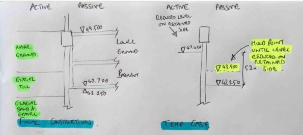
Figure 1 – Final construction and temporary construction stages
In order to understand the impact of this error I wanted to analyse the impact of the worst case (figure 2) where the full passive excavation had been completed and no excavation had occurred on the active side. Note that fortunately work was stopped on site prior to this case occurring!

Figure 2 – Worst case if construction sequence followed incorrectly
The initial WALLUP retaining wall analysis (step 1) gave a minimum pile length for stability of 12m from pile platform level (PPL) to the toe at 39.1mOD. Re-analysis for the worst case shown above caused an increase in the max BM, shear and displacement of the wall in SLS conditions and a failure in ULS conditions due to passive failure. This would be a simple conclusion if the wall had been constructed to the 12m length from the original retaining wall design. However, the contiguous wall is also required to support an axial load for the planned structure above. The initial analysis of axial capacity (step 2) lead to a minimum pile depth for axial compression of 28.5mOD and a pile length of 20.6m from PPL. This design was based on resistance provided in skin friction below formation level and a minimum rock socket of 1.5m. Note however that the initial structural reinforcement design (step 3) only extends to the depth calculated for stability (in step 1) and was based on the maximum moments and shear from this calculation. The image below summarises the initial pile design results.
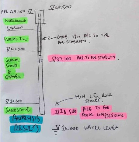
Figure 3 – Initial design analysis results
So, drawing conclusions now on the effect of the over excavation shown in figure 2 becomes slightly more difficult. My initial thoughts are:
1. The passive failure issue is now removed due to the increase in pile depth.
2. There is still an increase in BM and shear force that would mean the structural reinforcement would be under designed and could lead to an STR failure.
3. The structural reinforcement should extend down to the new pile toe depth for stability.
4. There would be an increase in deflection of the wall which could lead to other issues including eccentric loading in the final permanent state.
I’d welcome any comments or thoughts on the above logic or any conclusions I may have missed.
Any Site Managers on Phase 2?
For anyone that thinks they sound like a dick when they tell someone to move something that’s not stored in the right place:
http://www.bbc.co.uk/news/uk-england-london-39816357
