SLOPE STABILITY ASSESSMENT FOR TOWER CRANE ERECTION
Apologies for the long winded explanation that follows this intro! In summary, I have a slope stability problem and if anybody could provide solutions in addition to the ones I’ve suggested below that would be great. My solution also requires fill that I assume would need to be compacted? Has anyone done any work on compacted effort required in coarse grain soils? Any other thoughts appreciated also.
My primary responsibility at the moment is managing the construction of the tower crane for the SEB site. This has principally involved managing and coordinating contractors to ensure that all enabling activity is completed for this Saturday (1 July 17).
The tower crane will be constructed in sections through the use of another 300 tonne mobile crane. Figure 1 below shows the site layout for the tower crane construction. The main boom arm will be constructed on the road before being lifted into position. The red highlighted area shows the extents of a slope which separates the two construction zones (North and South) and the blue highlights the outrigger pad areas.

Figure 1 – Site layout for tower crane construction.
The crane company are required to complete a lift study for the exact location of the crane in order to accurately calculate their maximum boom radius and resulting loads that will be transferred into the ground via the outriggers. During planning the location as shown in figure 1 was agreed and a lift study was completed by the crane subcontractor. The resulting loads were 90 tonnes through each outrigger, which with pads of 2.5 x 2.5 m creates an operating stress of 144Kpa (I conducted a quick bearing capacity check for the loose sand layer to 2.5m which produced a stress at which failure occurs of 360kpa. No FOS!). One of our contract clauses requires MPX to complete DCP testing for any activity requiring outriggers. It was only once the positions of the outriggers were placed on the ground that I realised that we could have a possible slope stability issue. The image below shows the profile of the slope and the position of the mobile crane outriggers.
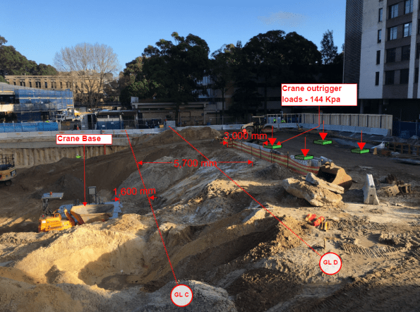
Figure 2 – Current slope profile and position of 300T Mobile crane
The proximity of the outrigger pads to the crest of the slope was a concern. The geotechnical engineer had also specified batters of 2:1 (H:V) throughout. The slope was clearly not 2H:1V. It was almost 1:1 with reduced level (RL) at the top of crane base of 24.000m AHD and a RL of 29.000m AHD at the top of the slope.
Transferring risk is the Multiplex way and the decision was made to get the Geo consultant (Coffey) to inspect and approve a solution. They will be visiting site tomorrow!
Smelling an opportunity to conduct some much-loved geo analysis, I immediately leapt into action and retrieved my John Moran Slope Stability notes in order to see if the current slope would be safe. About an hour or so later I realised that I was stumped. I understood the Bishop’s method of slices, but I couldn’t see how to model the surcharge load created by the crane outriggers (any advice would be appreciated).
I eventually decided to go back to first principles and use the equilibrium equation ∑M = 0. The idea was to take moments (resisting moments divided by disturbing moments) about the origin of the slope to determine a factor of safety (FOS).
Assumptions:
- No GEO reduction in soil parameters. All ϕ’ values etc taken from Coffey’s GDR.
- GWL is at measured mean levels (22.6m AHD) and therefore no pore pressures considered in calculations.
- Failure would be a circular slope within the loose sand layer (this was also based on the fact that the pile cap would provide toe stability and additional anti-clockwise moments about the origin).
- No consideration made in hand calculations for DC1 or DC2 i.e. factoring the soil parameters of loads.
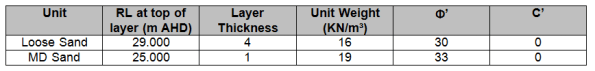
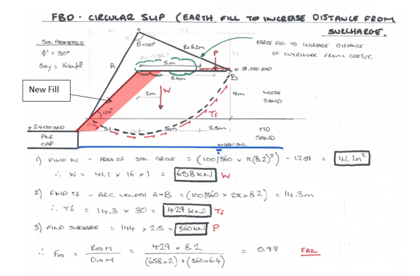
Figure 3 below shows my hand calculations for the existing site conditions. The FOS was 0.91; so a risk that the slope would fail if not modified.
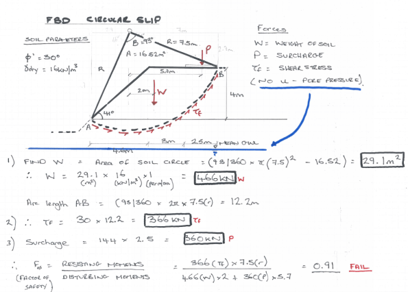
Figure 3 – Slope stability hand calculations for current soil profile.
When looking at solutions to this problem I could see 2 possible solutions:
- Place additional fill on the slope to increase the distance of the surcharge from the crest to 5 metres.
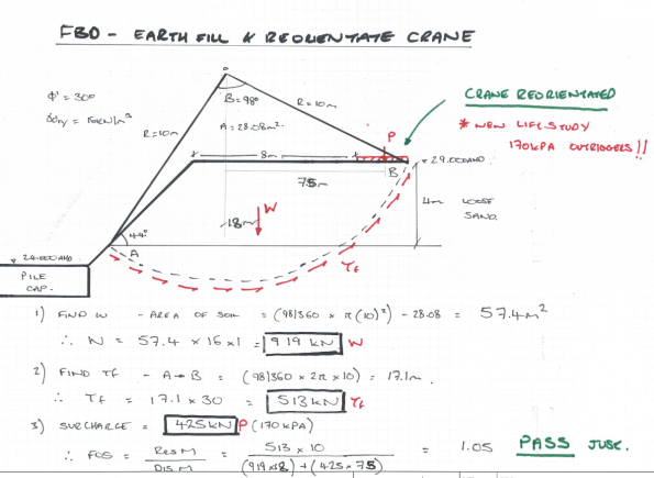
- As above, but also re-orientating the crane to further increase the distance of surcharge to the crest (This required a new crane lift study as boom ranges would increase; this was completed for contingency and outrigger stresses increased from 144Kpa to a maximum of 170Kpa).
Figure 4 – Potential solutions on a mark-up.
Solution 1 Calculations – Build up slope with fill only (FAIL).
Solution 2 Calculations – Build up slope with fill and re-orientate the crane (PASS –JUST).
My results showed that the crane would need to be re-orientated and additional fill would need to be placed to increase the distance between the surcharge load and the crest of the slope. Mindful of the fact that my hand calculations may not be entirely accurate, I also checked on GEO5. Results are shown below, generating similar results for the current profile but passing on both solutions (only just passing for solution 2).

Based on these calculations I would suggest that the distance from the crest of the slope to the outriggers needs to be increased by placing some additional fill and by re-orientating the crane. The lifting will also need to be monitored very closely to ensure that loading conditions don’t increase (i.e. lifting study boom ranges are not exceeded) and the outrigger plates are the correct sizes. It will be interesting to see what the Geotechnical engineer comes up with tomorrow.

Good stuff for a TMR
I think there are a couple of problems in 1
1 The outrigger base could be assessed as a foundation on a slope: If the foundation shear fan are not intercepted by the slope , then the slope doesn’t affect the bearing capacity. Taking the forward outrigger plate B=2.5m The shear fan for a base failure will extend apprx 2 B from the edge( 5m) So if the slope commences before this the bc will be reduced. IF it is not, for phi’ = 30 qc= 0.5 B Ny gamma’
qult=1.25 x 20 (dry) x 18 (Ny) = 450kPa .v your 144kPa
2 The two weights causing slope instability are the weight of the slope and the outrigger weight. So steepening the slope ( while it does increase the effective stress on the slip surface, it causes the slip – So if the bc is not compromised from 1 then steepening the slope wouldn’t be a good idea
Some other stuff. I like the attempt at the hand calc limiting equilibrium assessment BUT it looks like the slip surfaces are always roughly a quarter of a perimeter at a radius of 9m or so , so will be 24m or so.
The shear resistance on the surface is mis-calculated. It is the area of the slip surface (so 24x 1m2) This is multiplied be the effective stress on the surface (it is because this varies around he surface that slope stability calcs are a pain) multiplied by the tan of phi’. IF the average effective stress is (say 3x 20= 60kPa) 60xtan 30 = 37kPa and the restoring moment is 37xarea x lever arm. So 37 x 24 x 9 say 7000kNm ( you have around 5000kNm)
So sensitivity
As the slope steepens FoS will reduce
As the base gets closer to the slope edge the FoS will reduce
I would raise the GWL to dredge level
I think the phi’ is low – perhaps but OK for a loose SAND
BTW I have a thesis title in this area provided by an ex colleague of yours who now manages his family firm
I can’t offer any numerical advice on tjis one i’m afraid.
Interesting that there doesn’t seem to be enough space for a 2:1 slope from your diagram and still allow you to fit a crane, so why did the Geotechnical Engineer specify that I wonder?
With a similar issue on site we managed to swap for a bigger crane with a longer jib to avoid overloading a jetty (a revised lift plan doesn’t take long despite all the APs whinging). Not an option for you i guess with a tight space at the top of the slope.
Can you let us know what the specialist ‘fall guy’ has to say after their site visit.
Al, we are using quite a bit of reinforced earth here for tower cranes. Not something I’m directly involved in but it’s tensar and I’d imagine figures readily available for its performance. I can maybe dig out some info if you want. It’s just L-shaped steel mesh slope forms onto which material we grade on site is compacted.
Might not be of much use to you now but could increase the shear strength of your loose sand and give you another comparison.
Al, Would another option be to distribute the load P over a greater area, ie a 3x3m mat would reduce the stress to 100kPa. However it would also distribute the load nearer the slip surface, so might not be as beneficial as required. But constructing a piling mat or concrete (potentially with mesh) platform would distributing the load over a larger area reducing the stress. If it distributed more longitudinally along the top of the slope it could then be modelled as a line load.
Thanks for all the comments.
Jon – First point coffey raised was that a minimum of 5m from outrigger to crest of slope must be maintained; for the reasons you describe in problem 1. Coffey also completed a allowable bearing pressure calculation : qf = 0.5 x 2.5 x 16 (dry) x 18 (Ny) = 360 Kpa, which they then divided by 2 , so q allowable = 180 Kpa vs 144 Kpa. In terms on the slope angle, their engineer used a sighting clinometer to check the slope angle and he was satisfied. The shear resistance calculation makes sense, although you used 20 Kn/m3 for the dry density, if I use 16 kn/m3 as per the ground model it reduces the shear resistance! (3 x 16 x tan(30) = 27 Kpa x area x lever arm = 3250 Knm vs 3517 from original calc)
Any info on this would be appreciated for potential TMR. Could you email that thesis to me? allanbartlett@yahoo.co.uk. Thanks
Tony – Turns out that the RL at top of slope is 2m higher than in the geotec’s original design! Not entirely sure why/how this happened, but it was never picked up despite the fact that the bulk excavation dwg clearly shows the RLs.
Dan – Good point and I should’ve mentioned; a piling mattress sits on top of the loose sand (600mm deep) with a geo-grid beneath it. This was placed to increase the shear strength of the soil for the CFA rig during retention piling. So the bearing capacity should be higher than estimated above. Not sure how much this would assist in reducing slope failure as it doesn’t increase the eff stress along the shear failure plane.
Henry – The idea of a line load by using a longer outrigger pad, say 2.5m x 5m to reduce to stress is interesting. I found a slide in Jon’s notes that indicates a change in the vertical stress distribution for strip footings (4-5B, instead of 2-2.5B for a square footing). So if a line load was modeled It may cause the shear fan to intercept the slope again?
Can’t seem to get pictures in the comments, but this is extract from Geo tech’s report:
‘Edge of the crest is 3m away from edge of crane pads. It is advised to backfill in order to increase the clearance to 5m. We recommend compacting/rolling the surface on top of the slope. The slope is satisfactory and is measured at approximately 42 degrees ‘
We are now backfilling and compacting with the excavator bucket (This seemed a bit crude to me but not sure of any other way). We have also decided to re-orientate the crane so we should have a safe distance of 7-8m. We have also instructed the Geotech engineer to attend site to re-inspect once remedial works have been completed.
Interesting comments about transferring risk and the assumption/inferrance that all the risk is transferred to the Geo consultant. What do you think would be the outcome if something did go wrong?
Safety/cost/delays/reputation/etc. would all hit the project and main contractor hard. How much of the flack do you think would actually be passed to the consultant that he/she could not blame on site control issues?
I have no direct experience of such a situation but I suspect that the main contractor would suffer just as much as, if not more than, the consultant. I am pretty sure the consultant will build in some pretty hefty FOS to any calculations anyway!